1. OVERVIEW ......................................................................................................................................1
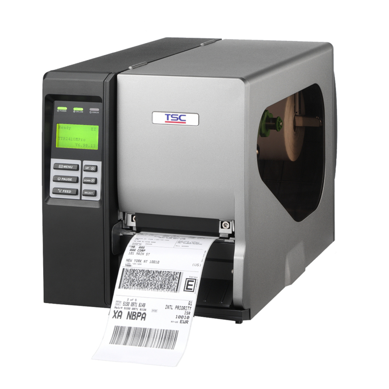
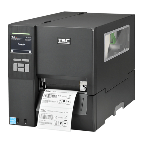
1.1 Front View...................................................................................................... 1
1.2 Rear View....................................................................................................... 1
1.3. Specification................................................................................................. 2
1.3.1. Printer ............................................................................................................ 2
1.3.2. LED............................................................................................................... 3
1.3.3. Button Operation............................................................................................ 3
1.4. Supply Specification.................................................................................... 7
1.4.1. Paper.............................................................................................................. 7
2. ELECTRONICS................................................................................................................................8
2.1. Circuit Description....................................................................................... 8
2.2. MCU Circuit and MCU PIN Description..................................................... 10
2.2.1. MCU PIN Description:..................................................................................11
2.3. Reset Circuit............................................................................................... 16
2.4. Memory Circuit........................................................................................... 17
2.5. Decoder Circuit .......................................................................................... 18
2.6. Memory Map ............................................................................................... 19
2.7. Print Head Circuit....................................................................................... 21
2.8. Stepping Motor Drive / Protection Circuit................................................ 22
2.9. Power Circuit.............................................................................................. 24
2.10. Parallel Interface Circuit .......................................................................... 25
2.11. Serial Interface Circuit ............................................................................. 27
2.12. USB Circuit ............................................................................................... 28
2.12.1. USB PIN Function ......................................................................................29
2.13. Sensor Circuit........................................................................................... 31
2.13.1. Gap and Black Mark Sensor ........................................................................31
2.13.2. Head Open Micro Switch ............................................................................32
2.13.3. Peel-off Sensor............................................................................................33
2.14. Cutter Drive / Protection Circuit.............................................................. 34
2.15 Summary of PCB connectors................................................................... 35
3. REPLACE and INSTALL IMPORTANT PARTS..............................................................................38
3.1. Replacing Top Cover.................................................................................. 38
3.2. Replacing Lower Cover and main PCB .................................................... 39
3.3. Replacing Platen Assembly....................................................................... 41
3.4. Replacing the Stepping Motor Assembly and Stepping Motor .............. 42
3.5. Replacing Label Guide Adjustment Knob Assembly .............................. 44
3.6. Replacing Gap/Black Mark Sensor Assembly ......................................... 46
3.7. Replacing Print Head Module Assembly.................................................. 47
