IECHO TK4S User manual

1

2
Dear Customer:
FOREWORD
TK4S series high precision digital cutting system can automatically complete the cutting, kiss cutting, carving, drilling,
creasing, marking and so on. With automatic feeding and collecting system, jobs can be done quickly, which is also
suitable for advertising signs, printing and packaging, automotive interior, furniture sofa, composite materials and other
industrial production. It is the almighty champion of material cutting. Thank you for choosing IECHO high speed digital
cutting system.
Here is our sincere hope and forever target for this production specification can be easily and comprehensively to be
understood by you. In order to use this equipment properly, please read this user manual carefully and follow each step
after reading. From the beginning to the end, IECHO “star service” will be accompanied by you, no matter what problem
when you encounter, please check out the telephone number and address below and contact us. Here is our great honor and
responsibility to serve you with any inquiries. Thank you again for choosing IECHO products, if there is any change for
the manual contents due to product improvement, we apologize in advance that we won’t make another notice.

4
Directory
1. Equipment Overview.......................................................................................................................................................................1
1.1 Features..................................................................................................................................................................................1
1.2 Composition.......................................................................................................................................................................... 1
1.3 Working Principles................................................................................................................................................................1
1.4 Technical Parameters............................................................................................................................................................ 2
1.5 Cutting Head.........................................................................................................................................................................3
1.6 TK4S Cutting Tools............................................................................................................................................................. 4
1.7 TK4S Direction Information................................................................................................................................................ 7
1.8 List of Tools......................................................................................................................................................................... 8
2. Preparation.....................................................................................................................................................................................10
2.1 Installation Location............................................................................................................................................................10
2.2 Personnel............................................................................................................................................................................. 10
2.3 Power Requirement............................................................................................................................................................. 10
2.4 Environmental Conditions.................................................................................................................................................. 11
2.5 Basic Device Compressed Air............................................................................................................................................ 11
2.6 Flooring Space Requirement...............................................................................................................................................11
2.7 Operation Space Requirement.............................................................................................................................................11
3. Installation..................................................................................................................................................................................... 12
3.1 Opening and Inspecting Packing Crates............................................................................................................................. 12
3.2 Setting Up the Base Frame Structure..................................................................................................................................13
3.3 Assemble the Cutting Beam................................................................................................................................................16
3.4 Installing the Vacuum Plates.............................................................................................................................................17
3.5 Leveling the Table Plate....................................................................................................................................................19
3.6 Advertising Industry: Installing the Regional Air Valves and PVC Pipes Images........................................................... 22
3.7 Assemble the X Axis Side Covers.................................................................................................................................... 26
3.8 Pneumatic Control.............................................................................................................................................................28
3.9 Connecting the Electric Box............................................................................................................................................. 30
3.10 Assemble main cable etc.................................................................................................................................................31
3.11 Install the Conveyor Belt Guide Rollers Device............................................................................................................ 32
3.12 Install the AKI Device.....................................................................................................................................................35
3.13 Other Cables Function of Instructions............................................................................................................................ 36
3.14 Assemble the Workstation.............................................................................................................................................. 38
3.15 Install the Conveyor Belt................................................................................................................................................ 40
3.16 Tension the Conveyor Belt..............................................................................................................................................42
3.17 Assemble the Milling Support Device............................................................................................................................43
3.18 Install the Covers of The Front and Rear Side................................................................................................................48
3.19 Circuit Boards....................................................................................................................................................................49
4. Danger Areas During Initialization...............................................................................................................................................50
4.1 Danger Area On the Module Carriage.............................................................................................................................. 50
4.2 Safety Device On the Machine and PC Table.................................................................................................................. 51
5. Cutting Head Installation...............................................................................................................................................................52
6. Tool Installation.............................................................................................................................................................................54
7. Operation....................................................................................................................................................................................... 60
7.1 Preparation...........................................................................................................................................................................60
7.2 Steps.................................................................................................................................................................................... 60
8. Maintenance.................................................................................................................................................................................. 61

5
8.1 Daily Maintenance.............................................................................................................................................................. 61
8.2 Weekly Maintenance...........................................................................................................................................................63
8.3 Monthly Maintenance......................................................................................................................................................... 64
8.4 Quarterly Maintenance........................................................................................................................................................64
8.5 Annually Maintenance........................................................................................................................................................ 64
9.Common Error and Troubleshooting............................................................................................................................................ 65
10. Safety Attentions......................................................................................................................................................................... 66
11.Other Information........................................................................................................................................................................66
11.1 Products Details.................................................................................................................................................................66
11.2 Warranty Card................................................................................................................................................................... 66
11.3 Product Maintenance Details............................................................................................................................................ 67
11.4 Statement........................................................................................................................................................................... 67

1
1. Equipment Overview
IECHO Automatic Digital processing line can be used for full-time production, fulfilling the requirement of high
efficiency, by using the maximum capacity of the machine to complete the 24/7 production.
1.1 Features
Regional vacuum zone
Vortex vacuum control
Automatic sheet feeding
Conveyor system
Camera registration system
High-speed and high-precision cutting tools
Collection table for cutout elements picking
No manual operation needed
1.2 Composition
TK4S series digital cutting machine series is composed of Electrical box, Main body, Vacuum and Auxiliary devices.
Software includes file processing part and machine controlling part.
According to user’s demand, one or more tools can be used: Tangent Tool, Oscillating Tool, Kiss-Cut Tool, Router,
V-Cut Tool, Creasing Tool, Driven Rotary Tool, North & Drill Tool, Pen.
User can scan the bar code created by RIP software.
1.3 Working Principles
Import the files into SmartCut/iBrightCut, the user can process the files (editing and nesting) and send the processed
cutting files to CutterServer. According to the cutting files, the controlling system will create motion control signals. With
the signals, servo motors execute the tools lift/down and modules movement. Thereby, the machine achieves the high-
speed and high-precision cutting

2
1.4 Technical Parameters
Definition
Parameter
Model
TK4S 2521(TK4S 2521 is just one model, more dimension is available).
Cutting Area
2500*2100 mm (98.4 inch *82.6 inch)
Machine Dimension
3340*3000*1273 mm (131.4 inch *118.1 inch *50.1 inch)
Weight
1550 kg
Vacuum Zones
3 - 24
Max Speed
1500mm/s (59inch/s)
Accuracy
0.1mm
Max Cutting Thickness
50mm (1.96 inch)
Modules
Can be installed up to 3 cutting heads
File Formats
DXF、PLT、PDF、HPG、HPGL、TSK、BRG、XML、CUT、OXF、ISO、
AI、PS、EPS
Interface
Serial Port / USB Port
Adsorption
Vacuum Pump
Power
Single-phase 220V / 2KW (exclude the power of feeder)
Three-phase 220V/380V 5.5KW/7.5KW*n (n is the quantity of vacuum zone,
exclude the power of feeder)
Power Requirement
220V/50/60HZ、380V/50/60HZ (Three-phase five-wire system)
Air Pressure Requirement
0.6~0.85MPa,Dry compressed air
Operating Environment
Temperature:0℃-40℃;Humidity:20%-80%RH
Storage Temperature
- 20 to + 55
°C

3
1.5 Cutting Head
TK3S /TK4S
Universal
Cutting head
All tools can be installed
in(except 1KW router)
Cutting thickness: 50mm
1.8KW Router
Power:1.8K
W
60000rpm
water cooling
cleaning device
Cutting thickness:
2mm-6mm Di-bond
20mm Acrylic
1kw Germany
Router
Power: 1kw
60000rpm
Air cooling
cleaning device
Cutting thickness:
2mm-6mm Di-bond
20mm Acrylic
TK3S/TK4S -
Marking head
Two pens
3 times/s/pen
Material thickness:
50mm
TK3S/TK4S -
North & Drill
head
Two heads
3 times/s/head
Material thickness:
10mm
4
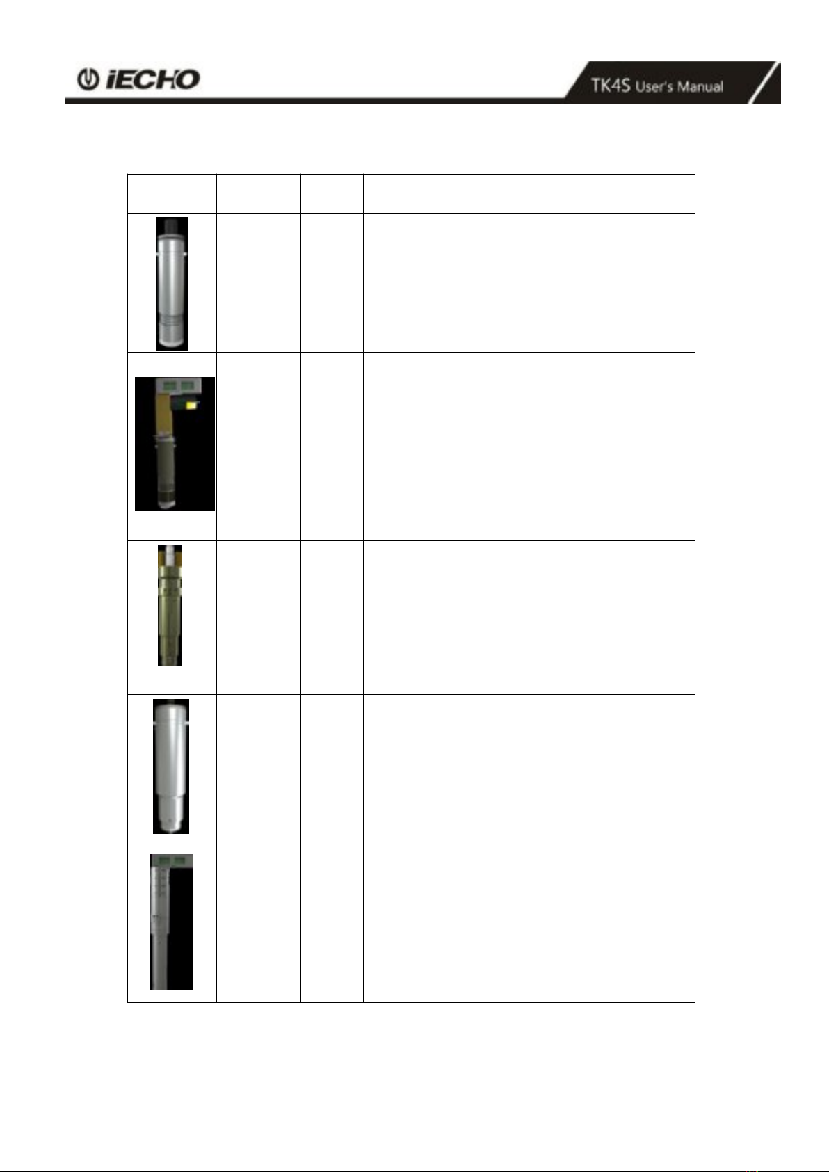
1.6 TK4S Cutting Tools
Illustration
Name
ab.
Feature
Materials
Tangent
Tool
CUT
Universal Cutting Tool
for materials up to
5mm thick.
Fast speed and low
cost.
Cardboard, Chevron
board, ABS board,
Gasket, Carbon fiber
prepreg, PVC tarpaulin,
PE, XPE, Label, etc.
Electric
Oscillating
Tool
EOT
High-frequency
electric-driven tool
with 80W power
options. Max cutting
speed
1m/s for soft and
medium-density
materials.
Chevron board,
Corrugated board, Gasket
board, Gray cardboard,
PE, XPE, EPE,
PU leather composite
sponge, Coil car mat, etc.
Pneumatic
Oscillating
Tool
POT
Powerful air-driven
tool with extended
stroke for dense
materials up to 50mm
thick.
Composites, Honeycomb
board, Asbestos gasket,
Graphite gasket, Sponge,
EPE, etc.
Kiss-Cut
Tool
KCT
Half-cut tool for vinyl
materials.
Vinyl, sticker, reflective
film, etc.
Driven
Rotary
Tool
DRT
Cutting tool with
driven rotary blade for
fabrics and technical
textiles with high
processing speed.
Fabrics, carbon fiber,
glass fiber, aramid,
carpet, etc.
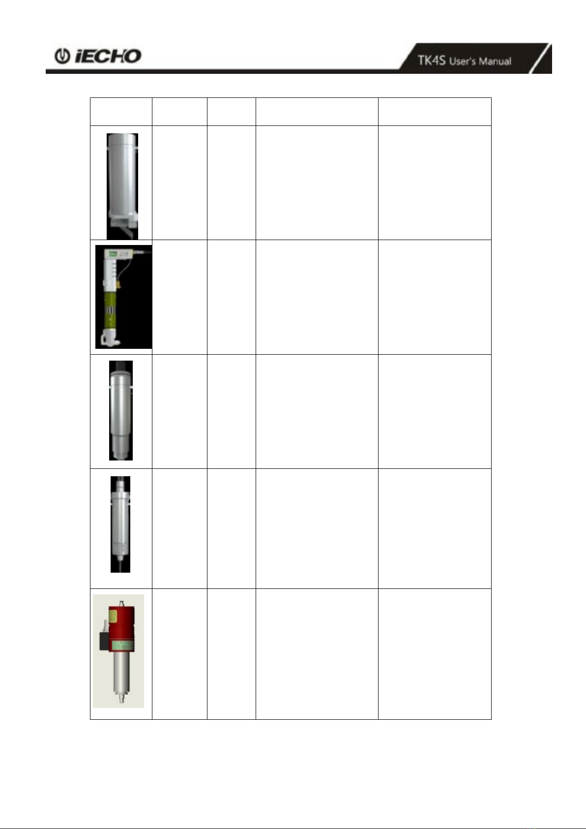
5
Illustration
Name
Ab
Feature
Material
V-Cut
Tool
V-CUT
Tool with 5 cutting angles
(0°,15°,22.5°, 30°,
45°). Create 3D
structural design.
Honeycomb board,
sandwich board, KT
board, Gray board, etc.
Powerful
Rotary
Tool
PRT
Powerful tool with
driven rotary blade.
textiles, carbon
fiber, glass fiber,
carpet, fur, etc.
Creasing
Tool
CTT
Creasing wheels for
carton box making
Corrugated board,
carton
board, etc.
CNC
Router
MILL
Routing tool with
high-performance
routing on hard and
tough materials up to
16mm thick.
Power: 350W;
RPM:60000rpm;
Max thickness:16mm.
Acrylic, Di-bond,
aluminum composite,
MDF, etc.
CNC
Router
MILL
1KW
Routing tool with
high-performance
routing on hard and
tough materials up to
20mm thick.
Power: 1KW;
RPM:60000rpm;
Max thickness:20mm.
Acrylic, Di-bond,
aluminum composite,
MDF, etc.
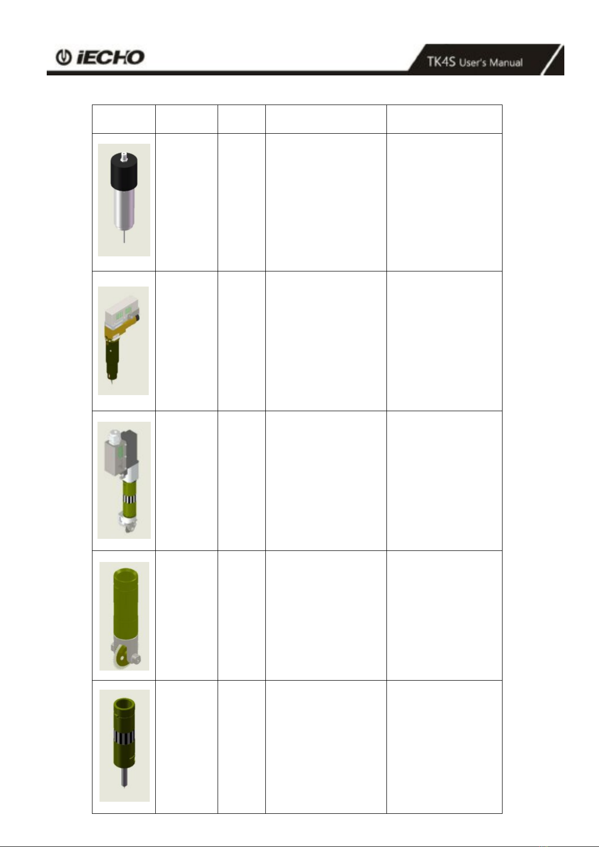
6
Illustration
Name
Ab
Feature
Material
CNC
Router
MILL
1.8KW
Routing tool with
high-performance
routing on hard and
tough materials up
to
20mm thick.
Power: 1.8KW;
RPM:60000rpm;
Max thickness:20mm.
Acrylic, Di-bond,
aluminum composite,
MDF, etc.
Electric
Oscillating
Tool
EOT3
High-frequency electric-
driven tool with
200W power options.
Max cutting speed
1m/s for soft and
medium-density
materials.
Chevron board,
Corrugated board,
Gasket, KT board,
Gray cardboard,
PE,XPE, EPE,PU
leather, PUcomposite
sponge, Coil car mat,
etc.
Super
Powerful
Rotary Tool
SPRT
Super Powerful tool
with driven rotary blade.
textiles, carbon fiber,
glass fiber, carpet, fur,
etc.
Perforating
tool
PTK
Perforating tool
KT board、Corrugated
cardboard, paperboard,
cardboard, etc
Universal
drawing tool
UDT
Universal
drawing tool
Stencils, technical
labeling ,labeled
paper,etc,
7
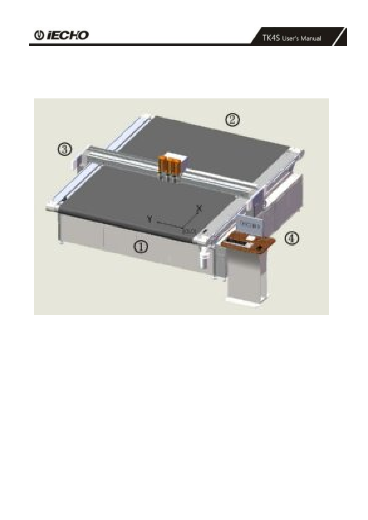
1.7 TK4S Direction Information
Directions such as "right, left" or "front, back" depends on the operator's view of the machine during
operation.
1
front
4
right
2
back
x
X-axis
3
left
Y
Y-axis
8
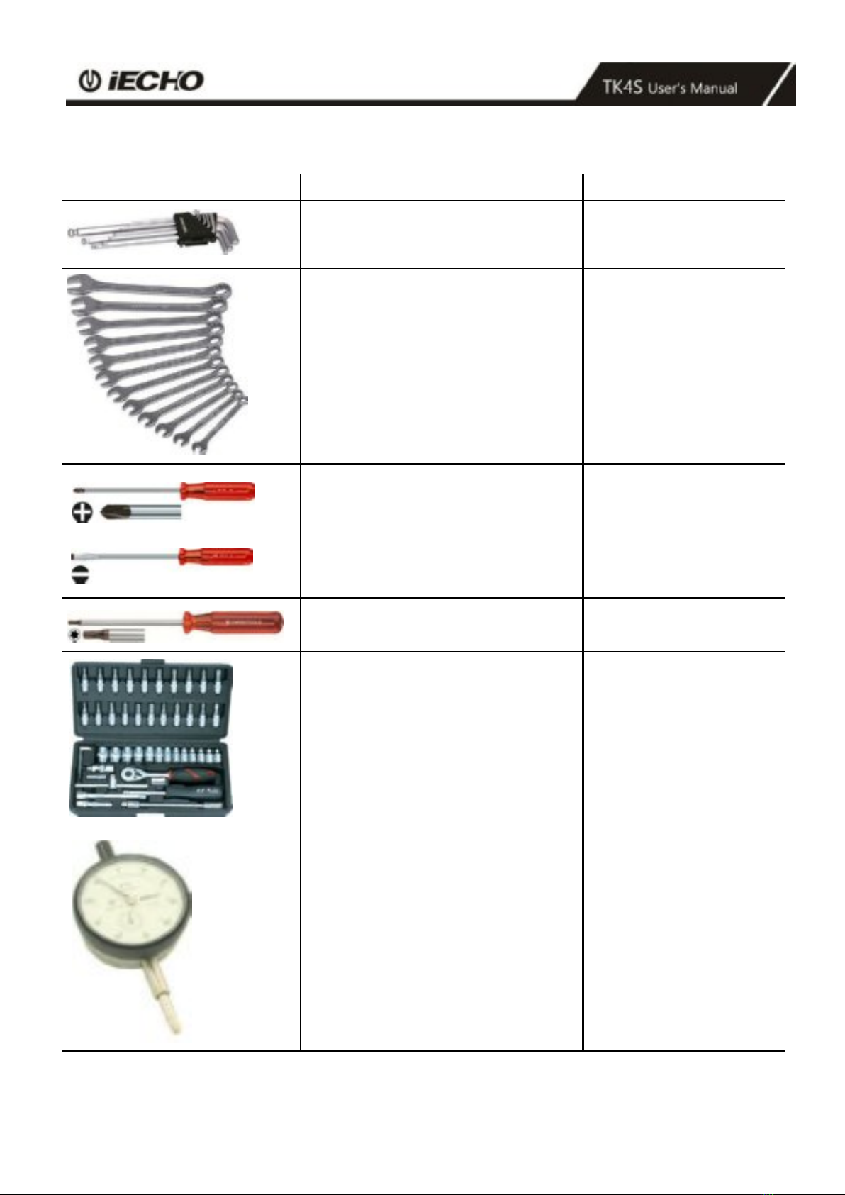
1.8 List of Tools
Illustration
Description
Function
A set of Allen keys (SW 1.5 to 8)
Various open-ended spanners (SW
5.5-19.2x10)
various Phillips and slotted screwdrivers
screwdriver
Ratchet set with bolt nuts and Allen inserts
Dial gauge (resolution of 0.1 mm)
To align the table plate
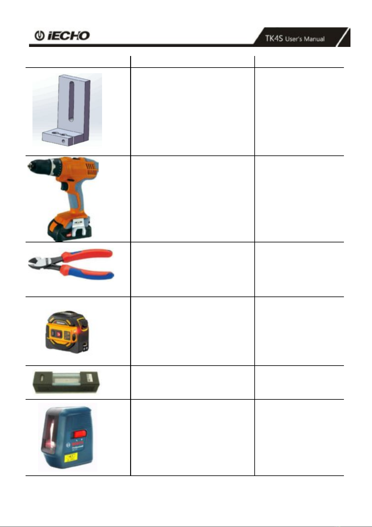
9
Illustration
Description
Function
Holder for supporting dial gauge
Table plate: set height
Electric drill
Side cutters
to open the transport locking
devices
Measuring tape
Precision spirit level (recommended value
0.05 mm/m)
To level the machine
Precision spirit level
To level the machine foot

10
2. Preparation
2.1 Installation Location
Make sure that the following requirements are met:
•the installation location is level and can withstand the floor loads.
•the transportation routes to the installation location do not include steps or staircases.
•the shipping crates can be deposited close to the installation location and their presence does not
prevent the machine from being assembled.
•the aisle width from the unloading location to the installation location is at a minimum the width
required for the dimensions of the packing crates.
•the electrical and air connections meet the requirements listed in the technical data.
•the installation location is well-lit.
•At least 1 meter of space is available all around the cutting system for service and daily operation.
2.2 Personnel
Make sure that the following requirements are met:
•the support personnel wear safety clothing and work gloves.
•the support personnel are familiar with the hazards associated during machine installation and have
read and understood the mounting instructions.
2.3 Power Requirement
Three
-phase
Vacuum
Pump
Voltage
Electric
Current
Air
Circuit
Breaker
Wire
Size
Wiring System
5.5KW
380V
8.3A
20A
6mm²
L1、L2、L3、N、G
7.5KW
380V
12A
20A
6mm²
L1、L2、L3、N、G
Three
-phase
Vacuum
Pump
Voltage
Electric
Current
Air
Circuit
Breaker
Wire
Size
Wiring System
5.5KW
220V
14.5A
30A
6mm²
L1、L2、L3、G
7.5KW
220V
20A
50A
8mm²
L1、L2、L3、G

11
2.4 Environmental Conditions
2.5 Basic Device Compressed Air
2.6 Flooring Space Requirement
Machine Dimension Length X Width (with router, the height of regular route holder is 2.8meter)
2.7 Operation Space Requirement
Machine Dimension: Length X Width (with router, the height of regular route holder is 2.8meter)
Value
Unit
Operating temperature
+ 10 to + 35
°C
Storage temperature
- 20 to + 55
°C
Relative humidity
10 - 80, non-
condensing
%
Conveyor feeding clamps
Value
Units
Operating pressure
0.6
MPA
Min. air flow
0.4
m³/min
Control of POT tool, supply of 1kw,1.8KW
Router
Value
Units
Operating pressure
0.85
MPA
Min. air flow
0.6
m³/min
Material loader
Length / width
TK4S
With
Length
Length+1.9m
Width
Width+0.9m
Without
Length
Length+0.9m
Width
Width+0.9m
Feeding Frame
Length / width
TK4S
With
Length
Length+3.4m
Width
Width+2.4m
Without
Length
Length+2.4m
Width
Width+2.4m

12
3. Installation
3.1 Opening and Inspecting Packing Crates
Note:
Prevent the crate cover from warping when placed at an
angle. Place the packing crate level.
Note:
•Only complete the installation if all parts are present and undamaged.
•Inform IECHO customer service if any parts are missing or damaged.
•Replenish or replace missing or damaged parts.
ARemove all screws on the upper side of the packing crate.
BRemove the cover and place it to one side.
CRemove the screws from the upper crossbars
DRemove the crossbars and place them to one side
ELoosen the screws of the side cover.
FRemove the side cover.
GMake sure the contents are complete and without damage.
13
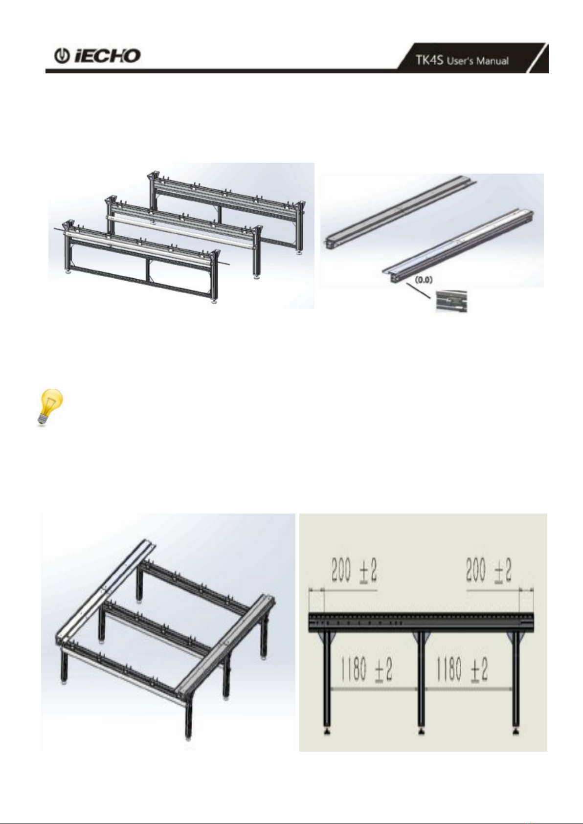
3.2 Setting Up the Base Frame Structure
3.2.1 Framework
The components consists of the left beam, right beam and under frame.
1. Front foot (including pause cable)
2. Middle foot
3. Rear foot Left / Right
Note:
Assemble the left and right beam under frame as below, fasten tightly T-bolts(M8x25mm) with glue, set up the
framework, meet the following requirements:
1. Both side of the end surface distance:200±2mm,adjust the distance between each legs component:1180±2mm。
2. Make sure the diagonal dimensions are less than 2 mm.
TK4S frame
work 1

14
3.2.2 Initial leveling of the base frame
ALift each side support end to keep the balance by precision spirit level.
BDetermine the lowest position of the foot and use the setscrews to adjust it upwards.
CUse the setscrew to raise the position of the lowest foot.

15
3.2.3 Connecting the Pause cables
16
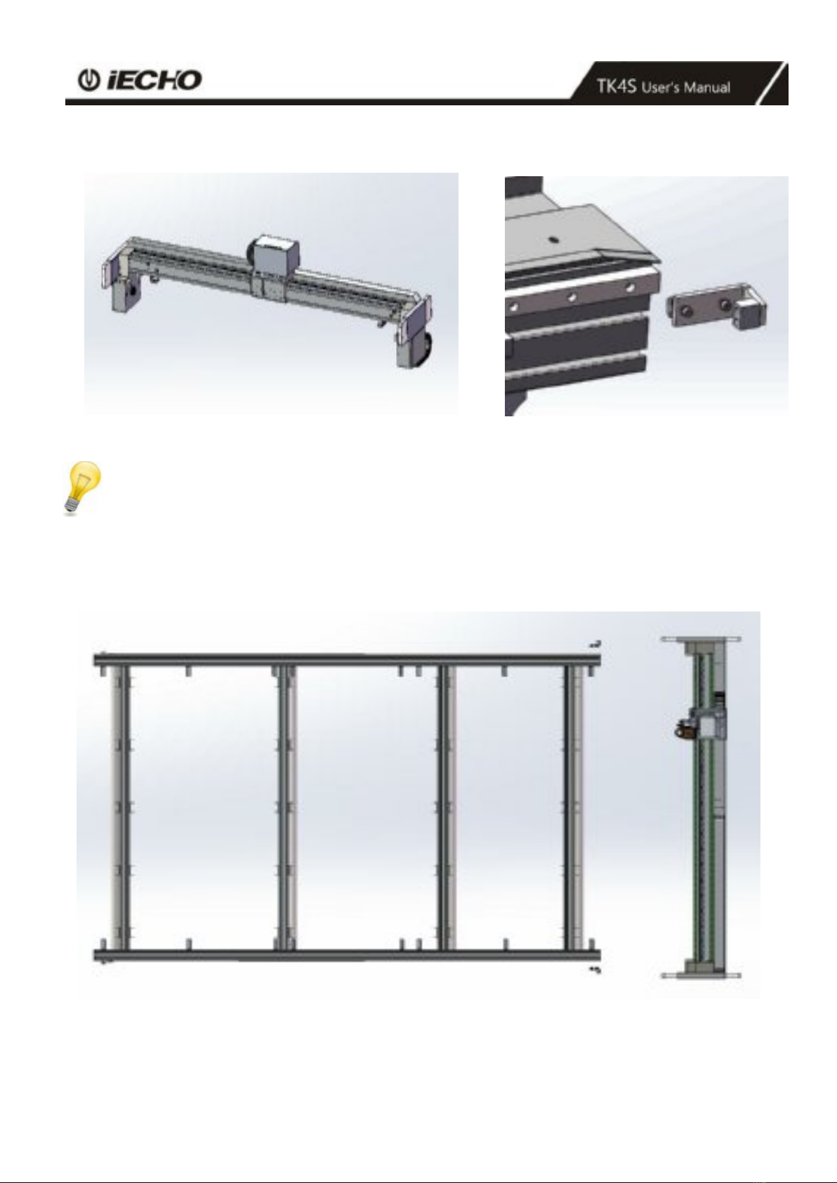
3.3 Assemble the Cutting Beam
Beam Block slider
Pay attention:
Keep balance from rear side when assembling the cutting beam, carefully take out the plug in the slider,
put the cutting beam onto the side beams, make sure that the pen holder faces to the photoelectric plate.
After assembly, put the block slider back and then tighten the screws.
Table of contents
Other IECHO Cutter manuals


