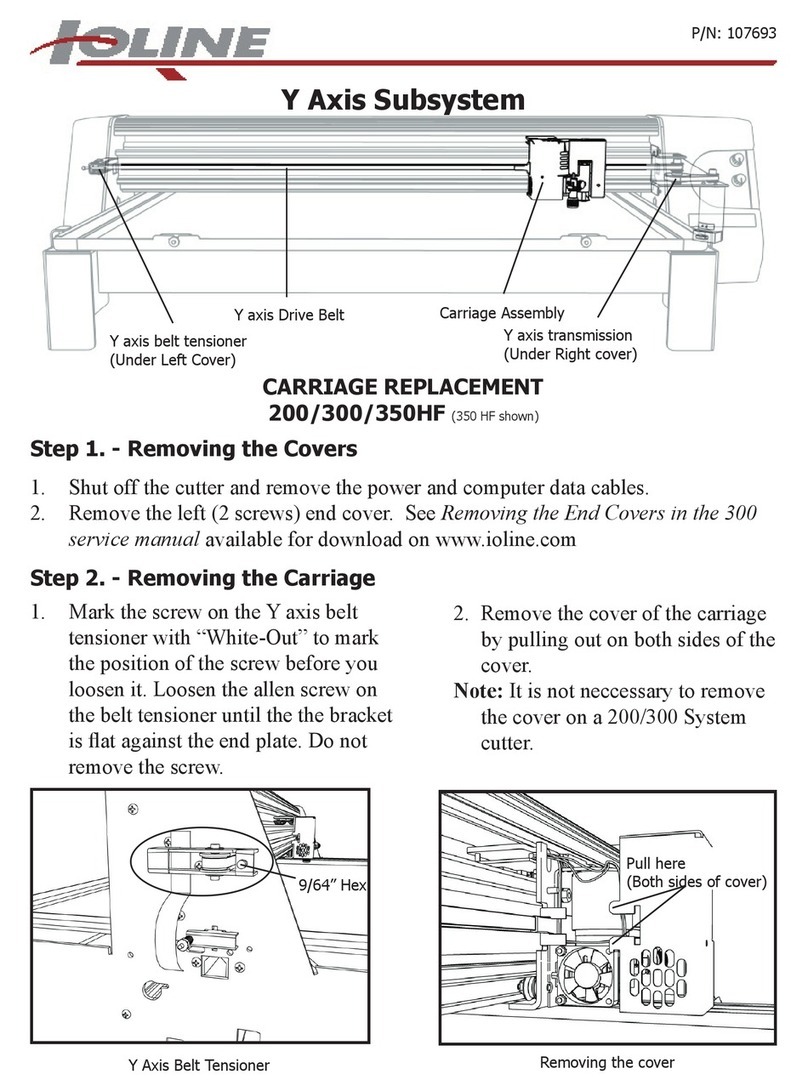
Ioline 300 User manual
Other Ioline Cutter manuals

Ioline
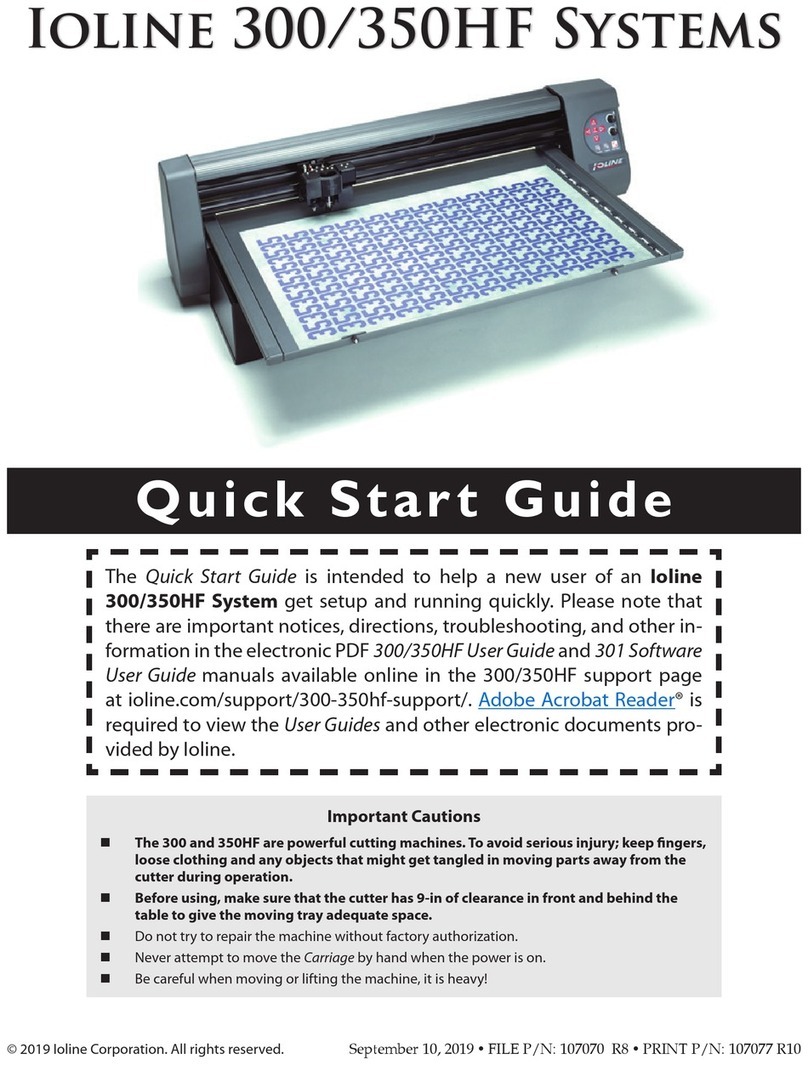
Ioline 350HF User manual

Ioline
Ioline SmarTrac I/S Series User manual

Ioline
Ioline 300 User manual

Ioline
Ioline SmarTrac I/S Installation and operating instructions

Ioline
Ioline SmarTrac 100 Series User manual

Ioline
Ioline SmarTrac 100 Series User manual

Ioline
Ioline 300 User manual

Ioline
Ioline I/S 60 User manual

Ioline
Ioline 350HF User manual
Popular Cutter manuals by other brands

Milwaukee
Milwaukee HEAVY DUTY M12 FCOT Original instructions

SignWarehouse.com
SignWarehouse.com Bobcat BA-60 user manual

Makita
Makita 4112HS instruction manual

GEISMAR STUMEC
GEISMAR STUMEC MTZ 350S manual

Hitachi
Hitachi CM 4SB2 Safety instructions and instruction manual

Dexter Laundry
Dexter Laundry 800ETC1-20030.1 instruction manual


