IECHO 1.8KW Router User manual

1.8KW Router User Manual
1.8KW Router
User Manual
Hangzhou IECHO Science & Technology Co., Ltd.

1.8KW Router User Manual
1
Directory
1. Summary....................................................................................................................................1
2. Caution....................................................................................................................................... 1
3. Mandatory list for 1.8KW debugging.....................................................................................1
4. Inspection before test running................................................................................................1
4.1. Brush......................................................................................................... 1
4.2. Collet......................................................................................................... 1
4.3. Electric and air circuit............................................................................... 2
4.4. Check router cable.....................................................................................2
4.5. Check control cable...................................................................................2
4.6. Check air circuit........................................................................................ 2
4.7. Test run for 1.8kw spindle.........................................................................3
5. Parameter setting..................................................................................................................... 3
6. Manual change router bit (4041)........................................................................................... 6
7. Software setting........................................................................................................................ 6
7.1. Extension parameter..................................................................................6
7.2. Button........................................................................................................6
8. Manual change router bit (4040)........................................................................................... 7
9. Router bit library shifting correction.......................................................................................7
9.1. Component................................................................................................ 7
9.2. Stick & paper to correction router bit library offset................................10
9.3. Read left coordinate of positioning slot A...............................................10
9.4. Read right coordinate of positioning slot A............................................ 10
9.5. Read front coordinate of positioning slot A............................................ 11
9.6. Read back coordinate of positioning slot A.............................................11
9.7. Read coordinate positioning slot B......................................................... 11
9.8. Transfer value from positioning slot to hole........................................... 12
9.9. Positioning hole A/B correction.............................................................. 12
10. Auto change bit test........................................................................................................... 13
Cutterserver setting........................................................................................................................13
10.1. Speed selection........................................................................................13
10.2. Router bit library initialization................................................................13
11. Automatic adjust depth, router bit and pen coincide setting.......................................15
11.1. Reading the coordinates of the initialization point................................. 15
11.2. Router bit and pen coincide.....................................................................16
12. Automatic Tool Changer....................................................................................................17
13. Dust cleaner........................................................................................................................ 18
13.1. Dust cleaner and Router linkage............................................................. 18
13.2. Dust cleaner operation test...................................................................... 19
13.3. Others...................................................................................................... 19
14. Software............................................................................................................................... 20
14.1. Material library........................................................................................20
14.2. Material................................................................................................... 20

1.8KW Router User Manual
2
14.3. Solution................................................................................................... 21
15. IBrightCut............................................................................................................................ 22
16. Export cutting file................................................................................................................26
17. Blade.....................................................................................................................................26
18. Troubleshooting.................................................................................................................. 27
18.1. Emergency stop....................................................................................... 27
18.2. Router cannot be started..........................................................................27
18.3. Router cannot start.................................................................................. 27
18.4. Software serial port in dark status...........................................................27
18.5. The tool library cover is not smooth....................................................... 28
18.6. Blade fall in the tool library.................................................................... 28
19. Software Update.................................................................................................................28
19.1. Serial port connection............................................................................. 28
19.2. Interface configuration............................................................................ 28
Statement....................................................................................................................................... 29

1.8KW Router User Manual
1
1. Summary
This instruction is for R&D testers, factory testers, and engineer. The main
content is 1.8KW milling cutter automatic router bit changer debugging
instructions
2. Caution
Press E-stop button when a security risk appeared.
3. Mandatory list for 1.8KW debugging
Model
List
1
1.8KW router
2
Router bit library
3
TK3S AKI
4
DSP version:2.2.8-6A180903M
5
CutterServer version:V4 - 2019.9.4.51
6
IBrightCut version:V3 - 2019.9.10.194
7
D 9+10mm Stick for initialization
8
9 router bit with rings
9
Test file and configuration.
4. Inspection before test running
4.1. Brush
No brush on spindle when test run.
4.2. Collet
There must be router bit or stick on spindle, run spindle without stick or router
bit is not allowed.

1.8KW Router User Manual
2
4.3.Electric and air circuit
Make sure correct router cable, control cable, air tube connect before test run.
Water cooler: Circulate cooling water inside 1.8kw through inlet and outlet
pipes
4.4.Check router cable
Check router power, controller,( shown in image 1)
(image 1)
4.5.Check control cable
Run testmillingcutter.exe, click START button. Control cable is good if spindle
running, if not, check the connectors.
4.6.Check air circuit.
Main air pressure: 0.8Mpa.
Air pressure for spindle collet: 0.8Mpa
Air pressure for Router bit library: 0.6Mpa
Air pressure for cooling: 0.1Mpa
1.8KW Router User Manual
3
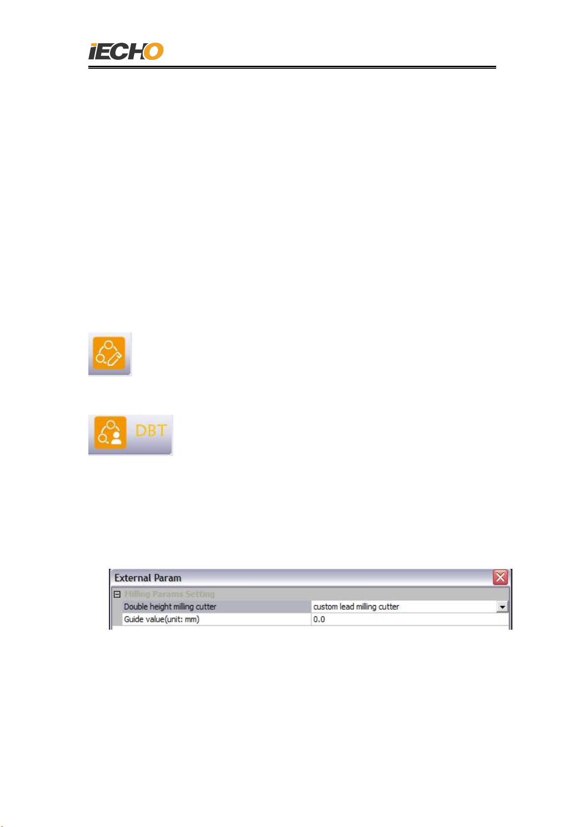
4.7.Test run for 1.8kw spindle.
Run testmillingcutter.exe, (shown in Image 2)
(Image 2)
Parameter setting for software
1. Choose 1.8kw router and select correct serial port.
2. Set the parameter in testmill page, click ON button, spindle run; click
OFF button, spindle closed, set the rotation speed in software, then
spindle rotation speed changed accordingly. (shown in image 3)
3. Do not stop during test run, click Close button to finish test run.
(image 3)
5. Parameter setting
Find extension parameter in Cutterserver (shown in image4)
Start
Close
MILL speed
Sure
Cancel

1.8KW Router User Manual
4
(image 4)
1. IO Function Redefine: define the function of buttons on table.
Change the knife(4 steps: 1. Brush rise; 2. Loose the bit;3. Install router bit;
4. Finish, Brush down)
2. The IO function redefines 1: define the function of buttons on table.
Material thickness detection: After define this function, brush will detect
material thickness once when press the button on table.
3. 2 AKI mode: TK model must be set 2 AKI model(2+2 model), BK model
should be set 2 AKI model (1+1model)
4. Enable tool changing speed: Control cleaning, speed during tool change.
Tick it means select working speed, use for normal running speed.
Untick it means select testing speed, use for testing, all speed is much
lower than working speed.
5. Turn on automatic tool change: Confirm if this model have automatic tool
change or not( select accordingly), after turn on automatic tool change function,
1.8KW Router User Manual
5
machine will go AKI automatically after initialization( Current cutting head no
allowed to be empty)
6. Brush down again depth: this configuration control brush down depth when
cutting, it will affect cutting, dust collection a lot. (The configuration could be
modify by cutter material thickness detect -B MTD)
7. Fine-tune height of brush when cleaning cover: control brush down
compensation when cleaning the cover.
8. Milling blade control way: 1.8KW router use PC, 350W router use C board.
9. Change tool way: 4041 (auto change)/4040(manual change)/4064 (3.6KW
router.)
1kw router/1.8kw router/3.6kw router
For change the router bit, correction shifting.
4040 (Manual change)
make manual change, material thickness detect
3060 (350w): No icon shown.
10. Brush re-depth: After the material thickness is detected, the height of the
brush is compensated (range 0-12.7mm).
External parameter settings (Image 5)
(image 5)

1.8KW Router User Manual
6
6. Manual change router bit (4041)
Move the tool head to manual change position (Shown in image 6):
(image 6)
7. Software setting
7.1.Extension parameter
Modify as follow
Caution: Make sure current head is milling head before manual change.
(image 7)
7.2.Button
TC SLC
Press TC SLC button on table, S: Start;L: Loose; C: Clamp
1. One press, brush down, manual change page pop-up in
cutterserver(shown in image 8).
Remark: The button here have same function as button on table.
2. Two press: The collet loose, take router bit out.
3. Three press: Change router bit, push to bottom, release when clamp.
Click END in cutterserver page after change bit, then brush move on.
Button for manual change:
TC S/L/C
Manual change: Take off the router bit
and change another one.
1.8KW Router User Manual
7
(image 8)
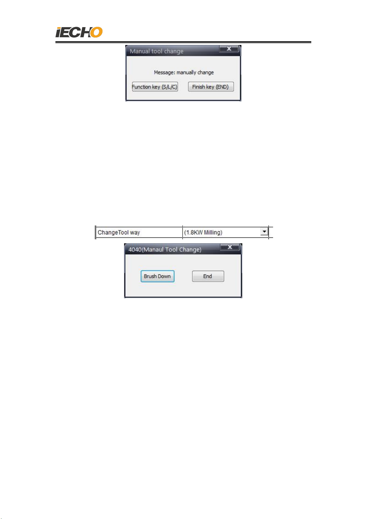
8. Manual change router bit (4040)
Set parameter: modify extension parameter
Click manual change ICON, the following window pop-up.
1. Click【Down brush】, the brush will go down, use wrench to disassembly the
bit.
2. Click END in cutterserver page after change bit, then brush move on.
Caution: DO NOT use software during manual change router bit.
(image 9)
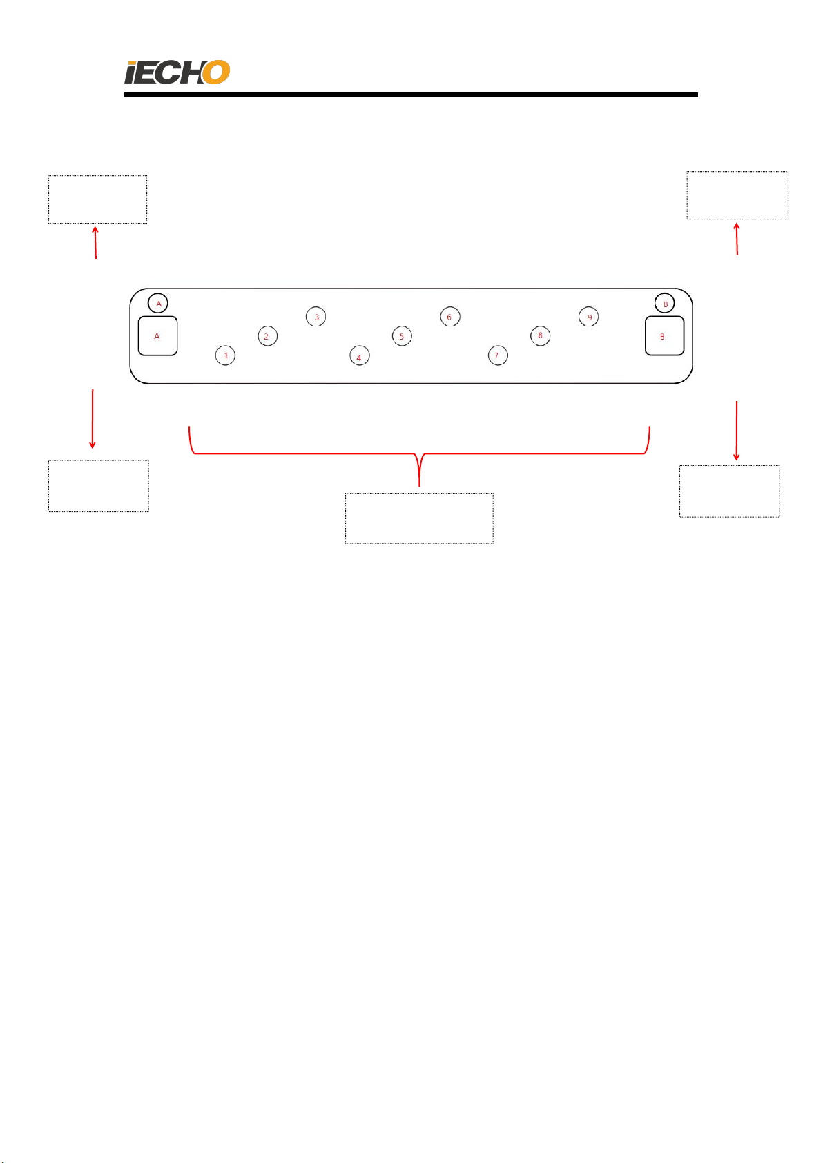
9. Router bit library shifting correction
9.1.Component
Router bit distribution as follow:
1.8KW Router User Manual
8
(Image 10)
CutterServer Auto changer bit page, select shifting correction(router bit library
will open automatically).
9 bit position
Positionin
g Slot A
Positionin
g Slot B
Positioning
hole A
Positioning
hole B
1.8KW Router User Manual
9
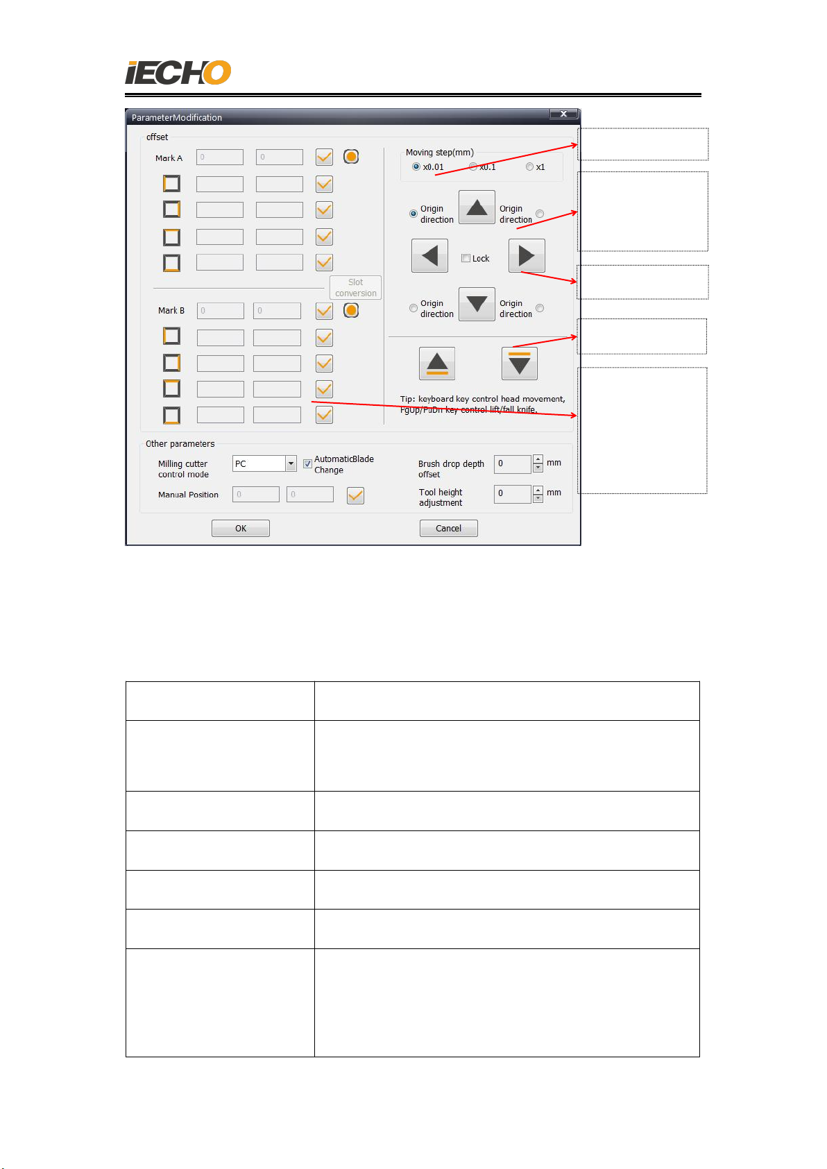
(Image 11)
Function parameters
Meaning
Positioning hole A,
positioning hole B
Coordinate of current saved positioning hole on
table.
Movement step
distance
Tool head movement distance each click.
Coordinate direction
Relationship between movement button and tools
movement.
Router control method
1.8KW router must select”PC control”
Start auto change
Select for current model if with auto changing.
Position for manual
change
If user find the bit not in router bit library when
cutting, move to this position and do manual
change
offset correction
coordinate:
1. left
2. right
3. up
down 边
Up and down
move step distance
Front, back, left, right
Select original position
according to direction of
pc desk and machine

1.8KW Router User Manual
10
Brush down
compensation
After the brush detect material thickness, it will
make down compensation (range 0-12.7mm)
Router bit change
fine-tune
Spindle down compensation when change router
bit (to make extra 2mm down)
9.2.Stick & paper to correction router bit library offset
Preparation
1. Put stick on spindle
2. Cut some 10*40CM paper sheet.
9.3.Read left coordinate of positioning slot A
Set stick to the central position of slot, make sure it fully touch with each side of
slot except bottom side.
Select step distance “x 1mm”, move the stick approach to left side of slot;
change to step distance”x0.1mm”, put paper between stick and left side of slot,
keep moving stick till paper can’t move up and down, then back 0.1mm,
change to step distance”x0.01mm”, keep moving when paper can’t be move
up and down, read the coordinate.
Read the coordinate and click
9.4. Read right coordinate of positioning slot A
Set stick to the central position of slot, make sure it fully touch with each
side of slot except bottom side.
Select step distance “x 1mm”, move the stick approach to right side of slot;
change to step distance”x0.1mm”, put paper between stick and right side of
slot, keep moving stick till paper can’t move up and down, then back 0.1mm,
change to step distance”x0.01mm”, keep moving when paper can’t be move
up and down, read the coordinate.

1.8KW Router User Manual
11
Read the coordinate and click
9.5. Read front coordinate of positioning slot A
Set stick to the central position of slot, make sure it fully touch with each
side of slot except bottom side.
Select step distance “x 1mm”, move the stick approach to front side of slot;
change to step distance”x0.1mm”, put paper between stick and front side of
slot, keep moving stick till paper can’t move up and down, then back 0.1mm,
change to step distance”x0.01mm”, keep moving when paper can’t be move
up and down, read the coordinate.
Read the coordinate and click
9.6. Read back coordinate of positioning slot A
Set stick to the central position of slot, make sure it fully touches with each side of slot
except bottom side.
Select step distance “x 1mm”, move the stick approach to back side of slot; change to
step distance”x0.1mm”, put paper between stick and back side of slot, keep moving stick
till paper can’t move up and down, then back 0.1mm, change to step distance”x0.01mm”,
keep moving when paper can’t be move up and down, read the coordinate.
Read the coordinate and click
9.7.Read coordinate positioning slot B
After read coordinate of four side, click “W”to lift the stick to top, move tool
head to positioning B slot, read coordinate of four side with same way, lift the
stick to the top(shown in image 12)

1.8KW Router User Manual
12
(image 12)
9.8.Transfer value from positioning slot to hole.
After read coordinate of 8 side of two slot, click OK, the software will
calculator and transfer value from positioning slot to hole, click OK save to
DSP.
9.9.Positioning hole A/B correction
Open offset correction page again, click the ICON behind of positioning hole A,
tool head will move to the top of positioning hole A and down slowly, check if
the 10mm stick could fit the hole completely, if yes, lift the tool head and
correct positioning hole B offset. After correct offset of AB coordinate then do
auto change test. (If any offset during correction, need to correct A and B slot
coordinate or fine-tune hole coordinate)

1.8KW Router User Manual
13
10.Auto change bit test.
Cutterserver setting
10.1. Speed selection
There are two speed in auto change setting, normal running speed and
test speed; untick working speed in extension parameter, then it will be test
speed.
10.2. Router bit library initialization.
1. Select router head and click CT ICON, select modify router bit page
(router bit library will open)
2. Put router bit into library, select right bit number in software with
accordingly.
(image 13)
2Other operation
1.8KW Router User Manual
14
(image 14)
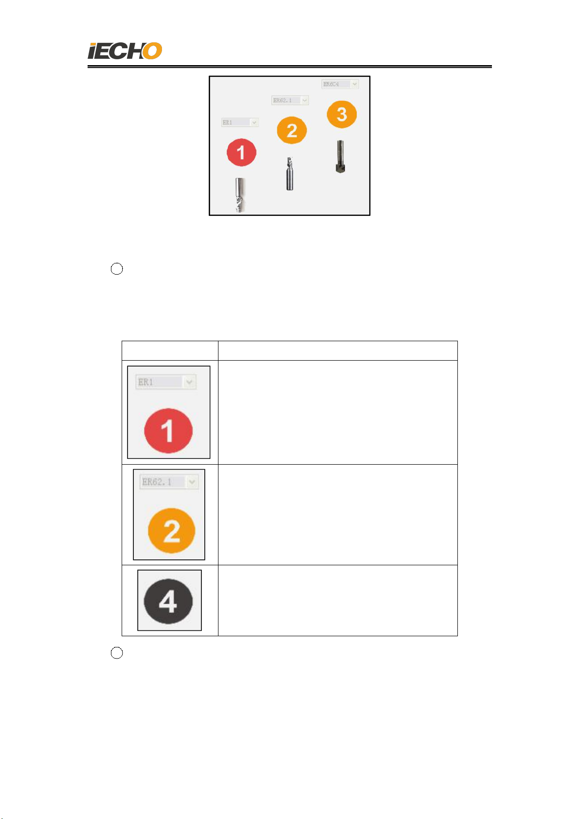
3Instruction for image in library
Image
Meaning
Means no.1 holder is current holder, and
ER1 blade on current holder, new router bit
not allowed to put on this holder.
Means No.2 holder is not empty, with router
bit ER62.1
Means No.4 holder is empty and could set
any router bit.
4Click SAVE after configure finished, click OK to finish router bit library
initialization after make sure all configuration correct.

1.8KW Router User Manual
15
(image 15)
11. Automatic adjust depth, router bit and pen coincide
setting.
11.1. Reading the coordinates of the initialization point
1. Select router head, open CT to offset correction page.
2. Move tool head to AKI position, and down router bit to confirm.
3. Write down current coordinate (X,Y), then quit CT page.
4. Choose system configuration-AKI-first AKI point, move router head to
(X, Y) position.
5. After click SAVE, use AKI testing, start adjust the cutting depth after
confirm the position.(Tick”Check sensor before adjustment “when first
adjustment) . Use finger to shade the AKI back and forth after tick it.

1.8KW Router User Manual
16
(image 16)
(image 17)
11.2. Router bit and pen coincide
1. Use chamfering bit when test coincide of router bit and pen.
2. Open coincide test file(shown in image 18)
3. Output the file and cut, modify the offset parameter to correct
position(shown in image 19).
Remarks: Do not modify router head offset because it will affect the AKI
position, router change position etc.)

1.8KW Router User Manual
17
(image 18)
(image 19)
12.Automatic Tool Changer
Send file, click the start button, perform automatic tool change, observe
whether each milling cutter blade is changing normally. If it is dangerous, press
the emergency stop button immediately.
Testing method:
Open the test data in IBrightCut, including 9 blade automatic tool change data,
use manual to start cutting, such as (image 20):
Table of contents
Other IECHO Wood Router manuals

Popular Wood Router manuals by other brands


Mafell
Mafell LO 65 Ec Translation of the original operating instructions

Festool
Festool Plunge Router I instruction manual

Far Tools
Far Tools ER 700 manual

Scheppach
Scheppach WRT1200 Translation of original instruction manual

Westfalia
Westfalia WOF 1600 Original instructions

EINHELL
EINHELL TC-RO 850 Original operating instructions


