iEi Integration Corp. POC-17i User manual

POC-17i/19i Series
Page i
User Manual
MODEL:
POC-17i/19i Series
Medical Panel PC with Intel® Core™ i7/i5/i3 Processor,
TFT LCD, Wireless LAN, Touch Screen,
RS-232/422/485 and RoHS
Rev. 1.01 – June 30, 2016

POC-17i/19i Series
Page iii
Copyright
COPYRIGHT NOTICE
The information in this document is subject to change without prior notice in order to
improve reliability, design and function and does not represent a commitment on the part
of the manufacturer.
In no event will the manufacturer be liable for direct, indirect, special, incidental, or
consequential damages arising out of the use or inability to use the product or
documentation, even if advised of the possibility of such damages.
This document contains proprietary information protected by copyright. All rights are
reserved. No part of this manual may be reproduced by any mechanical, electronic, or
other means in any form without prior written permission of the manufacturer.
TRADEMARKS
All registered trademarks and product names mentioned herein are used for identification
purposes only and may be trademarks and/or registered trademarks of their respective
owners.

POC-17i/19i Series
Page iv
Manual Conventions
WARNING
Warnings appear where overlooked details may cause damage to the
equipment or result in personal injury. Warnings should be taken
seriously.
CAUTION
Cautionary messages should be heeded to help reduce the chance of
losing data or damaging the product.
NOTE
These messages inform the reader of essential but non-critical
information. These messages should be read carefully as any directions
or instructions contained therein can help avoid making mistakes.
HOT SURFACE
This symbol indicates a hot surface that should not be touched without
taking care.
OPERATING INSTRUCTION
Follow operating instructions or consult instructions for use.

POC-17i/19i Series
Page v
Contact Information
Headquarters
IEI Integration Corp.
Address: No. 29, Zongxing Rd., Xizhi Dist.,
New Taipei City 221, Taiwan
Phone: +886-2-8691-6798
Fax: +886-2-6616-0028
Web Site: www.ieiworld.com
USA
IEI Integration USA Corp.
Address: 138 University Parkway,
Pomona, CA 91768
Phone: +1-909-595-2819
Fax: +1-909-595-2816
Web Site: www.ieiworld.com

POC-17i/19i Series
Page vi
Table of Contents
1 INTRODUCTION.......................................................................................................... 1
1.1 OVERVIEW.................................................................................................................. 2
1.2 FEATURES................................................................................................................... 3
1.3 EXTERNAL OVERVIEW................................................................................................ 3
1.3.1 General Description........................................................................................... 3
1.3.2 Front Panel ........................................................................................................ 3
1.3.3 Rear Panel ......................................................................................................... 4
1.3.4 I/O Interface Panel ............................................................................................ 5
1.3.5 OSD Control Buttons ......................................................................................... 6
1.4 INTERNAL OVERVIEW................................................................................................. 6
1.5 SYSTEM SPECIFICATIONS............................................................................................ 7
1.6 DIMENSIONS............................................................................................................... 9
2 UNPACKING................................................................................................................11
2.1 UNPACKING.............................................................................................................. 12
2.2 PACKING LIST........................................................................................................... 13
3 INSTALLATION ......................................................................................................... 15
3.1ANTI-STATIC PRECAUTIONS...................................................................................... 16
3.2 INSTALLATION PRECAUTIONS................................................................................... 16
3.3 INSTALLATION AND CONFIGURATION STEPS ............................................................. 17
3.4 REMOVING THE REAR PANEL COVER ....................................................................... 17
3.5 REMOVING THE INTERNALALUMINUM COVER ........................................................ 18
3.6 JUMPER SETTINGS .................................................................................................... 19
3.6.1 Access the Jumpers.......................................................................................... 20
3.6.2 Preconfigured Jumpers.................................................................................... 20
3.6.3 Clear CMOS Jumper........................................................................................ 21
3.6.4 COM1 Pin 9 Setting......................................................................................... 22
3.6.5 COM3 TX Function Select Jumper.................................................................. 24
3.6.6 COM3 RS-232/422/485 Jumper....................................................................... 25

POC-17i/19i Series
Page vii
3.6.6.1 COM3 RS-422 and RS-485 Pinouts......................................................... 26
3.6.7 COM3 RS Function Select Jumper.................................................................. 27
3.6.8 ME Debug Mode Jumper................................................................................. 28
3.6.9 iTPM Setting Jumper ....................................................................................... 29
3.6.10 ME RTC Select Jumper.................................................................................. 30
3.6.11 SPI Setting Jumper......................................................................................... 31
3.7 MOUNTING THE SYSTEM .......................................................................................... 32
3.7.1 Wall Mounting.................................................................................................. 32
3.7.2 Arm Mounting .................................................................................................. 35
3.8 BOTTOM PANEL CONNECTORS ................................................................................. 36
3.8.1 LAN Connection............................................................................................... 36
3.8.2 Serial Device Connection ................................................................................ 37
3.8.3 USB Device Connection................................................................................... 38
3.8.4 VGA Monitor Connection ................................................................................ 39
3.9AT/ATX MODE SELECTION...................................................................................... 40
3.9.1 AT Power Mode................................................................................................ 41
3.9.2 ATX Power Mode............................................................................................. 41
4 SYSTEM MAINTENANCE ....................................................................................... 42
4.1 SYSTEM MAINTENANCE INTRODUCTION.................................................................. 43
4.2ANTI-STATIC PRECAUTIONS...................................................................................... 43
4.3 TURN OFF THE POWER.............................................................................................. 44
4.4 REPLACING COMPONENTS........................................................................................ 44
4.4.1 Memory Module Replacement ......................................................................... 44
4.4.2 HDD Card Replacement.................................................................................. 46
5 BIOS SETUP................................................................................................................ 49
5.1 INTRODUCTION......................................................................................................... 50
5.1.1 Starting Setup................................................................................................... 50
5.1.2 Using Setup...................................................................................................... 50
5.1.3 Getting Help..................................................................................................... 51
5.1.4 Unable to Reboot After Configuration Changes.............................................. 51
5.1.5 BIOS Menu Bar................................................................................................ 51
5.2 MAIN........................................................................................................................ 52
5.3ADVANCED............................................................................................................... 53

POC-17i/19i Series
Page viii
5.3.1 ACPI Settings................................................................................................... 54
5.3.2 Trusted Computing........................................................................................... 55
5.3.3 CPU Configuration.......................................................................................... 56
5.3.4 SATA Configuration ......................................................................................... 57
5.3.5 USB Configuration........................................................................................... 58
5.3.6 Super IO Configuration ................................................................................... 59
5.3.6.1 Serial Port n Configuration....................................................................... 60
5.3.7 H/W Monitor.................................................................................................... 64
5.3.8 Serial Port Console Redirection ...................................................................... 65
5.4 CHIPSET ................................................................................................................... 66
5.4.1 Northbridge Configuration.............................................................................. 67
5.4.2 Southbridge Configuration .............................................................................. 68
5.4.3 Intel IGD SWSCI OpRegion............................................................................. 69
5.5 BOOT........................................................................................................................ 71
5.6 SECURITY................................................................................................................. 72
5.7 EXIT......................................................................................................................... 73
6 SOFTWARE DRIVERS.............................................................................................. 75
6.1AVAILABLE SOFTWARE DRIVERS .............................................................................. 76
6.2 CHIPSET DRIVER INSTALLATION............................................................................... 76
6.3 VGADRIVER INSTALLATION.................................................................................... 80
6.4 LAN DRIVER INSTALLATION.................................................................................... 84
6.5AUDIO DRIVER INSTALLATION ................................................................................. 86
6.5.1 BIOS Setup....................................................................................................... 86
6.5.2 Driver Installation ........................................................................................... 86
6.6 TOUCH SCREEN DRIVER........................................................................................... 90
6.7 WIRELESS DRIVER ................................................................................................... 92
6.8 KEYPAD DRIVER ...................................................................................................... 95
A SAFETY PRECAUTIONS....................................................................................... 100
A.1 SAFETY PRECAUTIONS .......................................................................................... 101
A.1.1 General Safety Precautions........................................................................... 101
A.1.2 Explanation of Graphical Symbols................................................................ 102
A.1.3 Anti-static Precautions .................................................................................. 103
A.1.4 Product Disposal........................................................................................... 104

POC-17i/19i Series
Page ix
A.2 MAINTENANCE AND CLEANING PRECAUTIONS...................................................... 104
A.2.1 Maintenance and Cleaning............................................................................ 104
A.2.2 Cleaning Tools............................................................................................... 105
A.3 FCC PRECAUTIONS ............................................................................................... 106
B BIOS OPTIONS ........................................................................................................ 107
B.1 BIOS CONFIGURATION OPTIONS ........................................................................... 108
C WATCHDOG TIMER ...............................................................................................110
D HAZARDOUS MATERIALS DISCLOSURE........................................................113

POC-17i/19i Series
Page x
List of Figures
Figure 1-1: POC-17i/19i Series Medical Panel PC .......................................................................2
Figure 1-2: Front View....................................................................................................................4
Figure 1-3: Rear View.....................................................................................................................4
Figure 1-4: I/O Interface Connector Panel....................................................................................5
Figure 1-5: OSD Control Buttons..................................................................................................6
Figure 1-6: POC-17i Series Dimensions (mm).............................................................................9
Figure 1-7: POC-17i Series Dimensions (mm)...........................................................................10
Figure 3-1: Back Cover Retention Screws.................................................................................18
Figure 3-2: Aluminum Back Cover Retention Screws ..............................................................19
Figure 3-3: Clear CMOS Jumper .................................................................................................22
Figure 3-4: JP7 Jumper Setting Location ..................................................................................23
Figure 3-5: JP8 Jumper Setting Location ..................................................................................24
Figure 3-6: COM3 TX Function Select Jumper Location..........................................................25
Figure 3-7: COM3 RS-232/422/485 Serial Port Select Jumper Location..................................26
Figure 3-8: COM3 RX Function Select Jumper Location..........................................................28
Figure 3-9: ME Debug Mode Jumper Location..........................................................................29
Figure 3-10: iTPM Jumper Location............................................................................................30
Figure 3-11: ME RTC Jumper Location ......................................................................................31
Figure 3-12: SPI Jumper Location ..............................................................................................32
Figure 3-13: Wall-mounting Bracket...........................................................................................33
Figure 3-14: Chassis Support Screws........................................................................................34
Figure 3-15: Securing the Panel PC............................................................................................35
Figure 3-16: Arm Mounting Retention Screw Holes..................................................................36
Figure 3-17: LAN Connection......................................................................................................37
Figure 3-18: Serial Device Connector.........................................................................................38
Figure 3-19: USB Device Connection.........................................................................................39
Figure 3-20: VGA Connector .......................................................................................................40
Figure 3-21: AT/ATX Switch Location.........................................................................................40
Figure4-1: HDD Bracket Screws..................................................................................................45
Figure 4-2: SO-DIMM Socket Location .......................................................................................45

POC-17i/19i Series
Page xi
Figure 4-3: DDR SO-DIMM Module Installation..........................................................................46
Figure 4-4: HDD Cover Screw......................................................................................................47
Figure 4-5: HDD Bracket Retention Screw.................................................................................47
Figure 4-6: HDD Removal ............................................................................................................48
Figure 6-1: Chipset Driver File Extraction Screen.....................................................................77
Figure 6-2: Chipset Driver Welcome Screen..............................................................................77
Figure 6-3: Chipset Driver License Agreement.........................................................................78
Figure 6-4: Readme File Information Screen.............................................................................78
Figure 6-5: Setup Progress Screen.............................................................................................79
Figure 6-6: Chipset Driver Installation Finish Screen...............................................................79
Figure 6-7: VGA Driver Readme File...........................................................................................80
Figure 6-8: VGA Driver Setup File Extraction Screen...............................................................81
Figure 6-9: VGA Driver Welcome Screen...................................................................................81
Figure 6-10: VGA Driver License Agreement.............................................................................82
Figure 6-11: VGA Driver Readme File.........................................................................................82
Figure 6-12: VGA Driver Setup Operations................................................................................83
Figure 6-13: VGA Driver Setup Is Complete Screen .................................................................83
Figure 6-14: LAN Driver Welcome Screen .................................................................................84
Figure 6-15: LAN Driver Welcome Screen .................................................................................85
Figure 6-16: LAN Driver Installation ...........................................................................................85
Figure 6-17: LAN Driver Installation Complete..........................................................................86
Figure 6-18: The InstallShield Wizard Starts .............................................................................87
Figure 6-19: Preparing Setup Screen .........................................................................................87
Figure 6-20: InstallShield Wizard Welcome Screen ..................................................................88
Figure 6-21: Audio Driver Progress Screen...............................................................................88
Figure 6-22: Installation Wizard Updates the System...............................................................89
Figure 6-23: Restart the Computer .............................................................................................89
Figure 6-24: PenMount Welcome Screen...................................................................................90
Figure 6-25: License Agreement.................................................................................................91
Figure 6-26: Choose Install Location..........................................................................................91
Figure 6-27: Installing PenMount Universal Driver V2.1.0.263.................................................92
Figure 6-28: PenMount Universal Driver Update Complete .....................................................92
Figure 6-29: Wireless Driver License Agreement......................................................................93
Figure 6-30: Wireless Driver Configuration Tool Options........................................................94
Figure 6-31: Wireless Mode Select Window ..............................................................................94

POC-17i/19i Series
Page xii
Figure 6-32: Wireless Driver Installation....................................................................................95
Figure 6-33: Keypad Driver Welcome Screen............................................................................96
Figure 6-34: Customer Information Screen ...............................................................................96
Figure 6-35: Setup Type...............................................................................................................97
Figure 6-36: Ready to Install the Program .................................................................................97
Figure 6-37: Installing KeypadAP v2.2 .......................................................................................98
Figure 6-38: Keypad Driver Installation Complete Screen.......................................................98
Figure 6-39: Reboot the Computer .............................................................................................99

POC-17i/19i Series
Page xiii
List of Tables
Table 1-1: System Specifications..................................................................................................8
Table 3-1: Jumpers.......................................................................................................................20
Table 3-2: Preconfigured Jumpers .............................................................................................21
Table 3-3: Clear CMOS Jumper Settings....................................................................................21
Table 3-4: COM1 Pin 9 Setting Jumper Settings.......................................................................22
Table 3-5: COM3 Pin 9 Setting Jumper Settings.......................................................................23
Table 3-6: COM3 TX Function Select Jumper Settings.............................................................24
Table 3-7: COM3 RS-232/422/485 Serial Port Select Jumper Settings....................................26
Table 3-8: RS-422 Pinouts ...........................................................................................................26
Table 3-9: RS-485 Pinouts ...........................................................................................................27
Table 3-10: COM3 RX Function Select Jumper Settings..........................................................27
Table 3-11: ME Debug Mode Jumper Settings ..........................................................................28
Table 3-12: iTPM Jumper Settings..............................................................................................29
Table 3-13: ME RTC Jumper Settings.........................................................................................30
Table 3-14: SPI Jumper Settings.................................................................................................31
Table 5-1: BIOS Navigation Keys................................................................................................51

POC-17i/19i Series
Page xiv
BIOS Menus
BIOS Menu 1: Main.......................................................................................................................52
BIOS Menu 2: Advanced..............................................................................................................54
BIOS Menu 3: ACPI Configuration..............................................................................................54
BIOS Menu 4: TPM Configuration...............................................................................................55
BIOS Menu 5: CPU Configuration...............................................................................................56
BIOS Menu 6: IDE Configuration.................................................................................................57
BIOS Menu 7: USB Configuration...............................................................................................58
BIOS Menu 8: Super IO Configuration........................................................................................59
BIOS Menu 9: Serial Port n Configuration Menu.......................................................................60
BIOS Menu 10: Hardware Health Configuration........................................................................64
BIOS Menu 11: Serial Port Console Redirection.......................................................................65
BIOS Menu 12: Chipset................................................................................................................66
BIOS Menu 13: Northbridge Chipset Configuration..................................................................67
BIOS Menu 14: Southbridge Chipset Configuration.................................................................68
BIOS Menu 15: Intel IGD SWSCI OpRegion ...............................................................................69
BIOS Menu 16: Boot.....................................................................................................................71
BIOS Menu 17: Security...............................................................................................................72
BIOS Menu 18: Exit.......................................................................................................................73

POC-17i/19i Series
Page 1
Chapter
1
1 Introduction

POC-17i/19i Series
Page 2
1.1 Overview
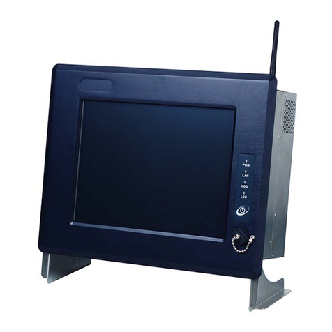
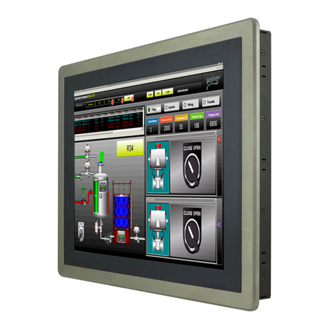
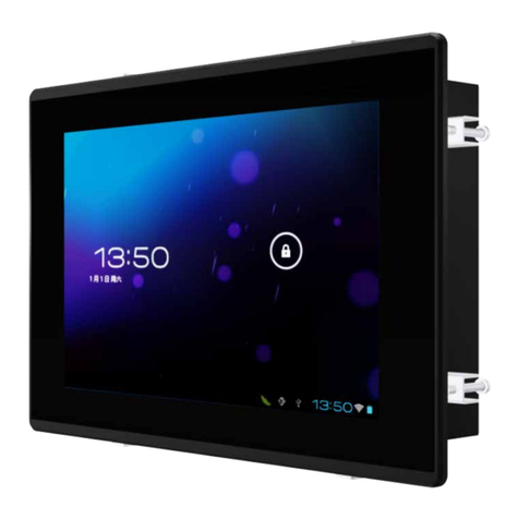
Figure 1-1: POC-17i/19i Series Medical Panel PC
The POC-17i/19i Series is an Intel® Core™ powered flat panel PC with a rich variety of
functions and peripherals. All POC-17i/19i Series models are designed for easy and
simplified integration into point-of-care (POC) applications.
An Intel® Core™ i7/i5/i3 processor coupled with the Intel® HM55 chipset delivers optimal
memory, graphics, and peripheral I/O support. The system comes with 2.0 GB of
preinstalled DDR3 dual-channel SO-DIMMs and supports a maximum of 8.0 GB ensuring
smooth data throughputs with reduced bottlenecks and fast system access. The
POC-17i/19i Series features a Gen 5.7 Enhanced Graphics Engine with 12 execution units
and DirectX 10 and Open GL 2.1 support for high quality video performance. Dual display
support is provided via VGA and HDMI ports.
Two serial ports and four external USB 2.0 ports provide simplified connectivity to a variety
of external peripheral devices. Wi-Fi capabilities and two RJ-45 GbE connectors allow for
smooth connection of the system to an external LAN. The POC-17i/19i Series also
supports a 2.5” SATA HDD drive which can be accessed without removing the entire back
panel.

POC-17i/19i Series
Page 3
Intended use: The POC-17i/19i Series is intended to serve as a medical computing device
for integration with hospital system. It is designed for general purpose for hospital
environment. For data collection and display for reference. It shall not be used for
life-supporting system.
1.2 Features
The POC-17i/19i Series features the following:
Intel® Core™ i7/i5/i3 processor
Intel® HM55 chipset
2.0 GB DDR3 SO-DIMM preinstalled
802.11 a/b/g/n wireless module
Four USB 2.0 ports
Watchdog timer that triggers a system reset if the system hangs for some
reason
AT or ATX power mode
Touch screen
RoHS compliance
1.3 External Overview
1.3.1 General Description
The stylish POC-17i/19i Series panel PC is comprised of a screen, rear panel and bottom
panel. An anti-bacteria plastic front frame surrounds the front screen. The rear panel
provides screw holes for a wall-mounting bracket compliant with VESA FDMI standard. An
I/O interface on the bottom panel provides access to external interface connectors that
include LAN, USB 2.0, serial port, reset button, VGA, HDMI, audio connector, power
connector, power switch and AT/ATX mode switch. The right side panel provides access
to a SATA HDD drive.
1.3.2 Front Panel
The front side of the POC-17i/19i Series is a flat panel TFT LCD screen surrounded by an
anti-bacteria plastic frame. The power LED is located at the top center of the front panel
(Figure 1-2).

POC-17i/19i Series
Page 5
1.3.4 I/O Interface Panel
The I/O interface panel located on the bottom of the POC-17i/19i Series has the following
I/O interface connectors:
1 x Power switch
1 x 12 V DC In connector
1 x RS-232 connector
1 x RS-232/422/485 connector
2 x RJ-45 for Giga LAN connectors
1 x AT/ATX power mode switch
4 x USB 2.0 connectors
1 x HDMI connector
1 x Audio line-out connector
1 x VGA connector
1 x Reset button
The external I/O interface connector panel is shown in Figure 1-4.
Figure 1-4: I/O Interface Connector Panel

POC-17i/19i Series
Page 6
1.3.5 OSD Control Buttons
The POC-17i/19i Series has seven OSD control buttons as shown below.
Figure 1-5: OSD Control Buttons
1.4 Internal Overview
The POC-17i/19i Series has the following components installed internally:
1 x Mainboard
1 x 2.0 GB 800/1066 MHz DDR3 SO-DIMM
1 x Wireless module
1 x 320GB SATA HDD
This manual suits for next models
1
Table of contents


