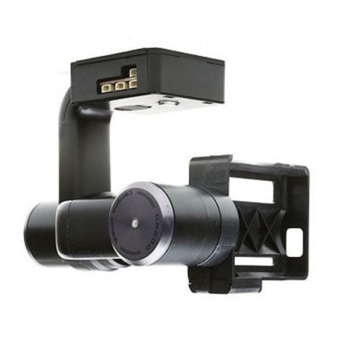
Iflight DOLLA BMCC User manual

Dolla BMCC User's Manual
© 2014 IFLIGHT-RC. All Rights Reserved. 1
V1.0 2014.08
Dolla BMCC User's Manual
LIST OF ITEMS
Dolla BMCC Handheld Gimbal * 1pcs
B6 charger * 1pcs
LiPo Battery * 1pcs
USB cable * 1pcs
User's Manual * 1pcs

© 2014 IFLIGHT-RC. All Rights Reserved. 2
Dolla BMCC User's Manual
Technical Description
Product name: Dolla BMCC
Product type: 3-axis brushless gimbal
Product Description:
The Dolla BMCC is a 3-axis brushless gimbal with an interchangeable feature allowing it to function either in an
airborne application or a handheld gimbal — simply by changing the mounting racks. It also features an independent
self-stabilization function, not relying on the airframe flight controller or other external control systems. In airborne
mode, it uses an internal secondary stabilization system to further stability itself while in flight.
This gimbal is made of 6061-T6 aerospace aluminum, and is sculpted with precision CNC machining. The gimbal
uses custom designed and developed high-torque brushless motors to maximize both gripping power and control
accuracy, enabling it to support heavier cameras and high wind conditions. With its vibration dampening system,
slip-ring equipped motors, and internal wiring — this gimbal rotates around all three axes with unimpeded freedom and
smoothness. Having the added ability of the yaw motor to endlessly pan 360 degrees, this gimbal is exclusively built to
meet all the needs of a variety of video or photography challenges.
Designed with the AV and image transmission interface, this gimbal can easily utilize the connection between the
camera and image transmission. Equipped with an infrared module, this gimbal can support Panasonic GH2,3,4 series
cameras to take pictures and video.
Product weight: 1100g (batteries and handheld kit not included)
Shooting modes: Six receiver channels available (Product does not include a receiver)
Supported cameras: Black Magic Cinema Camera(BMCC 2.5K),Black Magic Production Cinema(BMPC
4K)
Supported lens: 24mm,17-40mm, and other lens with suitable weight
Built-in functions: Bluetooth wireless Module
Control Channel: Six receiver channels available (Product does not include a receiver)
Rotation angles: Pitch axis control angle: 360 degrees
Roll axis control angle: 160 degrees
Yaw axis control angle: 360 degrees
Operating Voltage: 24V(6S)
Other features: High strength,light in weight

Gimbal Desciption
Dolla BMCC Front View
Dolla BMCC User's Manual
©2014 IFLIGHT-RC.All Rights Reserved. 3

Gimbal Desciption
One-HandedHandgrip
Handgrip
YAW MOTOR GBM8017
32BIT alemos bgc
Powerconnector
Handgrip
Joystick control
power switch ON/OFF
Dolla BMCC Rear View
Dolla BMCC User's Manual
©2014 IFLIGHT-RC.All Rights Reserved. 4

© 2014 IFLIGHT-RC. All Rights Reserved. 5
Mounting Camera
Place the camera on the camera tray with lens placed through openning in the front panel, and attach the camera
to the mounting plate with the screw provided, allowing adequate space around camera/lens. With the locking screw
slightly loose, adjust the camera position from front to rear, while keeping the lens and lens mounting hole concentric.
Make sure the camera and the front panel can rotate freely when hands are removed from the camera.
Notice the center of gravity (CoG) changing while moving the camera from front to rear. If lens sinks down, it
means the center of gravity is too far forward, so camera needs to be moved backwards, then tighten lock screw. If
lens tilts upward, then camera needs to be moved forwards, then tighten lock screw. First adjust the camera forward
and backward to get a sense of the approximate (CoG). Then make finer adjustments gradually to achieve the exact
CoG position.
When camera lens can be tilted up and down with the hands in a variety of attitudes, and the camera remains
stable and motionless when your hands are removed, then the camera balancing adjustment on the camera tray is
completed. Then tighten the locking screw to secure the camera firmly.
Camera mounting diagram
BOTTOM VIEW
FRONT
BACK
Hex-socket for Allen wrench
Cameramountholes
Picture for illustation purpose only
Dolla BMCC User's Manual

© 2014 IFLIGHT-RC. All Rights Reserved. 6
Camera balancing adjustment
Picture for illustation purpose only
Dolla BMCC User's Manual

© 2014 IFLIGHT-RC. All Rights Reserved. 7
Balancing Roll Axis
Secure the gimbal upright on the gimbal-stand after the camera is installed and balanced on the camera tray.
If the camera (on roll axis) rotates to the right or left (clockwise or counter-clockwise), it needs to be balanced with
screw adjustments. You need to use the Allen wrench to loosen the four (4) roll-axis adjustment screws approximately
1-2 turns. Then move the roll-arm left or right to attain proper horizontal balance. After re-tightening adjustment screws,
rotate the camera to the horizontal position and remove hands from camera. While facing the front of the camera,
observe the camera movement on the roll-axis. If the camera begins tilting counterclockwise (left), move the roll-arm to
the right and re-tighten adjustment screws again. If the camera rotates clockwise (right), move the roll arm to left.
After repeated adjustments, and the balance seems correct, it is time to test the balance. Using your hands, rotate the
camera right and left to a variety of positions and remove your hands from camera. If it remains stable and motionless
on the roll-axis when moved to any position (left or right) when your hands are removed, then the camera adjustment
for the roll axis balancing completed.
Picture for illustation purpose only
Dolla BMCC User's Manual

© 2014 IFLIGHT-RC. All Rights Reserved. 8
Balancing Pitch axis
The goal is to align the camera's (vertical) CoG to coincide with the Pitch-axis line running through the center of
the roll-motor shaft's centerline. When this is achieved, the camera will remain stable and motionless when lens is
moved up-and-down to any angle above or below the horizontal plane (tray being parallel to ground) position.
Whenever camera lens is moved up or down from the horizontal position, if the lens tends to move faster in the
direction it is being moved to, then the camera CoG is too high above the pitch-axis centerline. When moved up and
down, if lens always returns to the horizontal position, then the CoG is too low below the pitch-axis centerline.
To check the pitch balance, move the camera lens gradually up and down from the horizontal position (parallel
with ground) — from pointing lens barrel slightly upward, to pointing straight at the ground. When at a certain attitude
(angle) pointing downward, the lens sinks downward faster, then the CoG is too high above the pitch-axis (top-heavy
condition). So the front panel must be moved downward (as the lock screws relocate to higher positions in the vertical
adjustment tracks).
Conversely, when lens barrel is moved up or down, if the lens always returns to the horizontal position (parallel to
ground), then the camera's CoG is too low (below the pitch axis centerline). In which case, the front panel must be
moved upward in order to raise the camera's CoG to coincide with the pitch-axis centerline.
Picture for illustation purpose only
Dolla BMCC User's Manual

© 2014 IFLIGHT-RC. All Rights Reserved. 9
Balancing Pan(Yaw) axis
Loose the three (3) screws (as shown in figure 1), and move the screws left to right.Place the elected gimbal stand
on top of any flat horizontal surface. Now place the gimbal on top of the gimbal stand and notice the posture of gimbal.
If the gimbal posture is slanted forward as shown in figure 1, this means the center of gravity (CoG) is forward of the
yaw axis, so you need to adjust the lower section of mounting adjustment plate backwards. If the posture is slanted
as shown in figure 2, means the CoG is backward from the yaw axis, so you need to adjust the lower section of
mounting adjustment plate forwards. Make repeated adjustments until the gimbal's vertical centerline is parallel with
the vertical centerline of the gimbal stand. When gimbal is hanging perfectly balanced in a vertical posture, tighten the
locking adjustment screws, then replace the protective cover on the gimbal frame, and the yaw (pan) balancing task is
completed.
Dolla BMCC User's Manual

© 2014 IFLIGHT-RC. All Rights Reserved. 10
Picture 1Picture 2
User manual is subject to change without prior notice.
You may visit iflight-rc offical website to obtain the latest version of user
manual.
www.iflight-rc.com sales@iflight-rc.com
Picture for illustation purpose only
Dolla BMCC User's Manual
Table of contents
Other Iflight Drone manuals

