-6-
Attention:
Please refer to Page 18 for details of GA005
balance charger.
Power Adapter
GA005 charger
11.1V 2200mAh
LiPo battery
3 Cell DC 11.1V
Battery box
1) The RUNNER 250 is recomended for pilots, 14 years or older, with RC hobby experience.
2)
Only fly the RUNNER 250 in dry weather, with low wind, please do not fly in rain or heavy foggy conditions.
3) Always choose large open fields for flying. Check local LAW and ordinances for legal flying areas.
4) Always keep at least 10 feet distance to the aircraft when armed, to avoid injury from high-speed propellers
on the ground or while flying. Always disarm before handeling the aircraft.
5) Do not fly close to high-voltage power lines, cellphone towers, or radio towers, as these may disrupt
your control signal.
6) ALWAYS check local laws BEFORE flying. NEVER fly over crowds, concerts or sports stadiums.
4.0 Attention before Flying
5.0 Charge the Battery
Insert the power adapter(100~240V 50/60HZ), connect
the output end to the GA005 balance charger, the balance
charger is red LED at this time.
During charging, Red LED is continuously flashing. If
saturated, Red LED becomes solid green lighting.
Insert the battery charging terminal into 3 Cell DC 11.1V
charger socket.
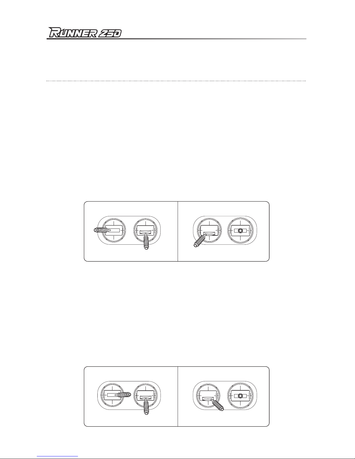
6.0 Prepare the Remote Controller
Open the battery cover and remove the battery box. According
to the battery positive and negative polarity, install 8pcs 5#
batteries or 8pcs NiMH batteries with same volume.
Warning:
Battery polarities must be correctly installed.
When insert the plug of battery box into power
socket of remote controller, the fool-proofing
port must be inserted into fool-proofing port.
Quick Start Guide


 user manual")