manuals.online logo
Brands
  1. Home
  2. •
  3. Brands
  4. •
  5. IFM Electronic
  6. •
  7. Switch
  8. •
  9. IFM Electronic efector100 IME User manual

IFM Electronic efector100 IME User manual

Bestimmungsgemäße Verwendung
Der Näherungsschalter erfaßt berührungslos
Metalle und meldet sie durch ein Schaltsignal.
Nennschaltabstand (Sn) siehe Typbezeichnung
auf dem Geräteaufkleber; Arbeitsbereich (Sa)
0 ... 0,81 x Sn; (Werte nach Norm-Messung auf
ST 37; bei anderen Metallen kürzer).
Montage
Befestigen Sie das Gerät sicher auf einer Mon-
tagehalterung. Sichern Sie es bei hoher mecha-
nischer Beanspruchung gegen Loslösen (siehe
Abb. 1).
Einbau nichtbündig.
• Freiräume an der aktiven Fläche bei Einbau
in Metall: Abb. 2 und 3.
• Mindestabstände bei Montage mehrerer
Schalter gleichen Typs: Abb. 4 und 5.
Function and features
This proximity switch detects metals without
contact and indicates their presence by provid-
ing a switched signal.
The nominal sensing range (Sn) can be seen in
the type designation on the type label on the
unit; operating distance (Sa) 0 ... 0,81 x Sn;
(values based on standard measurement with
mild steel; a shorter sensing range for other
metals).
Installation
Screw the proximity switch to a firm base. If
there is high mechanical stress, ensure that it
cannot work loose (fig. 1).
Non-flush installation
• Open space in front of the sensing face
when mounted in metal: fig. 2 and 3.
• Minimum distance when several switches of
the same type are mounted: fig. 4 and 5.
Fonctionnement et caractéristiques
Ce détecteur de proximité détecte les métaux
sans contact et indique leur présence par un
signal de commutation.
Pour la portée nominale (Sn) voir la désignati-
on sur l’étiquette, portée de travail (Sa)
0 ... 0,81 x Sn; (valeurs définies par mesure
selon les normes avec acier 37; en cas d’autres
métaux portée inférieure à Sn).
Montage
Visser le détecteur de proximité sur une base
de montage. En cas de sollicitation mécanique
importante, assurer que le détecteur de proxi-
mité ne se desserre pas; encastrable (fig. 1).
Montage non encastré
• Espaces libres devant la face active pour
montage sur bâti métallique: fig. 3.
• Distances minimales lorsque plusieurs détecteurs
de la même version sont montés: fig. 4 et 5.
Montageanleitung
Installation Instructions
Notice de Montage
Induktiver
Näherungsschalter IME
nichtbündig
Inductive
proximity switch IME
non flush
Détecteur de proximité
inductif IME
non encastrable
R
9mm
3 x Sna
2 x a 2 x a
8xS
n2xaa a
123
4 5
Sachnr. 701077/01 03/99 Technische Änderungen behalten wir uns ohne vorherige Ankündigung vor. Papier chlorfrei
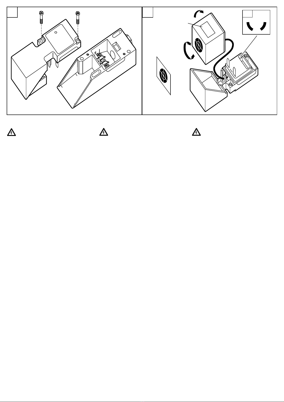
Aktive Fläche ausrichten
Nehmen Sie den Sensorwürfel ab (Abb. 7);
richten Sie die aktive Fläche aus und montieren
Sie den Sensorwürfel wieder.
Bei Montage des Geräts auf Metall muß die
Seite des Würfels, die mit dem Aufkleber (A)
markiert ist, zur Metallfläche zeigen.
Befestigen Sie den mitgelieferten Markierungs-
aufkleber nach Zusammenbau des Schalters
so, daß die aktive Fläche gekennzeichnet ist.
Betrieb
Prüfen Sie, ob der Schalter sicher funktioniert:
• Die LED leuchtet, wenn Versorgungsspan-
nung anliegt.
Der Betrieb des Näherungsschalters ist war-
tungsfrei. Für einwandfreies Funktionieren ist
zu beachten:
• Die aktive Fläche und der Freiraum sollten
von metallischen Ablagerungen und Fremd-
körpern freigehalten werden; insbesondere
bei Montage mit aktiver Fläche nach oben.
• EMV: Das Gerät erfüllt die Anforderungen
nach EN 60947-5-2.
Alignment of the sensing face
Remove the sensor cube (fig. 7); align sensing
face and re-insert the sensor cube.
When the proximity switch is mounted on a
metal surface, the face of the cube marked by
a sticker (A) must point to this metal surface.
When the switch has been screwed together,
position the marking sticker provided on the
outer surface of the switch unit so that the
sensing face is marked.
Operation
Check the safe functioning of the switch.
• The LED is lit when the supply voltage is
applied.
The operation of the proximity switch is main-
tenance free. For perfect functioning make
sure that:
• the sensing face and the open space are
kept free of metal deposits and foreign
bodies, particularly for installation with the
sensing face facing upwards.
• EMC: The unit conforms to the requirements
of EN 60947-5-2.
Orientation de la face active
Enlever le cube détecteur (fig. 7); orienter la
face active et remettre le cube détecteur.
En cas de montage du détecteur de proximité
sur und masse métallique la face du cube mar-
quée par un autocollant (A) doit s'orienter vers
la surface métallique.
Après avoir vissé le détecteur de proximité, pla-
cer l’autocollant livré sur la face extérieur du
bloc fonctionell de façon à marquer la face
active.
Fonctionnement
Vérifier le bon fonctionnement du détecteur.
• La LED est allumée lorsque la tension d’ali-
mentation est appliquée.
Pour un bon fonctionnement il faut respecter
les indications suivantes:
• La face active et l’espace libre doivent être
dégagés de toute présence de dépôts et de
corps étrangers métalliques, notamment en
cas de montage avec la face active vers le
haut.
• CEM: L’appareil est en harmonie avec les exi-
gences selon EN 60947-5-2.
Elektrischer Anschluß
Schalten Sie die Anlage vor dem
Anschluß spannungsfrei!
Öffnen Sie den Schalter (Abb. 6);
schließen Sie die Kabel nach den Anga-
ben auf dem Typenschild an.
Programmieren der Ausgangsfunktion:
Geräte, die nicht durch Anschluß program-
miert werden, werden als Schließer ausgelie-
fert. Zum Programmieren als Öffner öffnen Sie
die Drahtbrücke (Abb. 7A).
Electrical connection
Disconnect power before connecting the
proximity switch.
Open the switch (fig. 6); connect cable
in accordance with the instructions on
the type label.
Programming of the output function:
Units which are not programmed by means of
connections are provided in N.O. Open the
wire link for programming the N.C. function
(fig. 7A).
Raccordement électrique
Mettre l’installation hors tension avant le
raccordement du détecteur de proximité.
Ouvrir le détecteur de proximité (fig. 6);
raccorder le câble selon les instructions
de l’étiquette.
Programmation de la fonction de sortie:
Les appareils qui ne sont pas programmés par
leur raccordement sont livrés en fonction de
sortie travail. Ouvrir le pont pour les program-
mer en fonction de sortie repos (fig. 7A).
Aufkleber (B)
sticker (B)
autocollant (B)
7A
Aufkleber (A)
sticker (A)
autocollant (A)
6 7

Other IFM Electronic Switch manuals

IFM Electronic ZB0052 User manual

IFM Electronic

IFM Electronic ZB0052 User manual

IFM Electronic G Series User manual

IFM Electronic

IFM Electronic G Series User manual

IFM Electronic efector 150 User manual

IFM Electronic

IFM Electronic efector 150 User manual

IFM Electronic NAMUR KI-2015-N User manual

IFM Electronic

IFM Electronic NAMUR KI-2015-N User manual

IFM Electronic Efector 150 KNM User manual

IFM Electronic

IFM Electronic Efector 150 KNM User manual

IFM Electronic efector160 LI5 Series User manual

IFM Electronic

IFM Electronic efector160 LI5 Series User manual

IFM Electronic efector 150 KA User manual

IFM Electronic

IFM Electronic efector 150 KA User manual

IFM Electronic efector100 GG507S User manual

IFM Electronic

IFM Electronic efector100 GG507S User manual

IFM Electronic Efector 150 KG User manual

IFM Electronic

IFM Electronic Efector 150 KG User manual

IFM Electronic Efector 160 LI5045 User manual

IFM Electronic

IFM Electronic Efector 160 LI5045 User manual

IFM Electronic Efector110 User manual

IFM Electronic

IFM Electronic Efector110 User manual

IFM Electronic ecomat100 GI5002 User manual

IFM Electronic

IFM Electronic ecomat100 GI5002 User manual

IFM Electronic Efector 160 LI2 User manual

IFM Electronic

IFM Electronic Efector 160 LI2 User manual

IFM Electronic ZB0050 User manual

IFM Electronic

IFM Electronic ZB0050 User manual

IFM Electronic AL3100 User manual

IFM Electronic

IFM Electronic AL3100 User manual

Popular Switch manuals by other brands

Juniper QFX5120 Series Hardware guide

Juniper

Juniper QFX5120 Series Hardware guide

D-Link DGS-3130 Series Hardware installation guide

D-Link

D-Link DGS-3130 Series Hardware installation guide

Cisco Catalyst Express 520 introduction

Cisco

Cisco Catalyst Express 520 introduction

HP E3800-24G-2SFP+ Installation and getting started guide

HP

HP E3800-24G-2SFP+ Installation and getting started guide

Hama USB 2.0 4-Port-Hub user manual

Hama

Hama USB 2.0 4-Port-Hub user manual

MR COMTAP ARS operating instructions

MR

MR COMTAP ARS operating instructions

Ruijie RG-S6220-H Series Installation and Initialization

Ruijie

Ruijie RG-S6220-H Series Installation and Initialization

Smartwares SH4-99558 instruction manual

Smartwares

Smartwares SH4-99558 instruction manual

Ross Acuity Ultrix 5RU Installation and Cabling

Ross

Ross Acuity Ultrix 5RU Installation and Cabling

Minicom 1SU70017 quick start guide

Minicom

Minicom 1SU70017 quick start guide

H3C s5800 series troubleshooting guide

H3C

H3C s5800 series troubleshooting guide

Panasonic Magi'c Box user manual

Panasonic

Panasonic Magi'c Box user manual

Vector MZ3-V01 quick start guide

Vector

Vector MZ3-V01 quick start guide

ZyXEL Communications XGS1010-12 quick start guide

ZyXEL Communications

ZyXEL Communications XGS1010-12 quick start guide

Wise P953 manual

Wise

Wise P953 manual

Ecobee Switch+ user manual

Ecobee

Ecobee Switch+ user manual

ALFAtron SCK41TS user manual

ALFAtron

ALFAtron SCK41TS user manual

Keysight 34972A user guide

Keysight

Keysight 34972A user guide

manuals.online logo
manuals.online logoBrands
  • About & Mission
  • Contact us
  • Privacy Policy
  • Terms and Conditions

Copyright 2025 Manuals.Online. All Rights Reserved.