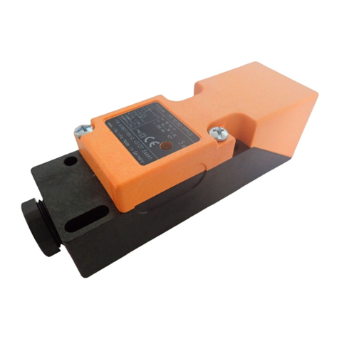
IFM Electronic Efector110 User manual

GM503S
Betriebsanleitung
Induktiver Sicherheitsschalter
Operating instructions
Fail-safe inductive switch
Notice d'utilisation
Détecteur de sécurité inductif
Instrucciones operativas
Detector inductivo de seguridad
Istruzioni per l'uso
Sensore di sicurezza induttivo
Bruksanvisning
Induktiv säkerhetsgivare
Sachnr. 701682/03 01/2006
DEUTSCH
ENGLISHFRANÇAIS
ESPAÑOL
ITALIANO
SVENSKA

Die Betriebsanleitung
... gilt für den induktiven Sicherheitsschalter GM503S.
... richtet sich an fachkundige Personen im Sinne von EMV-, der Nie-
derspannungs-Richtlinie und Sicherheitsvorschriften.
... ist Bestandteil des Gerätes. Sie enthält Angaben zum korrekten
Umgang mit dem Produkt. Lesen Sie sie vor dem Einsatz, damit Sie
mit Einsatzbedingungen, Installation und Betrieb vertraut werden.
Befolgen Sie die Sicherheitshinweise.
Inhalt
1. Sicherheitshinweise . . . . . . . . . . . . . . . . . . . . . . .Seite 3
2. Bestimmungsgemäße Verwendung . . . . . . . . . . . .Seite 4
3. Auflagen zur Projektierung
Produktunabhängige Auflagen . . . . . . . . . . . . . . .Seite 4
Produktabhängige Auflagen . . . . . . . . . . . . . . . . .Seite 4
4. Prüfungen/Zulassungen . . . . . . . . . . . . . . . . . . . .Seite 5
5. Lieferumfang . . . . . . . . . . . . . . . . . . . . . . . . . . .Seite 5
6. Montage . . . . . . . . . . . . . . . . . . . . . . . . . . . . . .Seite 6
7. Elektrischer Anschluß . . . . . . . . . . . . . . . . . . . . . .Seite 7
8. Aktive Fläche ausrichten . . . . . . . . . . . . . . . . . . .Seite 7
9. Fenstertechnik . . . . . . . . . . . . . . . . . . . . . . . . . . .Seite 8
10. Reaktionszeiten . . . . . . . . . . . . . . . . . . . . . . . . . .Seite 8
11. Sensorsignale . . . . . . . . . . . . . . . . . . . . . . . . . . .Seite 9
12. Technische Daten . . . . . . . . . . . . . . . . . . . . . . . .Seite 10
13. Maßzeichnung . . . . . . . . . . . . . . . . . . . . . . . . . .Seite 11
TÜV-Zertifikat . . . . . . . . . . . . . . . . . . . . . . . . . . . . . .Seite 62
Baumusterprüfbescheinigung . . . . . . . . . . . . . . . . . .Seite 63
EG-Konformitätserklärung . . . . . . . . . . . . . . . . . . . . .Seite 64
Notizen . . . . . . . . . . . . . . . . . . . . . . . . . . . . . . . . . .Seite 65
2

1. Sicherheitshinweise
Befolgen Sie die Angaben der Betriebsanleitung.
Nichtbeachten der Hinweise, Verwendung außerhalb der
nachstehend genannten bestimmungsgemäßen Verwendung,
falsche Installation oder Handhabung können Beeinträchti-
gungen der Sicherheit von Menschen und Anlagen zur Folge
haben.
Für Montage und bestimmungsmäßige Verwendung des Pro-
duktes sind die Hinweise in dieser Betriebsanleitung genau zu
beachten und ggf. die zutreffenden einschlägigen technischen
Normen im Rahmen der jeweiligen Anwendung zu berücksich-
tigen.
Bei Mißachtung von Hinweisen oder Normen, insbesondere
bei Eingriffen und/oder Veränderungen am Produkt, ist jede
Haftung ausgeschlossen.
Das Gerät darf nur von einer sicherheitstechnisch geschulten
Elektrofachkraft eingebaut, angeschlossen und in Betrieb ge-
setzt werden.
Nach der Installation des Systems muß eine komplette Funk-
tionsprüfung durchgeführt werden.
Schalten Sie das Gerät extern spannungsfrei bevor Sie irgend-
welche Arbeiten an ihm vornehmen. Schalten Sie ggf. auch
unabhängig versorgte Relais-Lastkreise ab.
Bei der Installation sind die Anforderungen der Norm EN60204
zu berücksichtigen.
Bei Fehlfunktion des Geräts setzen Sie sich bitte mit dem Her-
steller in Verbindung. Eingriffe in das Gerät können schwer-
wiegende Beeinträchtigungen der Sicherheit von Menschen
und Anlagen zur Folge haben. Sie sind nicht zulässig und
führen zu Haftungs- und Gewährleistungsauschluß.
3
DEUTSCH

2. Bestimmungsgemäße Verwendung
Der Sicherheitsschalter erfaßt berührungslos Metall.
Der sichere Zustand ist der stromlose Zustand (Endstufe abgeschaltet).
Der Sicherheitsschalter entspricht der Kategorie 3 gemäß EN954-1
bzw. AK 4 nach DIN V 19250 / DIN V 19251 bzw. DIN V VDE 0801
und PDF-S nach EN60947-5-3.
Hinweis zur Klassifizierung des Gerätes nach EN60947-5-2 bzw.
EN60947-5-3:
Abhängig von der Einbauart entspricht das Gerät der Klassifizierung
I1C40SP3S bzw. I2C40SP3S (siehe hierzu 6. Montage, Seite 6).
3. Auflagen zur Hardware-Projektierung
Der Einsatz des induktiven Sicherheitsschalters GM503S hat unter Be-
achtung folgender Auflagen zu erfolgen:
Produktunabhängige Auflagen
Die sicherheitstechnischen Anforderungen der jeweiligen Applikation
müssen mit den hier zugrundegelegten Anforderungen übereinstim-
men.
Die spezifizierten Einsatzbedingungen müssen eingehalten werden.
Bei allen extern an das System angeschlossenen Sicherheitsstrom-
kreisen ist das Ruhestromprinzip einzuhalten.
Durch administrative Maßnahmen in der Anwendung muß sicherge-
stellt werden, daß der montierte Sicherheitsschalter innerhalb einer
Zeitspanne von 24 h (intermittierender Betrieb) einem Selbsttest un-
terzogen wird. Dies wird erreicht durch
• Aus- und Einschalten der Versorgungsspannung (≥0,1 s)
• oder durch eine ausreichend lange Sensorentdämpfung (≥3 s)
• oder durch Abschaltung des Takteingangssignals (≥3 s).
Produktabhängige Auflagen
Bei Fehlern innerhalb des Sicherheitsschalters, die zum Übergang in
den als sicher definierten Zustand führen, sind Maßnahmen zu ergrei-
fen, die bei Weiterbetrieb der Gesamtsteuerung den sicheren Zustand
erhalten.
Beschädigte Geräte sind auszutauschen.
4

4. Prüfungen/Zulassungen
Der induktive Sicherheitsschalter GM503S
wurde vom TÜV zertifiziert.
Der Sicherheitsschalter wurde geprüft nach:
•98/37/EWG Europäische Maschinenrichtlinie
•73/23/EWG bzw. 93/68 Niederspannungsrichtlinie
•89/336/EWG EMV-Richtlinie bzw. 93/68/EWG
•DIN V VDE 0801:(1990) und Änderung A1: (1994) Grundsätze für
Rechner in Systemen mit Sicherheitsaufgaben
•DIN V 19250: (1994), AK 4, Grundlegende Sicherheitsbetrachtun-
gen für MSR-Schutzeinrichtungen
•DIN V 19251: (1995) MSR-Schutzeinrichtungen Anforderungen und
Maßnahmen zur gesicherten Funktion
•EN 954-1: (1997) Kategorie 3, Sicherheit von Maschinen, Sicher-
heitsbezogene Teile von Steuerungen
•EN 60204-1: (1997) (soweit anwendbar) Elektrische Ausrüstung von
Maschinen
•EN 60947-5-2: (1998) Niederspannungsschaltgeräte: Steuergeräte
und Schaltelemente - Näherungsschalter
•EN 60947-5-3: (1999) Niederspannungsschaltgeräte: Steuergeräte
und Schaltelemente - Anforderungen für Näherungsschalter mit de-
finiertem Verhalten unter Fehlerbedingungen
5. Lieferumfang
1 Sicherheitsschalter GM503S mit vormontiertem Montagewinkel,
1 Imbusschlüssel zur Fixierung des Sicherheitsschalters auf dem Mon-
tagewinkel,
1 Betriebsanleitung GM503S, Sachnr. 701682.
Sollte eines der genannten Bestandteile nicht vorhanden oder beschä-
digt sein, wenden Sie sich bitte an eine der rückseitigen ifm Nieder-
lassungen.
5
DEUTSCH

6. Montage
Befestigen Sie das Gerät mit dem Monta-
gewinkel. Sichern Sie es bei hoher me-
chanischer Beanspruchung gegen Loslö-
sen.
• In Kupfer, Aluminium und Messing ist
das Gerät bündig einbaubar gemäß
EN60947-5-2, Typ I1C40SP3.
• In Stahl ist das Gerät entspechend Typ
I2C40SP3 nach EN60947-5-2 einzubau-
en.
• Zusätzlich darf das Gerät einseitig bün-
dig auf Stahl eingebaut werden.
Einbaubedingungen gemäß Bilder 1 bis 3 sind zu beachten.
Da der induktive Sicherheitsschalter auf metallische Gegenstände rea-
giert, müssen entsprechende Maßnahmen getroffen werden, die ver-
hindern, daß metallische Gegenstände bewußt oder unbewußt auf
die aktive Fläche aufgebracht werden (siehe EN 1088, Verriegelungs-
einrichtungen in Verbindung mit trennenden Schutzeinrichtungen).
6
240
90 40
1 2 3

7. Elektrischer Anschluß
Das Gerät darf nur von einer Elektrofachkraft installiert werden.
Alle relevanten Normen (z.B. die Berechnung des Sicherheits-
abstandes zur Gefahrenstelle der Maschine) müssen beachtet
werden.
Schalten Sie die Anlage spannungsfrei. Schließen Sie das Gerät
nach den Angaben der Betriebsanleitung an.
8. Aktive Fläche ausrichten
Die Kabeldose ist drehbar
7
DEUTSCH
4 5 6
7 8 9
10 11 12

9. Fenstertechnik
Der Ausgang wird nur bei einer Bedämpfung zwischen 10 mm und
15 mm freigegeben (Zone 2, siehe 12. Technische Daten, Seite 10 ).
In den Zonen 1, 3 und 4 bleibt der Ausgang ausgeschaltet.
Der gesicherte Ausschaltabstand beträgt 30 mm.
Hinweis
Die Freigabezone ist für die beschriebenen Umgebungs- bzw. Ein-
satzbedingungen spezifiziert (siehe hierzu 12. Technische Daten, Sei-
te 10). Einsatzbedingungen außerhalb der angegebenen technischen
Daten ergeben eine andere Freigabezone.
10. Reaktionszeiten
(Entfernen aus der Freigabezone)
8
10 15 30
1234
0mm
Sicherheitsschalter Bedämpfungselement
Freigabe-
zone
Zonenwechsel Reaktionsszeit (max.)
von nach
2 3 80 ms
2 1 360 ms
2 4 20 ms

11. Sensorsignale
Der Sicherheitsschalter ist mit einem Taktsignal an seinem Taktein-
gang zu betreiben. Das Takteingangssignal (TE) muß die vorgegebe-
nen Zeitbedingungen erfüllen.
Ist das Bedämpfungselement in Zone 2 und liegt kein Sensorfehler
vor, wird das Takteingangssignal an den Ausgang invertiert weiterge-
reicht.
Die Verzögerungszeit td [Takteingang (TE) →Ausgang] ist ≤1ms
(typ. 220 µs).
Der Ausgang wird ausgeschaltet, wenn das Takteingangssignal (TE)
"high" ist.
Wird während dieser Zeit ein Fehler oder eine Entfernung aus der
Zone 2 festgestellt, bleibt danach der Ausgang ausgeschaltet.
Eine Abweichung vom Zeitschema am Ausgang stellt einen Fehler
dar.
Wenn sich das Bedämpfungselement in der Zone 2 befindet, beträgt
die Bereitschaftsverzögerungszeit max. 1,3 s + T.
Die Freigabe erfolgt mit einer fallenden Flanke am Takteingang.
Die Fehlererkennungszeit des Schalters beträgt bei sicherheitsrelevan-
ten Fehlern eine Periodendauer; mindestens jedoch 360 ms.
Querschlüsse müssen von der angeschlossenen SPS oder Auswerte-
einheit erkannt werden.
9
DEUTSCH
Takteingang (TE) 0
1
0
1
T1 T2
td
T
Ausgang
T1 ≥120 ms
T2 ≥120 ms
T = 240...500 ms
td ≤1 ms (typ. 220 µs)

12. Technische Daten
Best.-Nr.: GM503S
Typ: GIMC-4030-US
Wenn nicht anders angegeben, beziehen sich alle Daten im gesam-
ten Temperaturbereich auf Referenzmeßplatte nach EN60947-5-2
(FE360 = St37) 45x45x1 mm.
Elektrische Ausführung: DC
Betriebsspannung: 18...30 V (inkl. 5% Restwelligkeit)
Stromaufnahme: < 15 mA
Kurzschlußschutz: ja
Freigabezone: 10...15 mm
Gesicherter Ausschaltabstand: 30 mm
Schaltfrequenz: min. 0,2 Hz
Spannungsabfall: < 2,5 V
Schaltzustandsanzeige: —
Betriebsart: intermittierender Betrieb
Umgebungstemperatur: -25...70°C
Relative Feuchte: < 95%
Höhe über NN: max. 2000 m
Schutzart: IP67
Gehäusewerkstoffe: PPE, Zinkdruckguß
Anschluß: M12 Steckverbindung, Goldkontakte
10
L+
2
1
TE OUT
+24V
G1500x
oder
SPS
4A IN
3L GND
(BN)
(WH)
(BK)
(BU)
4
21
3
Ansicht auf die
Stiftseite

13. Maßzeichnung
11
DEUTSCH
40
M12 x1
40
66
17
34
46
61
30
20
5,4
10
5,4
6
Hinweis:
Adernfarbe gilt für die Verwendung von ifm Kabeldosen.
BK = schwarz
BN = braun
BU = blau
WH = weiß

The operating instructions
... apply to the fail-safe inductive switch GM503S.
... are intended for authorised persons according to the EMC, low
voltage directives and safety instructions.
... are part of the unit. They contain information about the correct
handling of the product. Read them before use to familiarise yourself
with operating conditions, mounting and operation. Follow the safe-
ty instructions.
Contents
1. Safety instructions . . . . . . . . . . . . . . . . . . . . . . .page 13
2. Function and features . . . . . . . . . . . . . . . . . . . . .page 14
3. Configuration requirements
Product-independent requirements . . . . . . . . . . .page 14
Product-dependent requirements . . . . . . . . . . . . .page 14
4. Tests/approvals . . . . . . . . . . . . . . . . . . . . . . . . . .page 15
5. Items supplied . . . . . . . . . . . . . . . . . . . . . . . . . .page 15
6. Installation . . . . . . . . . . . . . . . . . . . . . . . . . . . . .page 16
7. Electrical connection . . . . . . . . . . . . . . . . . . . . . .page 17
8. Align the active face . . . . . . . . . . . . . . . . . . . . . .page 17
9. Window technology . . . . . . . . . . . . . . . . . . . . . .page 18
10. Response times . . . . . . . . . . . . . . . . . . . . . . . . . .page 18
11. Sensor signals . . . . . . . . . . . . . . . . . . . . . . . . . . .page 19
12. Technical data . . . . . . . . . . . . . . . . . . . . . . . . . . .page 20
13. Scale drawing . . . . . . . . . . . . . . . . . . . . . . . . . . .page 21
TÜV certificate . . . . . . . . . . . . . . . . . . . . . . . . . . . . .page 62
Type test certificate . . . . . . . . . . . . . . . . . . . . . . . . . .page 63
EC Declaration of Conformity . . . . . . . . . . . . . . . . . .page 64
Notes . . . . . . . . . . . . . . . . . . . . . . . . . . . . . . . . . . .page 65
12

1. Safety instructions
Follow the operating instructions.
Non-observance of the instructions, operation which is not in
accordance with use as prescribed below, incorrect installation
or handling can affect the safety of people and equipment.
For mounting and prescribed use of the product the notes in
the operating instructions must be carefully observed and the
applicable technical standards relevant for the application
have to be considered.
In case of non-observance of notes or standards, specially
when tampering with and/or modifying the product any
liability is excluded.
The unit must be installed, connected and put into operation
by a qualified electrician trained in safety technology.
After installation of the system a complete function check
must be carried out.
Disconnect the device externally before handling it. Also
disconnect any independently supplied relay load circuits.
For installation the requirements according to EN 60204 must
be observed.
In case of malfunction of the unit please contact the
manufacturer. Tampering with the device can seriously affect
the safety of people and equipment. This is not permitted and
leads to an exclusion of liability and warranty.
13
ENGLISH

2. Function and features
The fail-safe switch detects metals without contact.
The safe state is the no-current state (output stage switched off).
The fail-safe switch corresponds to category 3 to EN 954-1 or require-
ment class 4 to DIN V 19250 / DIN V 19251 or DIN V VDE 0801 and
PDF-S to EN 60947-5-3.
Information on the classification of the unit to EN 60947-5-2 or EN
60947-5-3: Depending on the type of mounting the unit corresponds
to classification I1C40SP3S or I2C40SP3S (please also see 6. Installa-
tion, page 16).
3. Requirements for the hardware configuration
For using the fail-safe inductive switch GM503S the following must be
taken into account:
Product-independent requirements
The safety requirements of the respective application must corre-
spond to the requirements stated in these instructions.
The specified operating conditions must be complied with.
The principle of normally closed operation must be applied to all ex-
ternal safety circuits connected to the system.
By taking appropriate measures in the application it must be ensured
that the mounted fail-safe switch is subjected to a self-test within a
period of 24 hours (intermittent operation).
This is achieved by
• switching off and on the supply voltage (≥0.1 s)
• or by undamping the sensor for a sufficiently long time (≥3 s)
• or by deactivating the clock input signal (≥3 s).
Product-dependent requirements
In case of faults within the fail-safe switch which result in the defined
safe state, measures have to be taken which maintain the safe state
when the complete control system continues to be operated.
Damaged units are to be exchanged.
14

4. Tests/approvals
The fail-safe inductive switch GM503S has
been certified by TÜV.
The fail-safe switch was tested in accordance with:
•98/37/EEC European machinery directive
•73/23/EEC or 93/68 Low voltage directive
•89/336/EEC EMC directive or 93/68/EEC
•DIN V VDE 0801: (1990) and amendment A1: (1994) Principles for
computers in safety-related systems
•DIN V 19250: (1994), Requirement class AK 4, Fundamental safety
aspects to be considered for measurement and control equipment
•DIN V 19251: (1995) MC protection equipment - Requirements and
measures for safeguarded function
•EN 954-1: (1997) Category 3, Safety of machinery. Safety-related
parts of control systems
•EN 60204-1: (1997) (where applicable) Electrical equipment of ma-
chines
•EN 60947-5-2: (1998) Low-voltage switchgear and controlgear -
Control and switchgear - proximity switches
•EN 60947-5-3: (1999) Low-voltage switchgear and controlgear -
Control circuit devices and switching elements - Requirements for
proximity devices with defined behaviour under fault conditions
5. Items supplied
1 fail-safe switch GM503S with premounted angle bracket,
1 Allen key for fixing the fail-safe switch onto the angle bracket,
1 x operating instructions GM503S, ident no. 701682.
If one of the above-mentioned components is missing or damaged,
please contact one of the ifm branch offices overleaf.
15
ENGLISH

6. Installation
Fix the unit with the angle bracket. In
case of high mechanical stress secure it so
that it does not come loose.
• The unit can be mounted flush with
copper, aluminium and brass according
to EN 60947-5-2, type I1C40SP3.
• The unit is to be mounted in steel ac-
cording to type I2C40SP3 to EN 60947-
5-2.
• In addition one side of the unit can be
mounted flush with steel.
The mounting conditions according to figures 1 to 3 are to be taken
into account.
Since the fail-safe inductive switch reacts to metallic objects, corre-
sponding measures must be taken to avoid metallic objects being
placed on the sensing face intentionally or unintentionally (see EN
1088, Interlocking devices associated with guards).
16
240
90 40
1 2 3

7. Electrical connection
The unit must only be connected by a skilled electrician.
All relevant standards (e.g. calculation of the safety distance to
the danger area of the machine) must be complied with.
Disconnect the installation from power. Connect the unit ac-
cording to the indications in the operating instructions.
8. Align the sensing face
The socket is rotatable
17
ENGLISH
4 5 6
7 8 9
10 11 12

9. Window technology
The output is only enabled in case of a damping between 10 mm
and 15 mm (zone 2, see 12. Technical data, page 20).
In the zones 1, 3 and 4 the output remains switched off.
The safe switching off distance is 30 mm.
Note
The enable zone is specified for the described environmental condi-
tions or conditions of use (please see 12. Technical data, page 20).
Conditions of use outside the given technical data result in a differ-
ent enable zone.
10. Response times
(removal from the enable zone)
18
10 15 30
1234
0mm
fail-safe switch damping element
enable
zone
Change of zones Response time (max.)
from to
2 3 80 ms
2 1 360 ms
2 4 20 ms

11. Sensor signals
The fail-safe switch has to be operated with a clock signal on its clock
input. The clock input signal (TE) must meet the defined time condi-
tions.
If the damping element is in zone 2 and there is no sensor fault, the
clock input signal is inverted and transferred to the output.
The delay time td [clock input (TE) →output] is ≤1 ms (typ. 220 µs).
The output is switched off if the clock input signal (TE) is "high".
If during this time a fault or removal from zone 2 occurs, the output
remains switched off.
A deviation from the time diagram at the output represents a fault.
If the damping element is in zone 2, the power-on delay time is max.
1.3 s + T.
Enabling takes place with a falling edge at the clock input.
In case of safety-related faults the fault detection time of the switch is
the duration of one period, but at least 360 ms.
Cross-bridging must be detected by the connected PLC or evaluation
unit.
19
ENGLISH
Takteingang (TE) 0
1
0
1
T1 T2
td
T
Ausgang
T1 ≥120 ms
T2 ≥120 ms
T = 240...500 ms
td ≤1 ms (typ. 220 µs)
Clock input (TE)
Output

12. Technical data
Order no.: GM503S
Type: GIMC-4030-US
If not otherwise stated, all data in the complete temperature range
refer to the reference target to EN 60947-5-2 (FE 360 = steel) 45 x
45 x 1 mm.
Electrical design: DC
Operating voltage: 18...30 V (incl. 5% residual ripple)
Current consumption: < 15 mA
Short-circuit protection: yes
Enable zone: 10...15 mm
Safe switching off distance: 30 mm
Switching frequency: min. 0.2 Hz
Voltage drop: < 2.5 V
Switching status indication: —
Operating mode: intermittent operation
Operating temperature: -25...70°C
Relative humidity: < 95%
Height above sea level: max. 2000 m
Protection: IP67
Housing materials: PPE, diecast zinc
Connection: M12 connector, gold-plated contacts
20
L+
2
1
TE OUT
+24V
G1500x
oder
SPS
4A IN
3L GND
(BN)
(WH)
(BK)
(BU)
4
21
3
View on pin side
G1500x
or
plc
Other manuals for Efector110
1
This manual suits for next models
2
Table of contents
Languages:
Other IFM Electronic Switch manuals

IFM Electronic
IFM Electronic Efector 160 LI2 User manual

IFM Electronic
IFM Electronic Efector 150 KG User manual

IFM Electronic
IFM Electronic efector100 IME User manual

IFM Electronic
IFM Electronic efector100 GG507S User manual

IFM Electronic
IFM Electronic ZB0050 User manual

IFM Electronic
IFM Electronic G Series User manual

IFM Electronic
IFM Electronic efector160 LI5 Series User manual

IFM Electronic
IFM Electronic efector 150 KA User manual

IFM Electronic
IFM Electronic efector 150 User manual

IFM Electronic
IFM Electronic Efector 150 KNM User manual