IFM Electronic Efector 160 LI5045 User manual

Bedienungsanleitung
Operating instructions
Notice utilisateurs
Kapazitiver
Niveauschalter
Capacitive level switch
Détecteur de niveau
capacitif
LI5045
R
Sachnr. 701927/00 02/05
DEUTSCHENGLISHFRANÇAIS

2
Inhalt
1. Bestimmungsgemäße Verwendung . . . . . . . . . . . . . . Seite 4
2. Montage . . . . . . . . . . . . . . . . . . . . . . . . . . . . . . . . . Seite 5
3. Elektrischer Anschluß . . . . . . . . . . . . . . . . . . . . . . . . Seite 6
4. Inbetriebnahme / Betrieb . . . . . . . . . . . . . . . . . . . . . Seite 7
5. Technische Daten . . . . . . . . . . . . . . . . . . . . . . . . . . . Seite 8
Contents
1. Function and features . . . . . . . . . . . . . . . . . . . . . . . page 9
2. Installation . . . . . . . . . . . . . . . . . . . . . . . . . . . . . . . page 10
3. Electrical connection . . . . . . . . . . . . . . . . . . . . . . . page 11
4. Installation and set-up / operation . . . . . . . . . page 12
5. Technical data . . . . . . . . . . . . . . . . . . . . . . . . . . . . page 13
Contenu
1. Fonctionnement et caractéristiques . . . . . . . . . . . . . page 14
2. Montage . . . . . . . . . . . . . . . . . . . . . . . . . . . . . . . . page 15
3. Raccordement électrique . . . . . . . . . . . . . . . . . . . . page 16
4. Mise en service / Fonctionnement . . . . . . . . . . . . . . page 17
5. Données techniques . . . . . . . . . . . . . . . . . . . . . . . . page 18

3
Maßzeichnung
Scale drawing
Dimensions
L
16
54
M12 x1
21,3
1
2
3
L=273mm
* im Auslieferungszustand elektronisch verriegelt
on delivery electronically locked
au moment de livraison verrouilléélectroniquement
1
2
3
Programmiertaste* Programming button* Bouton-poussoir*
LEDs (grün, gelb, rot) LED’s
(green, yellow, red)
LEDs
(verte, jaune, rouge)
Aktive Zone (25mm)
mit radialer Erfassungs-
charakteristik
active zone (25mm)
with radial detection
characteristics
zone active (25mm)
avec une
caractéristique de
détection radiale

1. Bestimmungsgemäße Verwendung
Einsatzbereich
Dieses Gerät wurde speziell für die Bedürfnisse des
Werkzeugmaschinenbaus konzipiert. Es ist insbesondere geeignet für
die Überwachung von Kühlschmieremulsionen, aber auch anderen
wasserbasierten Medien. Das Gerät ist weitgehend immun gegen
Anhaftungen fast aller Art auf dem Sondenstab (z.B. Metallpartikel,
Schaum).
Das Gerät ist nicht geeignet für Öle, Granulate und Schüttgüter,
Säuren und Laugen; es ist nicht geeignet für den Lebensmittel- und
Galvanikbereich.
Stellen Sie im Zweifelsfall die ordnungsgemäße Funktion durch einen
Applikationstest sicher.
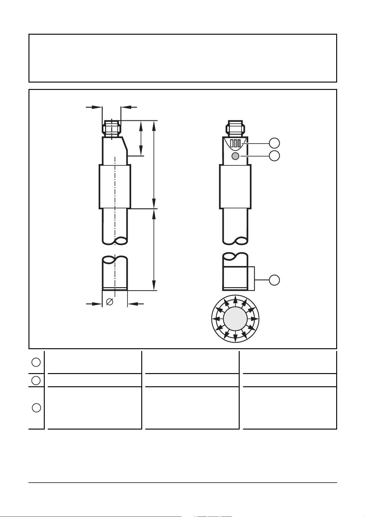
Funktionsbeschreibung
•Das Gerät erfaßt in direktem Kontakt mit dem Medium, ob eine
gewünschte Füllhöhe erreicht ist und meldet dies durch ein
Schaltsignal (Schließer oder Öffner, programmierbar durch
Anschlußbelegung; →Seite 6).
•Die Füllhöhe wird festgelegt durch die Einbaulänge (→Seite 5,
Montage).
•Das Gerät ist werksseitig voreingestellt und bei ordnungsgemäßer
Verwendung sofort betriebsbereit. Die Programmiertaste ist im
Auslieferungszustand elektronisch verriegelt. Programmierung oder
Abgleich sind nicht erforderlich!
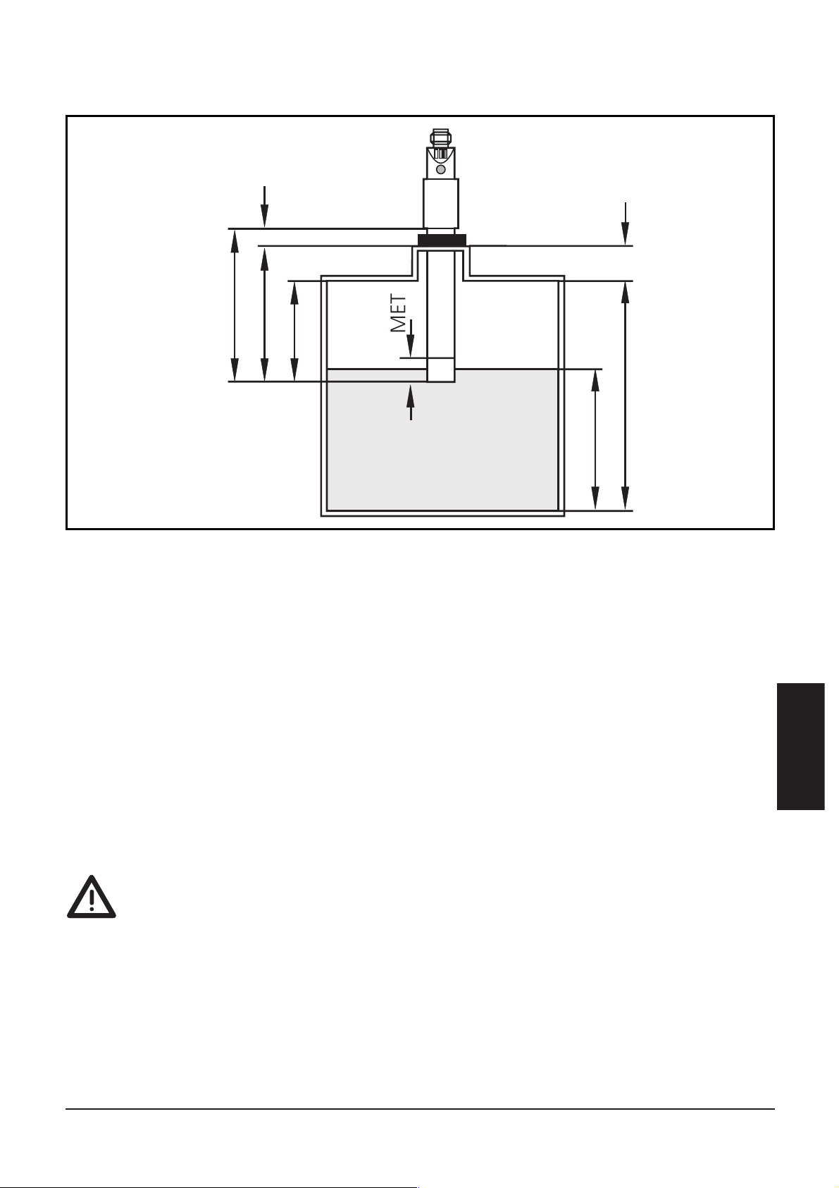
•Einbau: senkrecht von oben.
Das Gerät arbeitet mit radialer Erfassungs-Charakteristik.
Dadurch wird bei senkrechtem Einbau die Erfassung von Medien
unterhalb der Aktiven Zone unterdrückt. Medien werden erst dann
erfaßt, wenn die Aktive Zone bedeckt ist.
4
Schließer
Öffner
Füllhöhe erreicht Füllhöhe nicht erreicht
Ausgang = EIN Ausgang = AUS
Ausgang = AUS Ausgang = EIN

2. Montage
Montieren Sie das Gerät senkrecht von oben in den Behälter.
Montagelänge (L3): mindestens 60mm.
Verwenden Sie für sichere und einfache Montage das ifm-
Montagezubehör (Bestell-Nr. E43000 - E43007).
Maximaler Behälterdruck bei Einbau mit ifm-Montagezubehör:
0,5bar.
•Das Gerät sollte in metallischen Behältern verwendet werden.
Die Verwendung in Kunststoffbehältern wird nicht empfohlen.
Hierbei kann es zu Funktionsstörungen kommen, da der elektrische
Kontakt des Mediums zur Anlagenmasse möglicherweise unzurei-
chend ist.
5
DEUTSCH
MET
L3
A
H
L1
L
L2
SH
A = Ansprechhöhe
H = Behälterhöhe
SH = Stutzenhöhe
L = Stablänge (Sondenstab)
L1 = Einbaulänge
L2 = Auszugslänge
L3 = Montagelänge
MET = maximale Eintauchtiefe (= Aktive Zone; 25mm)

•Der Abstand zwischen Aktiver Zone und metallischer
Behälterwand/ Behälterboden mußmindestens 20mm betragen.
•Werden mehrere Geräte LI5 in einen Behälter eingebaut, sollte
ein Mindestabstände von 40mm (von Stabmitte zu Stabmitte) zwi-
schen ihnen eingehalten werden.
•Abstand zwischen LI5xxx- und LKxxxx-Geräten: min. 60mm von
Stabmitte zu Stabmitte.
3. Elektrischer Anschluß
Das Gerät darf nur von einer Elektrofachkraft installiert werden.
Befolgen Sie die nationalen und internationalen Vorschriften zur
Errichtung elektrotechnischer Anlagen.
Schalten Sie die Anlage spannungsfrei und schließen Sie das Gerät fol-
gendermaßen an ( = Schließer / = Öffner):
6
L+
L
BN
BK
BU
L+
L
BU
BK
BN
1
4
3
3
4
1
3
1
4
2
Adernfarben bei ifm-Kabeldosen:
1 = BN (braun), 3 = BU (blau), 4 = BK (schwarz).

4. Inbetriebnahme / Betrieb
Prüfen Sie nach Einbau und Anschluß, ob das Gerät sicher funktio-
niert.
Entleeren und füllen Sie den Behälter und prüfen Sie dabei, ob das
Gerät richtig schaltet und ob die Vorgänge durch die LEDs richtig
angezeigt werden.
LED-Anzeigen / Störanzeigen während des Betriebs:
Funktionskontrolle
Die rote LED zeigt nicht eine Gerätestörung an. Sie signalisiert, daß
sich das interne Sensorsignal in der Nähe der Schaltschwelle befindet.
Dabei sind 2 Fälle zu unterscheiden:
•Normaler Betrieb / Sicheres Funktionieren
Die rote LED leuchtet vorübergehend auf, wenn sich der
Füllstand der Ansprechhöhe nähert oder wenn er unter die
Ansprechhöhe fällt.
•Warnung vor möglicher Fehlfunktion
Leuchtet die rote LED konstant, sind die Arbeitsbedingungen
nicht mehr optimal.
Z. B. kann sich durch Schmutzablagerungen auf dem Sondenstab
das Schaltniveau innerhalb der Aktiven Zone geändert haben.
Sie können Gegenmaßnahmen erfgreifen, bevor es zu einer
Fehlfunktion in der Anlage kommt. Überprüfen Sie z.B. die
Einbauhöhe oder reinigen Sie das Gerät.
7
DEUTSCH
LED grün leuchtet Gerät ist im Betriebsmodus
LED gelb leuchtet Ausgang ist durchgeschaltet
LEDs gelb und
rot blinken schnell (ca. 2Hz) Kurzschlußim Schaltausgang
LED rot leuchtet Funktionskontrolle
LED rot blinkt schnell (ca. 2Hz) Interner Fehler oder Beschädigung des
Geräts

5. Technische Daten
8
Betriebsspannung [V] . . . . . . . . . . . . . . . . . . . . . . . . . . . . . . . 10 ... 36 DC
Strombelastbarkeit [mA] . . . . . . . . . . . . . . . . . . . . . . . . . . . . . . . . . . . 250;
Kurzschlußschutz, getaktet;
verpolungssicher / überlastfest
Spannungsabfall [V] . . . . . . . . . . . . . . . . . . . . . . . . . . . . . . . . . . . . . < 2,5
Stromaufnahme [mA] . . . . . . . . . . . . . . . . . . . . . . . . . . . . . < 13 (24V DC)
Schaltfrequenz [Hz] . . . . . . . . . . . . . . . . . . . . . . . . . . . . . . . . . . . . . . . . . 5
Max. Behälterdruck [bar]. . . . . . . . . . . . . . . . . . . . . . . . . . . . . . . . . . . . 0,5
(bei Einbau mit ifm-Montagezubehör)
Gehäusewerkstoffe . . . . . . . . . . . . . . . . . . . . . . . . PP (Polypropylen); TPE/V
Werkstoffe in Kontakt mit dem Medium . . . . . . . . . . . . . PP (Polypropylen)
Umgebungstemperatur [°C] . . . . . . . . . . . . . . . . . . . . . . . . . . . . . 0 ... +80
Mediumtemperatur [°C] . . . . . . . . . . . . . . . . . . . . . . . . . . . . . . . 0 ... +35
Schutzart, Schutzklasse . . . . . . . . . . . . . . . . . . . . . . . . . . . . . . . . . IP 67, II
EMV
IEC 1000-4-2 / EN 61000-4-2: . 15kV Luftentladung / 8kV Kontaktentladung
IEC 1000-4-3 / EN 61000-4-3: . . . . . . . . . . . . . . . . 10V/m, 80 ... 1000MHz
IEC 1000-4-4 / EN 61000-4-4: . . . . . . . . . . . . . . . . . . . . 2kV Koppelzange
IEC 1000-4-6 / EN 61000-4-6: . . . . . . . . . . . . . . . . . . 10V, 0,15 ... 80MHz
IEC 255-5: . . . . . . . . . . . . . . . . . . . . . . . . . . . . . . . . . . . . . . . . . . . . . 1kV

1. Function and features
Applications:
The unit was specially designed to meet the requirements of machine
tool building. It is specially suitable for monitoring coolant emulsions
as well as other hydrous media.
The unit is virtually immune to build-up of almost any kind on the
probe (e.g. particles of metal, foam).
The sensor is not suitable for oils, granulates and bulk materials, acids
and alkalis. It is not suitable for food and electroplating applications.
In case of doubt ensure the correct function by performing a test in
your application.
Description of the function
The sensor detects the level of media in tanks.
•The unit detects by direct contact with the medium whether the
requested level is reached and indicates this by a switched signal
(N.O. or N.C., programmmable by wiring; →page 11).
•The level is determined by the installation length (→page 10,
Installation).
•The unit is preset at the factory and is immediately ready for ope-
ration if used correctly. On delivery the programming button is elec-
tronically locked. Programming or adjustment are not necessary!
•Installation: vertical from the top.
The unit operates with radial detection characteristics. Therefore
media below the active zone are not detected in the case of verti-
cal installation. Media are only detected when the active zone is
covered.
9
ENGLISH
N.O.
N.C.
level reached level not reached
output = ON output = OFF
output = OFF output = ON

2. Installation
Mount the unit vertical from the top.
Mounting length (L3): minimum 60mm.
For safe and easy mounting use the ifm mounting accessories (Order
no. E43000 - E43007).
Maximum vessel pressure when mounted with mounting acces-
sories: 0.5bar.
•The units should be used in metal tanks.
Use in plastic tanks is not recommended. When the unit is used in
plastic tanks, malfunctions may occur because the electrical contact
of the medium to the machine ground may be insufficient.
10
MET
L3
A
H
L1
L
L2
SH
A = response level
H = height of the tank
SH = height of the neck
L = probe length (probe)
L1 = installation length
L2 = outside length
L3 = mounting length
MET = maximum immersion depth (= active zone, 25mm)

•The distance between the active zone and the wall/bottom of the
metal tank must be min. 20mm.
•When several LI5 units are mounted in one tank minimum
distances between them must be maintained: 40mm from the cen-
treline of a probe to the centreline of another probe.
•Distance between sensors type LI5xxx and LKxxxx: min. 60mm from
the centreline of a probe to the centreline of another probe.
3. Electrical connection
The unit must only be connected by an electrician.
The national and international regulations for the installation of
electrical equipment must be observed.
Disconnect power before connecting the unit,
( = N.O. / = N.C.):
11
ENGLISH
L+
L
BN
BK
BU
L+
L
BU
BK
BN
1
4
3
3
4
1
3
1
4
2
Core colours of ifm sockets:
1 = BN (brown), 3 = BU (blue), 4 = BK (black).

4. Installation and set-up / operation
After mounting and wiring check whether the unit operates correctly.
Empty and fill the tank and check whether the unit switches correctly
and whether the LED's correctly indicate the operations.
Display by LEDs:
Function check
The red LED indicates no malfunction of the unit, it indicates that the
internal sensor signal is near the switching threshold.
2 cases can be distinguished:
•Normal operation/safe operation
The red LED is lit temporarily when the level of the medium
approaches the response level or falls below the response level.
•Warning of possible malfunction
If the red LED is lit continuously, the operating conditions are no
longer optimum.
It is for example possible that build-up of dirt on the probe has
changed the switching level within the active zone.
You can take preventive measures to avoid a malfunction. Check
for example the installation height or clean the unit.
12
LED green lights unit is ready for operation
LED yellow lights the output has switched
LED’s yellow and
red flash quickly (2Hz) short circuit of the switching output
LED red lights function check
LED red flashes quickly (2Hz) internal fault or unit damaged

5. Technical data
13
ENGLISH
Operating voltage [V] . . . . . . . . . . . . . . . . . . . . . . . . . . . . . . . 10 ... 36 DC
Current rating [mA] . . . . . . . . . . . . . . . . . . . . . . . . . . . . . . . . . . . . . . 250;
Short-circuit protection;
Reverse polarity protection / Overload protection
Voltage drop [V] < 2.5
Current consumption [mA] . . . . . . . . . . . . . . . . . . . . . . . . . < 13 (24V DC)
Switching frequency [Hz] . . . . . . . . . . . . . . . . . . . . . . . . . . . . . . . . . . . . . 5
Maximum vessel pressure [bar] . . . . . . . . . . . . . . . . . . . . . . . . . . . . . . . 0.5
. . . . . . . . . . . . . . . . . . . . . . . .(when mounted with mounting accessories)
Housing material . . . . . . . . . . . . . . . . . . . . . . . . . PP (polypropylene); TPE/V
Materials (wetted parts) . . . . . . . . . . . . . . . . . . . . . . . . . PP (polypropylene)
Operating temperature [°C] . . . . . . . . . . . . . . . . . . . . . . . . . . . . . 0 ... +80
Medium temperature [°C] . . . . . . . . . . . . . . . . . . . . . . . . . . . . . . 0 ... +35
Protection . . . . . . . . . . . . . . . . . . . . . . . . . . . . . . . . . . . . . . . . . . . IP 67, II
EMC
IEC 1000-4-2 / EN 61000-4-2: . . 15kV air discharge / 8kV contact discharge
IEC 1000-4-3 / EN 61000-4-3: . . . . . . . . . . . . . . . . 10V/m, 80 ... 1000MHz
IEC 1000-4-4 / EN 61000-4-4: . . . . . . . . . . . . . . . . . . . 2kV coupling pliers
IEC 1000-4-6 / EN 61000-4-6: . . . . . . . . . . . . . . . . . . 10V, 0.15 ... 80MHz
IEC 255-5: . . . . . . . . . . . . . . . . . . . . . . . . . . . . . . . . . . . . . . . . . . . . . 1kV

1. Fonctionnement et caractéristiques
Applications :
Le détecteur de niveau a étéconçu notamment pour satisfaire aux
exigences des applications en machines-outils. L'appareil est particu-
lièrement appropriépour contrôler des liquides d'arrosage et de lubri-
fication ainsi que d'autres fluides aqueux. L'appareil est résistant à
presque toute forme de dépôt sur la sonde (par ex. particules métal-
liques, mousse).
Le détecteur n'est pas appropriépour des huiles, des fluides pulvéru-
lents et matières en vrac, des acides et alcalis. Il n'est pas approprié
pour des applications agroalimentaires et de galvanisation.
En cas de doute, s'assurer du bon fonctionnement en effectuant un
test dans l'application.
Description de la fonction
Le détecteur détecte le niveau de fluides dans des cuves.
•Il détecte en contact direct avec le fluide si le niveau souhaitéest
atteint et l'indique par un signal de commutation (programmation
N.O. / normalement ouvert ou normalement fermé/ N.F., suivant le
branchement de l'alimentation, →page 16).
•Le niveau àdétecter est déterminépar la longueur d'installation
(→page 15, Montage).
•L'appareil est réglépar défaut et immédiatement opérationnel si
utilisécorrectement. Au moment de livraison, le bouton de pro-
grammation est verrouilléélectroniquement. Programmation ou
ajustage ne sont pas nécessaires !
•Installation : vertical par le haut.
La zone de détection du détecteur est radiale ce qui signifie que
des fluides qui se situent en-dessous de la zone active ne sont pas
détectés en cas d'installation verticale. Les fluides ne sont
détectés que si la zone active est couverte.
14
N.O.
N.C.
niveau atteint niveau pas atteint
sortie = commutée sortie = non commutée
sortie = non commutée sortie = commutée

2. Montage
Monter l'appareil verticalement par le haut dans la cuve.
Longueur de montage (L3) : min. 60mm.
Utiliser un accessoire de montage ifm (No de command. E43000 -
E43007) pour un montage sûr et facile.
Pression max. du récipient si montéavec les accessoires de
montage : 0,5bar.
•L'appareil doit être utilisédans des cuves métalliques.
L'emploi dans des cuves plastiques n'est pas recommandé. En cas
d'emploi dans des cuves plastiques, des défauts de fonctionnement
peuvent se produire àcause d'un contact électrique insuffisant du
fluide àla terre de la machine.
15
FRANÇAIS
MET
L3
A
H
L1
L
L2
SH
A = niveau de réponse
H = hauteur de la cuve
SH = hauteur du collet
L = longueur de la sonde
L1 = longueur d'installation
L2 = longueur extérieure
L3 = longueur de montage
MET = profondeur d'immersion maximale (= zone active 25mm)

•La distance entre la zone active et la paroi / le fond de la cuve métal-
lique doit être au minimum de 20mm.
•Si plusieurs appareils LI5 sont montés dans une cuve, des distances
minimales doivent être respectées entre eux : 40mm de l'entraxe
d'une sonde àl'entraxe d'une autre sonde.
•Distance entre détecteurs type LI5xxx et LKxxxx : min. 60mm de
l'entraxe d'une sonde àl'entraxe d'une autre sonde.
3. Raccordement électrique
L'appareil doit être montépar un électricien.
Les règlements nationaux et internationaux relatifs àl'installa-
tion de matériel électrique doivent être respectés.
Mettre l’installation hors tension avant le raccordement.
Schéma de branchement : ( = N.O. / = N.F.) :
16
L+
L
BN
BK
BU
L+
L
BU
BK
BN
1
4
3
3
4
1
3
1
4
2
Couleurs des fils conducteurs des connecteurs femelles ifm:
1 = BN (brun), 3 = BU (bleu), 4 = BK (noir).

4. Mise en service / Fonctionnement
Après le montage et le câblage vérifier le bon fonctionnement de
l'appareil.
Vider et remplir la cuve et vérifier si l'appareil commute correctement
et si les opérations sont correctement indiquées par les LED.
Affichage par LED :
Contrôle de fonction
La LED rouge n'indique aucun mauvais fonctionnement de l'ap-
pareil, elle indique que le signal interne se trouve près du seuil de com-
mutation. 2 cas peuvent être distingués :
•Fonctionnement normal/fonctionnement sûr
La LED rouge est allumée temporairement si le niveau de la
matière s'approche du niveau de réponse ou tombe en-dessous du
niveau de réponse.
•Avertissement d'un mauvais fonctionnement possible
Si la LED rouge est allumée continuellement, les conditions de
travail ne sont plus optimales.
En raison des dépôts de souillure sur la sonde par exemple, le
niveau de commutation peut avoir changédans la zone active.
Vous pouvez prendre des mesures préventives afin d'éviter un mau-
vais fonctionnement. Vérifiez par exemple la hauteur d'installation
ou nettoyez l'appareil.
17
FRANÇAIS
LED verte allumée l'appareil est opérationnel
LED yellow lights sortie de commutation en état passant
LEDs jaune et rouge clignotent
rapidement (env. 2Hz) court-circuit sortie de commutation
LED rouge allumée contrôle de fonction
LED rouge clignote
rapidement (env. 2Hz) défaut interne, erreur de réglage

5. Données techniques
18
Tension d'alimentation [V] . . . . . . . . . . . . . . . . . . . . . . . . . . . . 10 ... 36 DC
Courant de sortie [mA] . . . . . . . . . . . . . . . . . . . . . . . . . . . . . . . . . . . . 250;
Protection courts-circuits;
Protection inversion de polarité/ Protection surcharges
Chute de tension [V] . . . . . . . . . . . . . . . . . . . . . . . . . . . . . . . . . . . . . < 2,5
Consommation [mA] . . . . . . . . . . . . . . . . . . . . . . . . . . . . . < 13 (24V DC)
Fréquence de commutation [Hz] . . . . . . . . . . . . . . . . . . . . . . . . . . . . . . . 5
Pression max. de la cuve [bar] . . . . . . . . . . . . . . . . . . . . . . . . . . . . . . . 0,5
. . . . . . . . . . . . . . . . . . . . . . . . .(si montéavec les accessoires de montage)
Boîtier . . . . . . . . . . . . . . . . . . . . . . . . . . . . . . . . . PP (polypropylène); TPE/V
Matières en contact avec le fluide . . . . . . . . . . . . . . . . . . PP (polypropylène)
Température ambiante [°C] . . . . . . . . . . . . . . . . . . . . . . . . . . . . . . 0 ... +80
Température du fluide [°C] . . . . . . . . . . . . . . . . . . . . . . . . . . . . . . 0 ... +35
Protection . . . . . . . . . . . . . . . . . . . . . . . . . . . . . . . . . . . . . . . . . . .IP 67, II
CEM
CEI 1000-4-2 / EN 61000-4-2: décharge dans l'air / 8kV décharge au contact
CEI 1000-4-3 / EN 61000-4-3: . . . . . . . . . . . . . . . . 10V/m, 80 ... 1000MHz
CEI 1000-4-4 / EN 61000-4-4: . . . . . . . . . . . . . . . . . 2kV pince de couplage
CEI 1000-4-6 / EN 61000-4-6: . . . . . . . . . . . . . . . . . . . 10;, 0,15 ... 80MHz
CEI 255-5: . . . . . . . . . . . . . . . . . . . . . . . . . . . . . . . . . . . . . . . . . . . . . 1kV
Table of contents
Languages:
Other IFM Electronic Switch manuals

IFM Electronic
IFM Electronic efector160 LI5 Series User manual

IFM Electronic
IFM Electronic Efector 160 LI2 User manual

IFM Electronic
IFM Electronic AL3100 User manual

IFM Electronic
IFM Electronic efector 150 KA User manual

IFM Electronic
IFM Electronic G Series User manual

IFM Electronic
IFM Electronic ZB0052 User manual

IFM Electronic
IFM Electronic ZB0050 User manual

IFM Electronic
IFM Electronic Efector110 User manual

IFM Electronic
IFM Electronic Efector 150 KG User manual

IFM Electronic
IFM Electronic Efector 150 KNM User manual