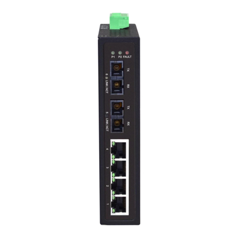
ifs NS2052-8P-2C User manual

NS2052-8P-2C User
Manual
P/N 1031-EN • REV C • ISS 03JUL22

Copyright
© 2022 Carrier. All rights reserved. Specifications subject to
change without prior notice.
This document may not be copied in whole or in part or otherwise
reproduced without prior written consent from Carrier, except
where specifically permitted under US and international copyright
law.
Trademarks and
patents
IFS names and logos are a product brand of Aritech, a part of
Carrier.
Other trade names used in this document may be trademarks or
registered trademarks of the manufacturers or vendors of the
respective products.
Manufacturer
PLACED ON THE MARKET BY:
Carrier Fire & Security Americas Corporation Inc.
13995 Pasteur Blvd, Palm Beach Gardens, FL 33418, USA
AUTHORIZED EU REPRENSENTATIVE:
Carrier Fire & Security B.V.
Kelvinstraat 7, 6003 DH Weert, Netherlands
Product warnings and
disclaimers
THESE PRODUCTS ARE INTENDED FOR SALE TO AND
INSTALLATION BY QUALIFIED PROFESSIONALS. CARRIER
FIRE & SECURITY CANNOT PROVIDE ANY ASSURANCE
THAT ANY PERSON OR ENTITY BUYING ITS PRODUCTS,
INCLUDING ANY “AUTHORIZED DEALER” OR “AUTHORIZED
RESELLER”, IS PROPERLY TRAINED OR EXPERIENCED TO
CORRECTLY INSTALL FIRE AND SECURITY RELATED
PRODUCTS.
For more information on warranty disclaimers and product safety
information, please check:
firesecurityproducts.com/policy/product-warning/ or scan the
following code:
FCC compliance
Class A: This equipment has been tested and found to comply
with the limits for a Class A digital device, pursuant to part 15 of
the FCC Rules. These limits are designed to provide reasonable
protection against harmful interference when the equipment is
operated in a commercial environment. This equipment
generates, uses, and can radiate radio frequency energy and, if
not installed and used in accordance with the instruction manual,
may cause harmful interference to radio communications.
Operation of this equipment in a residential area is likely to cause
harmful interference in which case the user will be required to
correct the interference at his own expense.
FCC conditions
This device complies with Part 15 of the FCC Rules. Operation is
subject to the following two conditions:
(1) This device may not cause harmful interference.
(2) This Device must accept any interference received, including
interference that may cause undesired operation.
ACMA compliance
Notice! This is a Class A product. In a domestic environment this
product may cause radio interference in which case the user may
be required to take adequate measures.
Certification

EU directives
Carrier Fire & Security hereby declares that this device is in
compliance with the applicable requirements and provisions of
all applicable rules and regulations, including but not limited to
the Directive 2014/53/EU. For more information see:
firesecurityproducts.com
REACH directive
Product may contain substances that are also Candidate List
substances in a concentration above 0.1% w/w, per the most
recently published Candidate List found at ECHA Web site.
Safe use information can be found at
https://firesecurityproducts.com/en/content/intrusion-intro
2006/66/EC (battery directive): This product contains a battery
that cannot be disposed of as unsorted municipal waste in the
European Union. See the product documentation for specific
battery information. The battery is marked with this symbol,
which may include lettering to indicate cadmium (Cd), lead (Pb),
or mercury (Hg). For proper recycling, return the battery to your
supplier or to a designated collection point. For more
information see: www.recyclethis.info.
2012/19/EU (WEEE directive): Products marked with this
symbol cannot be disposed of as unsorted municipal waste in
the European Union. For proper recycling, return this product to
your local supplier upon the purchase of equivalent new
equipment, or dispose of it at designated collection points. For
more information see: www.recyclethis.info.
Product documentation
Please consult the following web link to retrieve the electronic
version of the product documentation. The manuals are
available in several languages.
Contact information
EMEA: https://firesecurityproducts.com
Australian/New Zealand: https://firesecurityproducts.com.au/


NS2052-8P-2C User Manual 1
Content
Package contents 2
Hardware introduction 3
Physical dimensions 3
Switch front panel 4
LED indicators 6
Switch upper panel 7
Wiring the fault alarm contact 9
Product features 10
Installation 11
DIN-rail mounting installation 11
Wall-mount plate mounting 12
Installing the SFP transceiver 13
Removing the transceiver module 14
Troubleshooting 15
Appendix A: Networking connection 16
PoE RJ45 port pin assignments (End-span) 16
Switch’s RJ45 pin assignments 16
RJ45 cable pin assignments 17
Fiber optic cable connection parameter 18
Technical specifications 19
Important information 21
Limitation of liability 21
Product Warnings 21
Warranty Disclaimers 22
Intended Use 23
Advisory messages 23

2 NS2052-8P-2C User Manual
Package contents
Thank you for purchasing IFS industrial 8-Port 10/100TX 802.3at PoE+ plus 2-Port
Gigabit TP/SFP combo Ethernet Switch, NS2052-8P-2C. In the following sections,
the term “Industrial PoE+ Switch” means the NS2052-8P-2C.
Open the box of the Industrial PoE+ Switch and carefully unpack it. The box
should contain the following items:
1 Industrial PoE+ switch
1 User manual
1 DIN rail kit
1 Wall mounting kit
If any of these are missing or damaged, contact your dealer immediately; if
possible, retain the carton including the original packing material, and use them
again to repack the product in case there is a need to return it to us for repair.

NS2052-8P-2C User Manual 3
Hardware introduction
Physical dimensions
The physical dimensions (W x D x H) are: 66 x 107 x 152 mm

4 NS2052-8P-2C User Manual
Switch front panel
The front panel of the Industrial PoE+ Switch consists of eight 10/100/BASE-TX
ports featuring 30-watt 802.3at PoE+, and two additional Gigabit copper/SFP
combo interfaces for Gigabit Ethernet extension and video uplink. The LED
indicators are also located on the front panel of the Industrial PoE+ Switch.
Below is the front panel of Industrial PoE+ Switch (NS2052-8P-2C).
Fast Ethernet TP interfaces (Port 1 to port 8)
10/100BASE-TX copper, RJ45 twisted-pair: Up to 100 m.
Gigabit TP/SFP Combo Interfaces (Port 9 to port 10)
10/100/1000BASE-T copper, RJ45 twisted-pair: Up to 10 m.
Gigabit SFP/SFP Combo Interfaces (Port 9 to port 10)
1000BASE-SX/LX mini-GBIC slot, SFP (small factor pluggable) transceiver
module: From 550 m (multi-mode fiber) to 2/10/20/40/80/120 kilometers (single-
mode fiber).

NS2052-8P-2C User Manual 5
DIP switch
The Industrial PoE+ Switch has a built-in solid DIP switch that provides
“Standard” and “Extend” operation modes. The Industrial PoE+ Switch operates
as a normal IEEE 802.af/at PoE+ Switch in the “Standard” operation mode.
In the “Extend” operation mode, the Industrial PoE+ Switch operates on a per-
port basis at 10 Mbps full duplex operation but can support 30 W PoE power
output up to 250 m overcoming the 100 m limit on Ethernet UTP cable. With this
brand-new feature, the Industrial PoE+ Switch provides an additional solution for
802.3af/at PoE+ distance extension.

6 NS2052-8P-2C User Manual
LED indicators
Table 1: System
LED
Color
Function
P1
Green
Lit: Indicates power 1 has power.
P2
Green
Lit: Indicates power 2 has power.
FAULT
Red
Lit: Indicates neither power 1 nor power 2 has power.
Table 2: Per 802.3at PoE+ 10/100BASE-TX Interface (Port 1 to Port 8)
LED
Color
Function
LNK/ACT
Green
Lit: Indicates the link through that port is successfully established at
10 Mbps or 100 Mbps.
Blinking: Indicates that the switch is actively sending or receiving data
over that port.
PoE- in-
Use
Orange
Lit: Indicates the port is providing DC in-line power.
Off: Indicates the connected device is not a PoE powered device (PD).
Table 3: Per 10/100/1000BASE-T Interface (Shared with Port 9 to Port 10)
LED
Color
Function
LNK/ACT
Green
Lit: Indicates the link through that port is successfully established at
10/100/1000 Mbps.
Blinking: Indicates that the switch is actively sending or receiving data
over that port.
1000
Orange
Lit: Indicates the link through that port is successfully established at
1000 Mbps.
Off: Indicates the link through that port is successfully established at
10/100 Mbps.
Table 4: Per 1000X SFP Slot (Shared with Port 9 to Port 10)
LED
Color
Function
LNK/ACT
Green
Lit: Indicates the link through that port is successfully established at
1000 Mbps.
Blinking: Indicates that the switch is actively sending or receiving data
over that port.
1000
Orange
Lit: Indicates the link through that port is successfully established at
1000 Mbps.
Off: Indicates the link through that port is not established.

NS2052-8P-2C User Manual 7
Switch upper panel
The upper panel of the Industrial PoE+ Switch consists of one terminal block
connector within two DC power inputs.
Below is the upper panel of the Industrial PoE+ Switch.
Wiring the Power Inputs
The 6-contact terminal block connector on the top panel of Industrial PoE+ Switch
is used for two DC redundant power inputs. Follow the steps below to insert the
power wire.
WARNING: When performing any of the procedures like inserting the wires or
tightening the wire-clamp screws, make sure the power is OFF to prevent from
getting an electric shock.

8 NS2052-8P-2C User Manual
1. Insert positive and negative DC power wires into Contacts 1 and 2 for Power 1,
or Contacts 5 and 6 for Power 2.
2. Tighten the wire-clamp screws to prevent the wires from loosening.
1
2
3
4
5
6
Power 1
Fault
Power 2
+
-
+
-
Note: The wire gauge for the terminal block should be between 12 and 24 AWG.
The DC power input range is 48 to 56 VDC.

NS2052-8P-2C User Manual 9
Grounding the Device
For equipment protection, the device must be properly grounded, otherwise a
lightning strike could severely damage the equipment.
Wiring the fault alarm contact
The fault alarm contacts are in the middle of the terminal block connector as
shown below. When the wires are inserted, the Industrial PoE+ Switch will detect
the fault status of the power failure and open the circuit. The following illustration
shows an application example for wiring the fault alarm contacts.
Note: The wire gauge for the terminal block should be between 12 and 24 AWG.
Alarm relay circuit accepts up to 30 V with a maximum current of 3 A.

10 NS2052-8P-2C User Manual
Product features
Physical port
oEight 10/100BASE-TX Fast Ethernet RJ45 ports with IEEE 802.3at/af
PoE+ injector function (Port-1 to Port-8)
oTwo 10/100/1000BASE-T Gigabit Ethernet RJ45 ports (Port-9 and Port-
10)
oTwo 1000BASE-X mini-GBIC/SFP slots for SFP type auto detection
(Port-9 and Port-10)
Power over Ethernet
oComplies with IEEE 802.3at Power over Ethernet Plus, end-span PSE
oBackward compatible with IEEE 802.3af Power over Ethernet
oUp to eight ports of IEEE 802.3af/802.3at devices powered
o240 W PoE budget
oSupports PoE power up to 30 W for each PoE port
oAuto detects PD
oCircuit protection prevents power interference between ports
oRemote power feeding up to 100 m
Industrial case and installation
oIP30 metal case
oDIN-rail and wall-mount designs
o48 to 56 VDC, redundant power with reverse polarity protection
oSupports 6000 VDC Ethernet ESD protection
o-40 to 75C° operating temperature
Switching
oHardware-based 10/100 Mbps (half/full duplex), 1000 Mbps (full duplex),
auto-negotiation and auto MDI/MDI-X
oFeatures Store-and-Forward mode with wire-speed filtering and
forwarding rates
oIEEE 802.3x flow control for full duplex operation and back pressure for
half duplex operation
o16K MAC address table size
o10K jumbo frame
oIEEE 802.1Q VLAN transparency
oHardware-based DIP switch for “Standard” and “Extend” mode selection;
the “Extend” mode features 30-watt PoE transmission distance of 250 m
at speed of 10 Mbps
oAutomatic address learning and address aging
oSupports CSMA/CD protocol

NS2052-8P-2C User Manual 11
Installation
This section describes the functionalities of the Industrial PoE+ Switch’s
components and guides you to installing it on the DIN-rail and wall. Basic
knowledge of networking is assumed. Read this section completely before
continuing.
Note: The following pictures show how to install the device. However, the device in
the pictures is not NS2052-8P-2C.
DIN-rail mounting installation
The DIN-rail bracket is screwed on the Industrial PoE+ Switch when out of factory.
When replacing the wall-mount application with DIN-rail application, Industrial
PoE+ Switch is needed. Refer to the following figures to screw the DIN-rail bracket
on the Industrial PoE+ Switch. To hang the Industrial PoE+ Switch, follow these
steps:
1. Screw the DIN-rail bracket on the Industrial PoE+ Switch.
2. Lightly insert the bottom of the switch into the track.

12 NS2052-8P-2C User Manual
3. Make sure the DIN-rail bracket is tightly secured on the track.
4. Refer to the following procedure to remove the Industrial PoE+ Switch from the
track.
5. Lightly pull out the bottom of the switch for removing it from the track.
Wall-mount plate mounting
To install the Industrial PoE+ Switch on the wall, follow the instructions described
below.
1. To remove the DIN-rail bracket from the Industrial PoE+ Switch, loosen the
screws to remove the DIN-rail bracket.
2. Place the wall-mount plate on the back panel of the Industrial PoE+ Switch.
3. Use the screws to screw the wall-mount plate on the Industrial PoE+ Switch.

NS2052-8P-2C User Manual 13
4. Use the hook holes at the corners of the wall-mount plate to hang the Industrial
PoE+ Switch on the wall.
5. To remove the wall-mount plate, reverse the steps above.
Installing the SFP transceiver
This section describes how to insert an SFP transceiver into an SFP slot.
The SFP transceivers are hot-pluggable and hot-swappable. You can plug in and
out the transceiver to/from any SFP port without having to power down the
Industrial PoE+ Switch, as shown below.
IFS Industrial PoE+ Switch supports 1000 Mbps mode with both single mode and
multi-mode SFP transceivers.
1. Before connecting Industrial PoE+ switch to the other network device, make
sure both sides of the SFP transceivers are with the same media type, for
example, 1000BASE-SX to 1000BASE-SX, 1000BASE-LX to 1000BASE-LX.
2. Check whether the fiber-optic cable type matches with the SFP transceiver
requirement.
To connect to 1000BASE-SX SFP transceiver, use the multi-mode fiber
cable with one side being the male duplex LC connector type.
To connect to 1000BASE-LX or 1000BASE-BX SFP transceiver, use the
single-mode fiber cable with one side being the male duplex LC connector
type
Connecting the fiber cable
1. Insert the duplex LC connector into the SFP transceiver.
2. Connect the other end of the cable to a device with a SFP transceiver installed.
3. Check the LNK/ACT LED of the SFP slot on the front of the Industrial PoE+
Switch. Ensure that the SFP transceiver is operating correctly.
4. Check the Link mode of the SFP port if the link fails.

14 NS2052-8P-2C User Manual
Note: It is recommended to use IFS SFPs on the Industrial PoE+ Switch. If you
insert an SFP transceiver that is not supported, the Industrial PoE+ Switch will not
recognize it.
Removing the transceiver module
1. Make sure there is no network activity by consulting or checking with the
network administrator. Or through the management interface of the
switch/converter (if available) to disable the port in advance.
2. Gently remove the fiber optic cable.
3. Turn the lever of the SFP series module to a horizontal position.
4. Pull out the module gently through the lever.
Note: Never pull out the module without pulling the lever or the push bolts on the
module. Directly pulling out the module with force could damage the module and
the SFP module slot of the Industrial PoE+ Switch.

NS2052-8P-2C User Manual 15
Troubleshooting
This section contains information to help you solve issues. If the Industrial PoE+ Switch
is not functioning properly, make sure the Industrial PoE+ Switch was set up according
to instructions in this manual.
The per port LED is not lit
Solution: Check the cable connection of the Industrial PoE+ Switch.
Per port LED is lit, but the traffic is irregular
Solution: Check whether the attached device is not set to dedicated full duplex. Some
devices use a physical or software switch to change duplex modes. Auto-negotiation
may not recognize this type of full-duplex setting.
Why the Industrial POE+ Switch does not connect to the network
Solution: Check each port LED on the Industrial PoE+ Switch. Try another port on the
Industrial PoE+ Switch. Make sure that the cable is installed properly and is the correct
type. Turn off the power. After a while, turn on the power again.

16 NS2052-8P-2C User Manual
Appendix A: Networking connection
PoE RJ45 port pin assignments (End-span)
Table 5: PoE RJ45 port pin assignments (End-span)
PIN NO
RJ45 POWER ASSIGNMENT
1
˙Power +
2
˙Power +
3
˙Power -
6
˙Power -
PIN NO
RJ45 POWER ASSIGNMENT
Switch’s RJ45 pin assignments
Table 6: 1000Mbps, 1000BASE-T
Contact
MDI
MDI-X
1
BI_DA+
BI_DB+
2
BI_DA-
BI_DB-
3
BI_DB+
BI_DA+
4
BI_DC+
BI_DD+
5
BI_DC-
BI_DD-
6
BI_DB-
BI_DA-
7
BI_DD+
BI_DC+
8
BI_DD-
BI_DC-
Table 7: 10/100Mbps, 10/100BASE-TX
RJ45 Connector pin assignment
Contact
MDI
Media Dependent
Interface
MDI-X
Media Dependent Interface --
Cross
1
Tx + (transmit)
Rx + (receive)
2
Tx - (transmit)
Rx - (receive)
3
Rx + (receive)
Tx + (transmit)
4, 5
Not used
6
Rx - (receive)
Tx - (transmit)
7, 8
Not used
Table of contents
Other ifs Switch manuals
ifs
ifs NS4750-24S-4T-4X-V2 User manual
ifs
ifs ES2402-V3 Series User manual
ifs
ifs NS3500-24T-4C-V2 User manual
ifs
ifs POC2502 Series User manual
ifs
ifs NS4702-24P-4X-V2 User manual
ifs
ifs NS3550-8T-2S-V2 User manual
ifs
ifs NS3552-16P-2T-2S-V2 User manual
ifs
ifs NS3562-8P-2S-V2 User manual
ifs
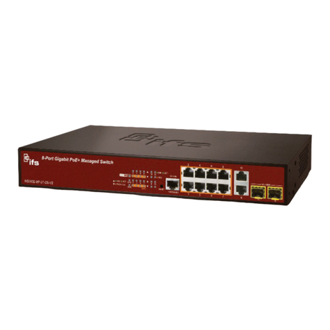
ifs NS3502-8P-2T-2S-V2 User manual

ifs
ifs NS3702-24P-4S-V3 User manual
