manuals.online logo
Brands
  1. Home
  2. •
  3. Brands
  4. •
  5. ifs
  6. •
  7. Switch
  8. •
  9. ifs NS4802-24P-4S-2X User manual

ifs NS4802-24P-4S-2X User manual

P/N 1073041-EN • REV C • ISS 17JUN21 1 / 4
NS4802-24P-4S-2X Quick Installation Guide
Package contents
Thank you for purchasing the IFS NS4802-24P-4S-2X L2+ 24-
port 10/100/1000T 802.3at PoE + 2-Port 10G SFP+ Stackable
Managed Switch. The description of this model is as follows:
L2+ 24-port 802.3at 10/100/1000T PoE
+ 2-Port 10G SFP+ Stackable Managed Switch
Unless specified, the term “stackable managed switch”
mentioned in this quick installation guide refers to the S4802-
24P-4S-2X.
Open the box of the stackable managed switch and carefully
unpack it. The box should contain the following items:
The stackable managed switch × 1
Quick installation guide × 1
CD with user manual × 1
RJ45 to RS232 cable × 1
Rubber feet × 4
Two rack-mounting brackets with attachment screws x 1
Power cord × 1
SFP dust-proof cap × 8
If any of these are missing or damaged, contact your dealer
immediately. If possible, retain the carton including the original
packing materials for repacking the product in case there is a
need to return it to us for repair.
Requirements
The stackable managed switch provides a remote login
interface for management purposes. The following equipment
is necessary for further management:
Workstations running Windows®XP / 2003 / Vista / 7 / 8 /
2008 / 10, MAC OS X or later, Linux, UNIX, or other
platforms compatible with TCP/IP protocols.
Workstations are installed with Ethernet NIC (Network
Interface Card)
Serial port connection (Terminal)
The above workstations come with a COM Port (DB9)
or USB-to-RS232 converter.
The above workstations have been installed with a
terminal emulator, such as Hyper Terminal included in
Windows XP/2003.
Serial cable – One end is attached to the RS232
serial port, and the other end is attached to the
console port of the stackable managed switch.
Ethernet port connection
Network cables – Use standard network (UTP) cables
with RJ45 connectors.
The above workstations have a Web browser and
JAVA runtime environment plug-in installed.
Note: We recommend using Internet Explorer 8.0 or later to
access the stackable managed switch. If the web interface of
the stackable managed switch is not accessible, turn off the
anti-virus software or firewall and then try it again.
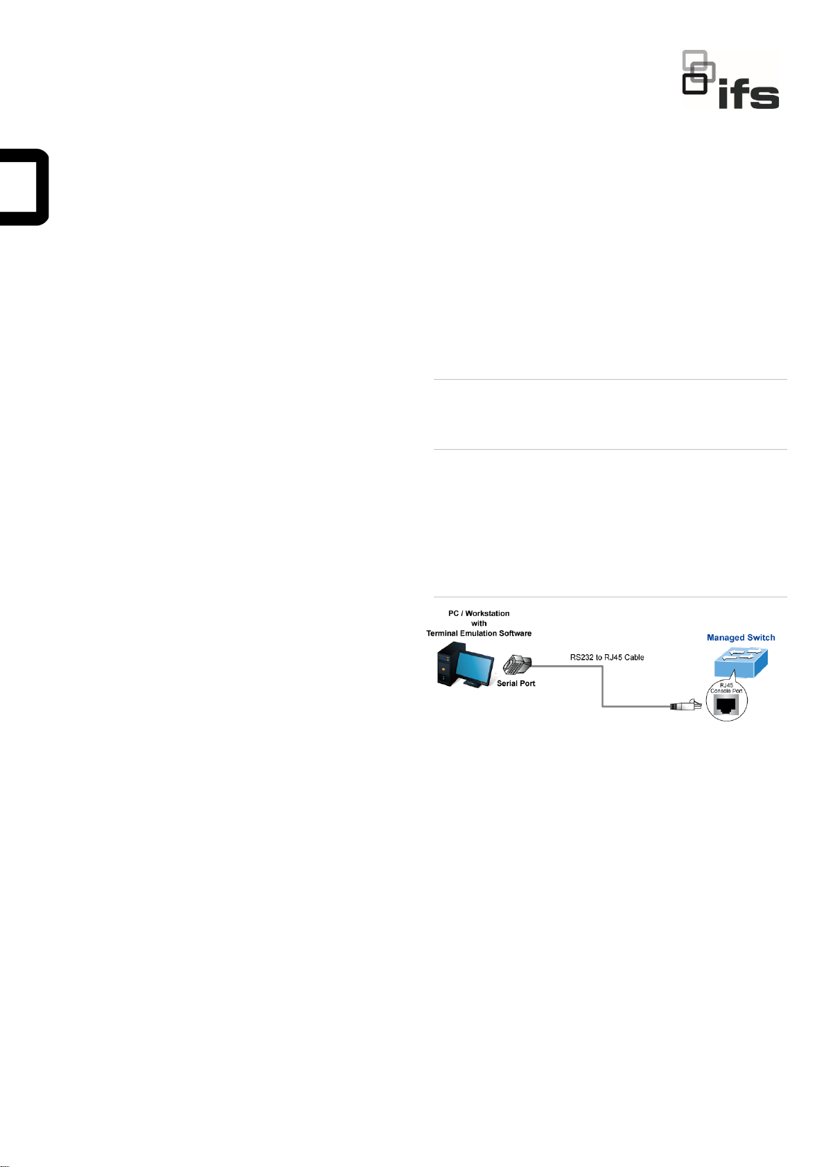
Terminal setup
To configure the system, connect a serial cable to a COM port
on a PC or notebook computer and to a RJ45 type serial port
on the stackable managed switch.
Figure 1: Console connectivity
A terminal program is required to make the software
connection to the stackable managed switch. Windows' Hyper
Terminal program may be a good choice. The Hyper Terminal
can be accessed from the Start menu.
1. Click Start > Programs > Accessories > Hyper
Terminal.
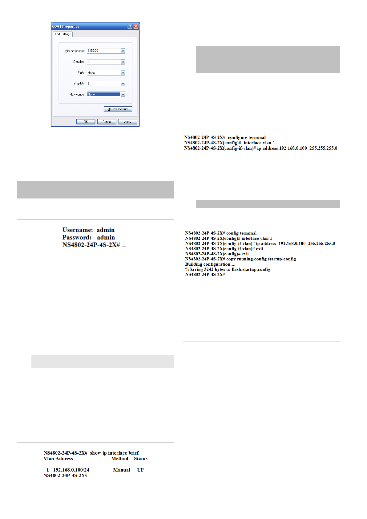
2. When the following screen appears, ensure that the COM
port is configured as shown below. Click OK when finished
with configuration.
• Baud : 115200
• Data bits : 8
• Parity : None
• Stop bits : 1
• Flow control : None
2 / 4 P/N 1073041-EN • REV C • ISS 17JUN21
3. Log in to the console. After the terminal has been
connected to the device, power on the managed stackable
switch. The terminal displays “running testing procedures”.
When the following dialog box in Figure 2 below appears,
type the factory default user name "admin" and password
“admin”.
User name: admin
Password: admin
Figure 2: Console login screen
Note:
1. For security purposes, change and memorize the new
password after this first setup.
2. Only commands in lowercase letters are accepted in the
console interface.
Configuring the IP address
The managed stackable switch is shipped with the default IP
address shown below:
IP Address: 192.168.0.100
Subnet Mask: 255.255.255.0
To check the current IP address or modify a new IP address
for the managed stackable switch, use the following
procedures:
Display of the current IP Address
1. At the “#” prompt, type “show ip interface brief”.
2. The screen displays the current IP address.
Figure 3: IP information screen
Configuration of the IP address
3. At the “#” prompt, type the following command and press
Enter as shown in Figure 5.
Switch# configure terminal
Switch(config)# interface vlan 1
Switch(config-if-vlan)# ip address 192.168.0.100
255.255.255.0
The previous command would apply the following settings
for the stackable managed switch.
IP Address: 192.168.0.100
Subnet Mask: 255.255.255.0
Figure 4: Configuring the IP address screen
4. Repeat step 1 to check if the IP address has changed.
Store the current switch configuration
5. At the “#” prompt, type the following command and press
Enter.
# copy running-config startup-config
Figure 5: Saving current configuration command screen
If the IP is successfully configured, the managed stackable
switch applies the new IP address setting immediately. Access
the web interface of the stackable managed switch through the
new IP address.
Note: If unfamiliar with the console command or the related
parameter, type “help” in the console to obtain the Help
description.
Starting web management
The section describes how to start up the web management
function for the stackable managed switch. Note that the
stackable managed switch is configured through an Ethernet
connection. Ensure that the manager computer is set to the
same IP subnet address.
For example, if the default IP address of the stackable
managed switch is 192.168.0.100, then the manager computer
should be set to 192.168.0.x (where x is a number between 1
and 254, except 100), and the default subnet mask is
255.255.255.0.
P/N 1073041-EN • REV C • ISS 17JUN21 3 / 4
Figure 6: IP management diagram
Logging in to the managed stackable switch
1. Use the Internet Explorer 8.0 or later Web browser and
type the IP address http://192.168.0.100 (the factory-
default IP address) to access the Web interface.
2. When the following dialog box appears, enter the default
user name “admin” and password “admin” (or the
password you have changed before) as shown in Figure 7
below.
Default IPAddress: 192.168.0.100
Default User Name: admin
Default Password: admin
Figure 7: Login screen
3. After typing the password, the main screen appears as
shown in Figure 8 below.
Figure 8: Main web interface screen
4. The switch menu on the left side of the web page permits
access to all the functions and status provided by the
stackable managed switch.
Figure 9: Main menu
Refer to the User Manual or click the Help button for further
information about using the web management interface.
Note: For security purposes, change and memorize the new
password after this first setup.
Saving the configuration
The running configuration file is stored in the RAM of the
stackable managed switch. In the current version, the running
configuration sequence of running-config can be saved from
the RAM to FLASH by executing the Save Startup Config
command. After doing this, the running configuration sequence
becomes the startup configuration file (i.e., the saved
configuration).
To save all applied changes and set the current configuration
as a startup configuration, the startup-configuration file is
loaded automatically across a system reboot.
1. Click System > Save Startup Config.
4 / 4 P/N 1073041-EN • REV C • ISS 17JUN21
2. Click the Save Configuration button.
Resetting the switch to default
To reset the IP address to the default IP address
“192.168.0.100” and the user password to factory default mode
(default password is “admin”), press the hardware reset button
on the front panel for about 10 seconds. After the device is
rebooted, log in to the management Web interface within the
same subnet of 192.168.0.xx and default password. Note that
all the previous setups are erased after the factory default
reset.
Figure 10: Reset button
Contact information
EMEA: https://firesecurityproducts.com
Australian/New Zealand: https://firesecurityproducts.com.au/
Legal information
Copyright
©
2021 Carrier. All rights reserved.
Specifications subject to change without prior
notice
.
This document may not be copied in whole or in
part or otherwise reproduced without prior
written consent from
Carrier, except where
specifically permitted under US and
international copyright law.
Trademarks and
patents
IFS
names and logos are a product brand of
Aritech, a part of
Carrier.
Other trade names used in this document may
be trademarks or registered trademarks of the
manufacturers or vendors of the respective
products.
Manufacturer
PLACED ON THE MARKET BY:
Carrie
r Fire & Security Americas Corporation
Inc.
13995 Pasteur Blvd, Palm Beach Gardens, FL
33418, USA
AUTHORIZED EU REPRENSENTATIVE:
Carrier Fire & Security B.V.
Kelvinstraat 7, 6003 DH Weert, Netherlands
Certification
2012/19/EU (WEEE directive):
Products
marked with this symbol cannot be disposed of
as unsorted municipal waste in the European
Union. For proper recycling, return this product
to your local supplier upon the purchase of
equivalent new equipment, or dispos
e of it at
designated collection points. For more
information see: www.recyclethis.info.
Product
documentation
Please consult the following web link to retrieve
the electronic version of the product
documentation.
The manuals are available in
several languages.

Other ifs Switch manuals

ifs NS3550-8T-2S-V2 User manual

ifs

ifs NS3550-8T-2S-V2 User manual

ifs NS3502-8P-2T-2S-V2 User manual

ifs

ifs NS3502-8P-2T-2S-V2 User manual

ifs NS2052-8P-2C User manual

ifs

ifs NS2052-8P-2C User manual

ifs NS3552-16P-2T-2S-V2 User manual

ifs

ifs NS3552-16P-2T-2S-V2 User manual

ifs ES2402-V3 Series User manual

ifs

ifs ES2402-V3 Series User manual

ifs NS3562-8P-2S-V2 User manual

ifs

ifs NS3562-8P-2S-V2 User manual

ifs NS3502-8P-2T-2S-V3 User manual

ifs

ifs NS3502-8P-2T-2S-V3 User manual

ifs NS3503-16P-4C-V2 User manual

ifs

ifs NS3503-16P-4C-V2 User manual

ifs NS4702-24P-4X-V2 User manual

ifs

ifs NS4702-24P-4X-V2 User manual

ifs NS3702-24P-4S-V3 User manual

ifs

ifs NS3702-24P-4S-V3 User manual

ifs NS3500-24T-4C-V2 User manual

ifs

ifs NS3500-24T-4C-V2 User manual

ifs NS3562-8P-2S-V2 User manual

ifs

ifs NS3562-8P-2S-V2 User manual

ifs NS4750-24S-4T-4X-V2 User manual

ifs

ifs NS4750-24S-4T-4X-V2 User manual

ifs POC2502 Series User manual

ifs

ifs POC2502 Series User manual

Popular Switch manuals by other brands

CVS CVS 870 instruction manual

CVS

CVS CVS 870 instruction manual

Kramer VP-438 user manual

Kramer

Kramer VP-438 user manual

Crestron DigitalMedia DM-MD64X64 Getting started

Crestron

Crestron DigitalMedia DM-MD64X64 Getting started

Avaya P334T-ML quick start

Avaya

Avaya P334T-ML quick start

UltraLux SCRF2 quick start guide

UltraLux

UltraLux SCRF2 quick start guide

Honeywell miniMAX Quick start configuration guide

Honeywell

Honeywell miniMAX Quick start configuration guide

evertz 7700 Series manual

evertz

evertz 7700 Series manual

Cisco IE 2000 Release notes

Cisco

Cisco IE 2000 Release notes

BD Sensors DM01 operating manual

BD Sensors

BD Sensors DM01 operating manual

Anigmo AE-2400R quick guide

Anigmo

Anigmo AE-2400R quick guide

D-Link DAS-3626 user manual

D-Link

D-Link DAS-3626 user manual

Garmin GSB 15 installation manual

Garmin

Garmin GSB 15 installation manual

Vimar Eikon TACTIL 21119 manual

Vimar

Vimar Eikon TACTIL 21119 manual

ATEN CS72D user manual

ATEN

ATEN CS72D user manual

Altusen KN9000 user manual

Altusen

Altusen KN9000 user manual

PowerDsine PD-6548 user guide

PowerDsine

PowerDsine PD-6548 user guide

Allied Telesis AT-9424T AC datasheet

Allied Telesis

Allied Telesis AT-9424T AC datasheet

SignaMax CommandView FO-098-8080 user guide

SignaMax

SignaMax CommandView FO-098-8080 user guide

manuals.online logo
manuals.online logoBrands
  • About & Mission
  • Contact us
  • Privacy Policy
  • Terms and Conditions

Copyright 2025 Manuals.Online. All Rights Reserved.