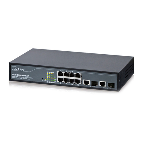
ifs NS3562-8P-2S-V2 User manual

P/N 1073703-EN • REV B • ISS 13JUL22 1
NS3562-8P-2S-V2 Quick Installation
Guide
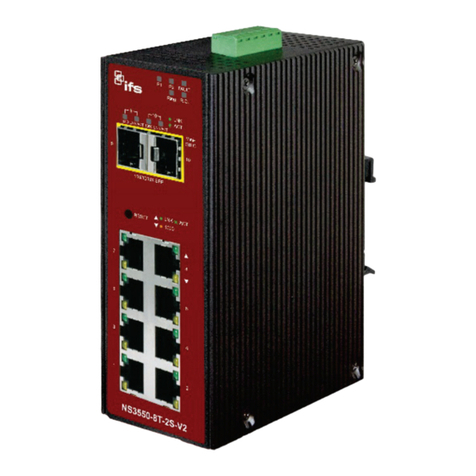
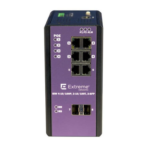
Figure 1: NS3562-8P-2S-V2 Industrial Managed Switch
Package contents
Thank you for purchasing the IFS NS3562-8P-2S-V2
industrial managed switch. The description of this model
is as follows: Industrial 8-Port 10/100/1000T 802.3at
PoE + 2-Port 100/1000X SFP Managed Gigabit Switch.
Unless specified, the term “industrial managed switch”
mentioned in this quick installation guide refers to the
NS3562-8P-2S-V2.
Open the box of the industrial managed switch and
carefully unpack it. The box should contain the following
items:
The industrial managed switch × 1
Quick installation guide × 1
DIN-rail kit × 1
Magnet kit × 1
Wall mounting kit × 1
RJ45 dust cap × 8
SFP dust cap × 2
If any item is found missing or damaged, please contact
your local reseller for replacement.
Requirements
Workstations running Windows®10 / 7 / 8 / 2008 /
Vista / 2003 / XP, MAC OS Xor later, Linux, UNIX,
or other platforms are compatible with TCP/IP
protocols
Workstations are installed with Ethernet NIC
(Network Interface Card)
Ethernet Port Connection
Network cables - Use standard network (UTP)
cables with RJ45 connectors.
The above workstation has a Web browser and
JAVA runtime environment plug-in installed.
Note: We recommend using Internet Explorer11.0 or
later to access the industrial managed switch. If the Web
interface of the industrial managed switch is not
accessible, turn off the anti-virus software or firewall and
then try it again.
Wiring the power inputs
The industrial managed switch features a strong dual
power input system (terminal block and DC jack) to
enhance system reliability and uptime.
Range model
Power Input
3-pin terminal block DC jack
NS3562-8P-2S-V2 48~56 VDC 48~56 VDC

2 NS3562-8P-2S-V2 Quick Installation Guide
Figure 2: DC power input
V+ = Positive / V- = Negative / Ground
Terminal block connector pinout
To install the 3-pin terminal block connector on the
industrial managed switch, follow these steps:
1. Insert positive DC power wire into V+, negative DC
power wire into V-, and grounding wire into Ground.
2. Tighten the wire-clamp screws for preventing the
wires from loosening and plug into the industrial
managed switch.
Note:
1. The wire gauge should be in the range from 12 to 24
AWG.
2. The device must be grounded.
Mounting
Note: Ensure that the industrial managed switch is
mounted vertically with the air holes on the top and a
minimum of three inches above and below the switch to
allow for proper air flow. This device uses a convection
flow of hot air which rises and brings cold air in from the
bottom and out of the top of the device. Do not mount
the switch horizontally as this does not allow air to flow
up into the device and will result in damage to the
switch. Do not tie DC1 to DC2. DC2 is for secondary
power redundancy. Do not plug DC power into the
device while the AC power cord is plugged in. This is not
a hot-swappable switch. Hot-swapping this device will
result in damage.
Wall mount installation
To install the industrial managed switch on the wall,
follow these steps:
1. There are four holes with an 8 mm diameter on the
wall; the distance between the two holes is 133 mm
and the line through them must be horizontal.
2. Install a conductor pipe inside the board hole and
flush the edge of the conductor pipe with the wall
surface.
3. Screw the bolts into the conductor pipe. The
industrial managed switch is between the bolts and
conductor pipe, as shown below.
Figure 3: Wall mount installation
Magnet installation
Figure 4below demonstrates how to install the industrial
managed switch on a magnetic surface.
Figure 4: Magnet installation
DIN-rail mount installation
The DIN-rail kit is included in the package. When the
industrial application for the industrial managed switch
needs to be replaced with aDIN-rail application, refer to
the following illustrations to screw the DIN-rail on the
industrial managed switch. To hangup the industrial
managed switch, follow the steps below:
1. Screw the DIN-rail on the industrial managed switch.

NS3562-8P-2S-V2 Quick Installation Guide 3
2. Lightly insert the button of the DIN-rail into the track.
3. Ensure that the DIN-rail is secured tightly on the
track.
Starting Web management
The following section describes how to start up the Web
management function of the industrial managed switch.
Note that the industrial managed switch is configured
through an Ethernet connection. Ensure that the
manager computer is set to the same IP subnet address.
For example, if the default IP address of the industrial
managed switch is 192.168.0.100,then the manager
computer should be set to 192.168.0.x (where x is a
number between 1 and 254, except 100) and the default
subnet mask is 255.255.255.0.
Figure 5: IP management diagram
Logging in to the industrial managed switch
1. Use the Internet Explorer 11.0 or later Web browser
and type the IP address http://192.168.0.100 to
access the Web interface.
2. When the following dialog box appears, type the
default user name “admin” and password “admin” (or
the password you have changed before)as shown
in Figure 8 below.
Default IP Address: 192.168.0.100
Default User Name: admin
Default Password: admin
Note: Before connecting to a TruVision Navigator
video surveillance system network, the default IP
address must be changed to the IP address
assigned for TruNav by the network administrator.
Figure 6: Login screen
3. If logged in to the switch via web or console with the
default account (admin / admin), a warning message
appears to notify the user to change the user name
and password. Click OK.
4. Type a new user name and password in the Edit
User page, following the guidelines as shown. Click
Apply.

4NS3562-8P-2S-V2 Quick Installation Guide
5. After typing the password, the main screen appears
as shown in Figure 9 below.
Figure 7: Main web interface screen
6. The switch menu on the left side of the web page
permits access to all the functions and status
provided by the managed switch.
Refer to the User Manual for further information about
using the web management interface.
Note: For security purposes, change and memorize the
new password after this first setup.
Saving configuration via the Web
In the industrial managed switch, the running
configuration file is stored in the RAM. In the current
version, the running configuration sequence of running-
config can be saved from the RAM to FLASH bythe by
executing the Save Startup Config command. After
doing this, the running configuration sequence becomes
the startup configuration file (i.e., the saved
configuration).
To save all applied changes and set the current
configuration as a startup configuration;the startup-
configuration file will be loaded automatically across a
system reboot.
1. Click System > Save Startup Config.
2. Click the Save Configuration button.
Reset to default configuration
If an IP address has been changed or an admin
password has been forgotten, the IP address can be
reset.
To reset the IP address to the default IP address
“192.168.0.100” or reset the login password to default
value, press the RESET button on the front panel for
about five seconds.After the device is rebooted,log in to
the management web interface within the same subnet
of 192.168.0.xx.
Figure 8: NS3562-8P-2S-V2 Reset Button

NS3562-8P-2S-V2 Quick Installation Guide 5
Legal and regulatory
information
Copyright
©
2022 Carrier. All rights reserved.
Specifications subject to change without prior
notice
.
This document may not be copied in whole or in
part or otherwise reproduced without prior
written consent from
Carrier, except where
specifically permitted under US and
international copyright law.
Trademarks and
patents
IFS
names and logos are a product brand of
Aritech, a part of
Carrier.
Other trade names used in this document may
be tradema
rks or registered trademarks of the
manufacturers or vendors of the respective
products.
Manufacturer
PLACED ON THE MARKET BY:
Carrier Fire & Security Americas Corporation
Inc.
13995 Pasteur Blvd, Palm Beach Gardens, FL
33418, USA
AUTHORIZED EU REPRENSEN
TATIVE:
Carrier Fire & Security B.V.
Kelvinstraat 7, 6003 DH Weert, Netherlands
Certification
2012/19/EU (WEEE directive):
Products
marked with this symbol cannot be disposed of
as unsorted municipal waste in the European
Union. For
proper recycling, return this product
to your local supplier upon the purchase of
equivalent new equipment, or dispose of it at
designated collection points. For more
information see: www.recyclethis.info.
Product
documentation
Please consult the following web link to retrieve
the electronic version of the product
documentation.
The manuals are available in
several languages.
Other manuals for NS3562-8P-2S-V2
1
Table of contents
Other ifs Switch manuals
ifs
ifs NS4750-24S-4T-4X-V2 User manual

ifs
ifs NS3702-24P-4S-V3 User manual
ifs
ifs NS3562-8P-2S-V2 User manual
ifs
ifs NS4702-24P-4X-V2 User manual
ifs
ifs NS3503-16P-4C-V2 User manual
ifs
ifs ES2402-V3 Series User manual
ifs
ifs NS3502-8P-2T-2S-V2 User manual
ifs
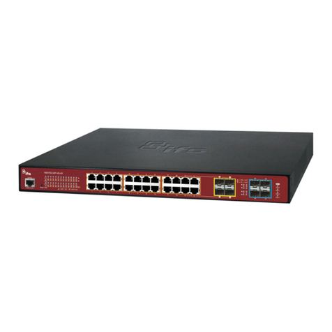
ifs NS4802-24P-4S-2X User manual
ifs
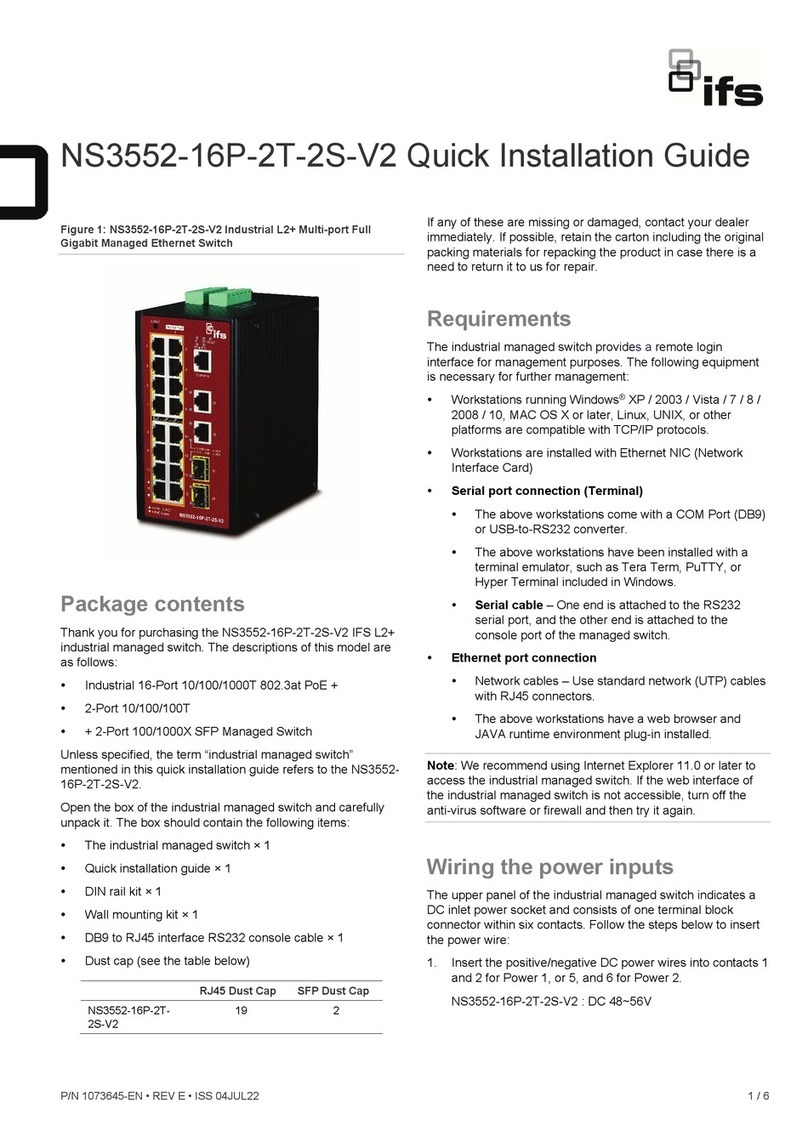
ifs NS3552-16P-2T-2S-V2 User manual
ifs
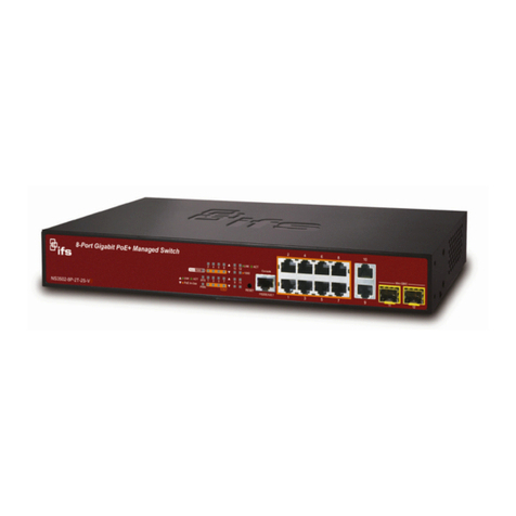
ifs NS3502-8P-2T-2S-V3 User manual
