IGM Professional FMR3000 MultiRadius User manual

man_FMR3000_A5br_EN+DE+FR+CZ+SK+HU+PL_v2.6
ELLIPSE AND CIRCLE CUTTING JIG
FMR3000 MultiRadius
ELLIPSENUND KREISFRÄSHILFE
FMR3000 MultiRadius
DISPOSITIF POUR FRAISER ELLIPSES ET CERCLES
FMR3000 MultiRadius
ZAŘÍZENÍ PRO FRÉZOVÁNÍ ELIPS A KRUHŮ
FMR3000 MultiRadius
ZARIADENIE PRE FRÉZOVANIE ELÍPS A KRUHOV
FMR3000 MultiRadius
KÉSZÍTMÉNY ELLIPSZISEK ÉS KÖRVONALAK MARÁSÁRA
FMR3000 MultiRadius
PRZYRZĄD DO WYCINANIA ELIPS I OKRĘGÓW
FMR3000 MultiRadius
FMR3000
Operationg instructions EN p. 2 - 5
Gebrauchsanweisung DE S. 6 - 9
Mode d‘emploi FR s. 10 - 13
Návod k obsluze CZ s. 14 - 17
Návod na obsluhu SK s. 18 - 21
Használati útmutató
HU o.
22 - 25
Instrukcja obsługi PL s. 26 - 29
www.igm.cz
2
Operating instructions EN
www.igmtools.com
7.
CONTENTS PAGE
Package contents 2
JIG ASSEMBLY 2
Cutting of circular curves 3
Cutting ellipses 3
Safety 5
Spare parts list 5
DESCRIPTION
The jig is designed for cutting circles and ellipses at circumference or on the front side of the piece. It extends
the possibilities of the portable router and increases the quality of the machined surface as well as the
precision of the cut form. The basis of the whole jig system is the sliding cross frame made of special plastic.
Special sliders A+ Bare shifted within this cross frame.
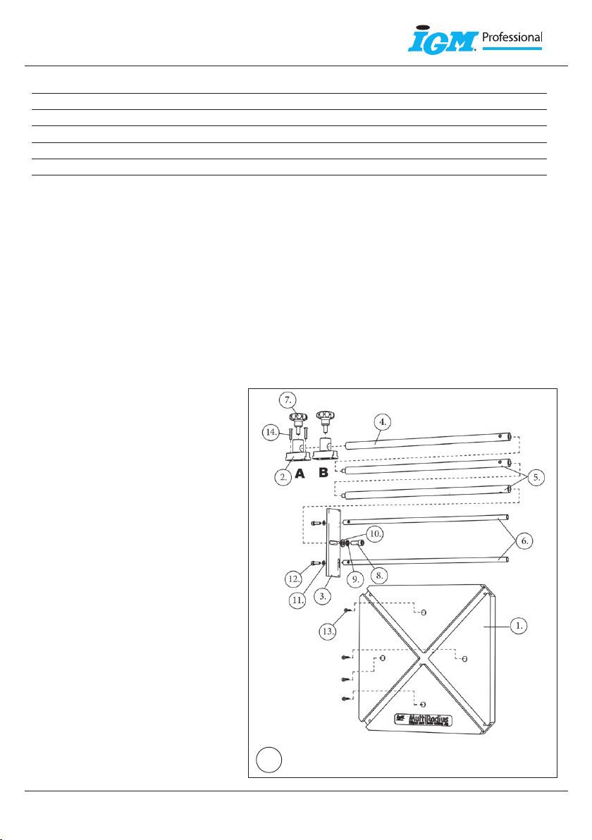
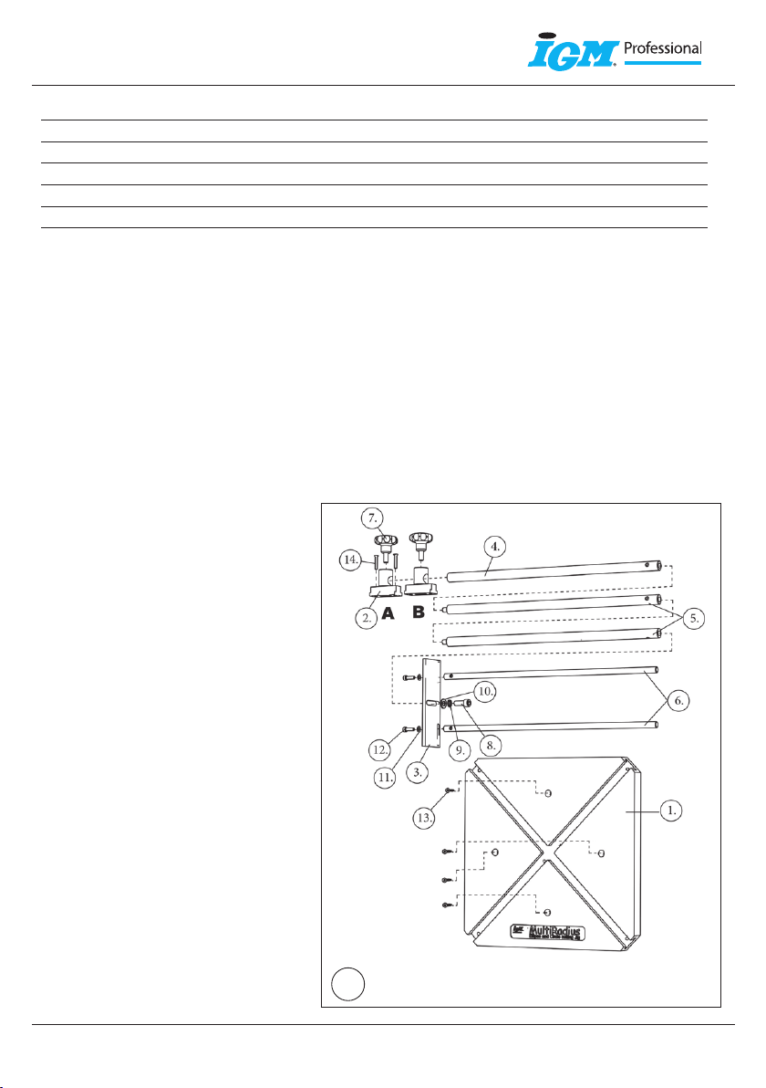
PACKAGE CONTENTS
1 pc (1) Cross frame made of special plastic
2 pc (6) Guide rods D=10mm (upon request 8 mm ) L= 400 mm
2 pc (5) Distance rods with L =400 mm screw
1 pc (4) Distance rod L =400 mm
1 pc (3) Connector plate
2 pc (7) Control bolt M8
2 pc (2) Sliders – complete
1 pc (8) Imbus Screw M8x20
2 pc (12) Imbus Screw M5x16
2 pc (14) Screw M4x25 with countersink head
1 pc (10) Screw washer M8
2 pc (11) Screw washer M5
1 pc (9) Elastic screw washer M8
4 pc (13) Wood screw 4x35
JIG ASSEMBLY
(Fig. 7) Insert the guide rods D10 (6) into
the grooves of the connector plate (3)
and tighten with screws M5x16 (12) and
washers (11). Screw the control screw (7)
into the sliders (2). Put the sliders (2) into
the cross frame (1). Assemble the distance
rods D16 (5) and (4) together. Insert the
end of the distance rod with threading into
the groove of the connector plate (3) and
tighten with screw M8x20 (8) and washer
(9) and (10). Put the sliders A and B into the
guide grooves of the cross frame, insert the
distance rod into the holes in the pins of
both sliders, tighten the control screws of
the sliders. Assembly is now complete.

www.igm.cz 3
Operating instructions EN
www.igmtools.com
1. 2.
3. 4.
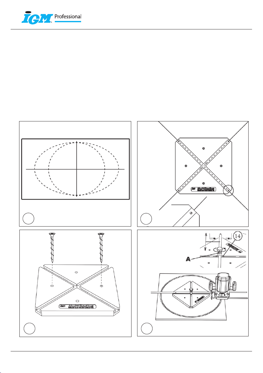
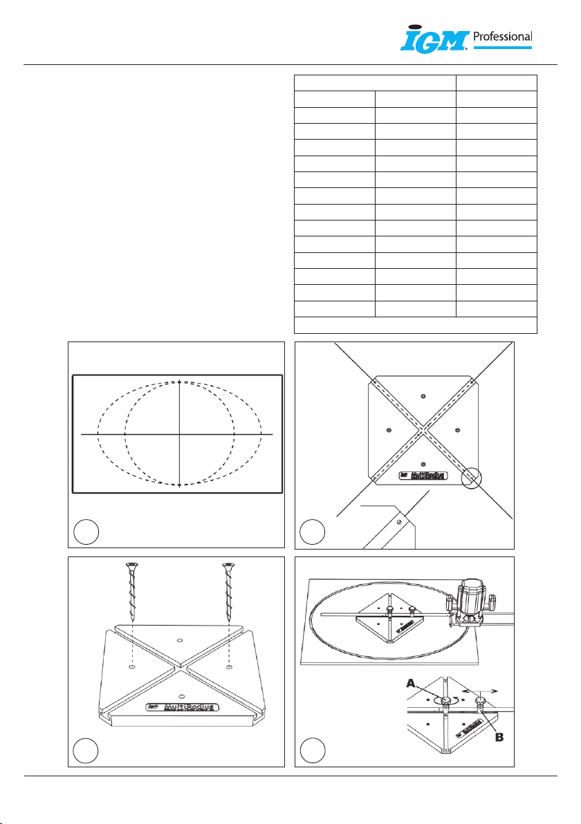
CUTTING CIRCULAR CURVES
Delineate on the work piece axis of the required circle at the angle of 90° with a sign on the required radius
(fig. 1). Affix the cross frame (1) to the work or help piece (fig. 3) with the help of wood screws (13) or with
bonding tape so that the delineated axis intersect the centre of the borings at the end of the cross frame
grooves (fig. 2).The cross frame is now centered on the circle axis. Put the slider A into the cross frame slide
way, shift it to the centre of the cross frame where the both grooves are crossing and affix to the cross frame
(1) with the help of two countersink head screws M4x25 (14). Remove the slider B from the slide way. Set the
required radius and tighten the control screw of the slider A (fig. 4).
Possible diameter of the circular curve: D = 620 – 3000 mm
CUTTING ELLIPSES
The construction design stipulates the maximum difference in the length of semi-axis of the ellipse
at 205 mm.

www.igm.cz
4
Operating instructions EN
www.igmtools.com
1. 2.
3. 5.
PROCEDURE ON CUTTING ELLIPSES
Ellipse size determination
Delineate on the work piece axis of the required ellipse
at the angle of 90° and mark the length and the width
of the ellipse (fig. 1). Affix the cross frame (1) to the
work or help piece
(fig. 3) with the help of wood screws (13) or with
bonding tape so that the delineated axis intersect the
centre of the borings at the end of the cross frame
grooves (fig. 2). The cross frame is now centered on the
ellipse axis.
Major semi-axis setting
(fig .5) Insert the slider Ainto the centre of the cross
frame and the slider Bin the direction of the major
(long) semi-axis. Loosen the control screw of the
slider A, set the required semi-axis length by shifting
the distance rod in the centre of the slider Apin and
tighten with the control screw (the screw of the slider B
is still loose and the rod passes free through the pin).
Minor axis L2 Major axis L1
MIN MAX
2590 2890 3000
1590 1890 2000
1390 1690 1800
1290 1590 1700
1090 1390 1500
990 1290 1400
890 1190 1300
790 1090 1200
690 990 1100
620 920 1030
620 790 900
620 690 800
620 620 730
Minimal possible combination

www.igm.cz 5
Operating instructions EN
www.igmtools.com
6.
Minor semi-axis setting
(fig. 6) Rotate the router by 90°. (Cross frame is not
rotated! Slider Bis in the center of the cross frame).
Set the required minor semi-axis length by shifting
the distance rod in the slider Bpin; slider Ais still
tighten! Setting finished, tighten the control screw of
the slider B.
Attention: If the work piece is bent or otherwise
crooked, after the tightening of the cross frame, the
sliders may jam in the grooves. Therefore use only
flat material!!!
!!! SAFETY AT WORK !!!
1/ Respect the safety at work indicated by the producer of your portable router and tools used.
2/ The MultiRadius jig is safe if used in accordance with all principals of safety at work with routers and router bits.
3/ Always unplug the router when setting the MultiRadius jig.
4/ Read carefully the operating instructions before using the jig.
For questions contact your distributor or directly the producer.
FMR3000 Spare parts list v.2,1
Pos. # Description Quantity in
basis pack Code
2 Sliders - complete 1 FMR3996
8, 9, 10,
11,12,13,
14
Set of screws 13 pc FMR3994
6 *Guide rod D8 mm 2 FMR3998
Guide rod D10 mm 2 FMR3000-02
5 Distance rod with screw D16x400 mm 1 FMR3997
7 Control screw M8 1 FS200 108
Drawing compass 1 FMR3009
*not included in the basic pack

www.igm.cz
6
Gebrauchsanweisung DE
www.igmtools.com
7.
INHALT PAGE
Packungsinhalt 6
AUFSTELLUNG DES GERÄTES 6
Fräsen von Kreisbögen 7
Fräsen von ellipsen 7
Sicherheit 9
Ersatzteilliste 9
BESCHREIBUNG
Das Gerät dient zum Fräsen von Kreisen und Ellipsen am Umfang oder auf der Stirnseite des Werkstückes. Es
erweitert die Möglichkeiten der Oberfräse, verbessert die Qualität der bearbeiteten Oberfläche und erhöht
die Formgenauigkeit. Die Basis des ganzen Gerätes stellt ein aus einem Sonderkunststoff hergestellter Gleit-
Kreuzrahmen dar. In diesem Kreuzrahmen werden spezielle Gleitschuhe A + B geschoben.
PACKUNGSINHALT
1 St. (1) Kreuzrahmen aus Sonderkunststoff
2 St. (6) Führungsleisten D=10 mm ( auf Wunsch 8 mm ) L= 400 mm
2 St. (5) Distanzleisten L =400 mm mit Schraube
1 St. (4) Distanzleiste L =400 mm
1 St. (3) Gabelhalter
2 St. (7) Steuerungsschraube M8
2 St. (2) Gleitschuhe – komplett
1 St. (8) Imbus Schraube M8x20
2 St. (12) Imbus Schraube M5x16
2 St. (14) Schraube M4x25 mit Versenkkopf
1 St. (10) Schraubenunterlage M8
2 St. (11) Schraubenunterlage M5
1 St. (9) Elastische Schraubenuterlage M8
4 St. (13) Holzschraube 4x35
AUFSTELLUNG DES GERÄTES
(Abb. 7) Führungsleisten D10 (6) in
die Längsnuten des Gabelhalters (3)
einschieben und mit Schrauben M5x16
(12) und Unterlagen (11) befestigen.
Steuerungsschraube (7) in Gleitschuhen
(2) einschrauben. Gleitschuhe (2) in den
Kreuzrahmen (1) einlegen. Distanzleisten
D16 (5) und (4) zusammen montieren.
Das Gewinde am Ende der Distanzleiste
in die Längsnute des Gabelhalters (3)
einschieben und mit Schraube M8x20 (8)
und Unterlagen (9) und (10) befestigen.
Gleitschuhe Aund Bin die Führungsnute
des Kreuzrahmens einlegen, Distanzleiste
in die Bohrungen der Bolzen auf
beiden Gleitschuhen einschieben,
Steuerungsschrauben der Gleitsteine
festziehen. Somit ist die Aufstellung
beendet.
www.igm.cz 7
Gebrauchsanweisung DE
www.igmtools.com
1. 2.
3. 4.
FRÄSEN VON KREISBÖGEN
Auf das Werkstück die Achsen des gewünschten Kreises im 90° Winkel und mit Marke auf dem gewünschten
Halbdurchmesser zeichnen (Abb. 1). Kreuzrahmen (1) mit Holzschrauben (13) oder mit beidseitigem
Klebeband an das Werk- oder Hilfsstück (Abb. 3) so anbringen, dass die gezeichneten Achsen die Mitte
der Bohrungen am Ende der Gleitschuh-Nuten überschneiden (Abb. 2). Somit ist das Werkstück auf den
Kreis-Achsen zentriert. Gleitstein Ain die Kreuzrahmen-Führung einlegen, in die Mitte, wo sich die Nuten
überschneiden, schieben und mit zwei Versenkkopf-Schrauben M4x25 (14) an den Kreuzrahmen (1)
befestigen. Gleitschuh Baus der Kreuzrahmen-Führung entfernen. Gewünschten Halbdurchmesser einstellen
und Steuerungsschraube des Gleitschuhs Afestziehen (Abb. 4).
Der Durchmesser des Kreisbogens kann zwischen D = 620 – 3000 mm liegen.
FRÄSEN VON ELLIPSEN
Die Konstruktionslösung bestimmt den Höchstunterschied der Länge der Ellipsen-Halbachsen
von 205 mm.

www.igm.cz
8
Gebrauchsanweisung DE
www.igmtools.com
1. 2.
3. 5.
VORGEHENSWEISE BEIM FRÄSEN VON ELLIPSEN
Bestimmung der Ellipsengröße
Achsen der Ellipse im rechten Winkel auf das Werkstück
zeichnen und die Länge und Breite der Ellipse markieren
(Abb. 1). Kreuzrahmen (1) mit Holzschrauben (13) oder
mit beidseitigem Klebeband an das Werk- oder Hilfsstück
(Abb. 3) so anbringen, dass die gezeichneten Achsen
die Mitte der Bohrungen am Ende der Gleitschuh-Nuten
überschneiden (Abb. 2). Somit ist das Werkstück auf den
Ellipsen-Achsen zentriert.
Einstellung der Haupt-Halbachse
(Abb. 5) Gleitschuh Ain die Mitte des Kreuzrahmens
und Gleitschuh Bin Richtung der (großen) Hauptachse
schieben. Steuerungsschraube des Gleitschuhs A
lockern, durch Verschiebung der Distanzstange im
Bolzen des Gleitschuhes Adie gewünschte Länge der
Hauptachse einstellen und mit Steuerungsschraube
befestigen (die Steuerungsschraube des Gleitschuhs Bist
locker, die Distanzstange geht frei durch den Bolzen).
Nebenachse L2 Nebenachse L1
MIN MAX
2590 2890 3000
1590 1890 2000
1390 1690 1800
1290 1590 1700
1090 1390 1500
990 1290 1400
890 1190 1300
790 1090 1200
690 990 1100
620 920 1030
620 790 900
620 690 800
620 620 730
Mindestmögliche Kombinationen

www.igm.cz 9
Gebrauchsanweisung DE
www.igmtools.com
6.
Einstellung der Neben-Halbachse
(Abb. 6) Oberfräse um 90° drehen. (Der
Kreuzrahmen wird nicht gedreht! Gleitschuh Bist in
der Mitte des Kreuzrahmens). Durch Verschiebung
der Distanzstange im Bolzen des Gleitschuhes Bdie
gewünschte Länge der Neben-Halbachse einstellen.
Gleitschuh Ableibt die ganze Zeit befestigt! Nach
der Einstellung die Steuerungsschraube des
Gleitschuhs B festziehen.
Hinweis: Ist das Werkstück eingebogen oder anders
krumm, kann die Bewegung der Gleitschuhe in
Führungsnuten gehindert werden. Deshalb ist nur
flaches Material zu verwenden!!!
!!! ARBEITSSICHERHEIT !!!
1/ Die vom Hersteller der Oberfräse und der Werkzeuge bestimmte Arbeitssicherheit ist stets einzuhalten.
2/ Das MultiRadius Gerät ist sicher bei Einhaltung aller Sicherheitsgrundsätze für die Arbeit mit Oberfräsen
und Schaftfräsern.
3/ Bei Einstellung des MultiRadius Gerätes die Oberfräse immer vom Netz trennen.
4/ Vor dem Gebrauch des Gerätes ist die Gebrauchsanweisung sorgfältig zu lesen.
Mit Ihren Fragen wenden Sie sich an Ihren Fachhändler oder direkt an den Hersteller
FMR3000 Ersatzteilliste v.2,1
Pos. # Beschreibung Menge Bestell.-Nr.
2 Gleitschuh - komplett 1 FMR3996
8, 9, 10,
11,12,13,
14
Schrauben-Set 13 pc FMR3994
6 *Führungsleiste D8 mm 2 FMR3998
Führungsleiste D10 mm 2 FMR3000-02
5 Distanzstange mit Schraube D16x400 mm 1 FMR3997
7 Steuerungsschraube M8 1 FS200108
Zirkel 1 FMR3009
*nicht in Basispackung enthalten

www.igm.cz
10
Mode d‘emploi FR
www.igmtools.com
7.
TABLE DE MATIERES PAGE
Un paquet comprend 10
MISE EN PLACE DU DISPOSITIF 10
Fraisage des arcs circulaires 11
Fraisage des ellipses 11
Sécurité 13
Liste des pièces de rechange 13
DESCRIPTION
Le dispositif sert à fraiser des cercles et des ellipses à la circonférence ou à la tête d’une pièce. Ainsi il élargit
les possibilités de la défonceuse, améliore la qualité de la surface travaillée et la justesse de forme. La base
du système entier est la plaque de base glissante fabriquée en plastique spécial. Dans cette base, il y a des
glissoirs spéciaux A+B qui peuvent se déplacer selon la forme exigée.
UN PAQUET COMPREND
1 pc (1) base en plastique spécial
2 pc (6) guidons D=10 mm ( à demande 8 mm ) L= 400 mm
2 pc (5) barres de distancement L =400 mm avec boulon
1 pc (4) barres de distancement L =400 mm
1 pc (3) tôle de réduction
2 pc (7) boulon de commande M8
2 pc (2) glissoirs complet
1 pc (8) boulon imbus M8x20
2 pc (12) boulon M5x16
2 pc (14) boulon M4 à tête fraisée
1 pc (10) rondelle de boulon M8
2 pc (11) rondelle de boulon M5
1 pc (9) rondelle élastique de boulon M8
4 pc (13) clou à vis 4x35
MISE EN PLACE DU DISPOSITIF
(fig. 7) Insérez les guidons D10 (6) dans des
rainures longitudinales du tôle de réduction
(3) et fixez-les par les boulons M5x16
(12) et rondelles (11). Vissez le boulon
de commande (7) dans des glissoires (2).
Insérez les glissoires (2) dans la base (1).
Montez les barres de distancement D16 (5)
et (4) l’une à l’autre. Insérez le bout de la
barre de distancement par le filet dans la
rainure longitudinale du tôle de réduction
(3) et fixez par le boulon M8x20 (8) avec
rondelles (9) et (10).
Insérez les glissoirs Aet Bdans des rainures
de guidage de la base, insérez la barre de
distancement dans des trous à des tenons
des deux glissoirs, resserrez les boulons de
commande des glissoirs. Ainsi, le montage
est achevé.

www.igm.cz 11
Mode d‘emploi FR
www.igmtools.com
1. 2.
3. 4.
FRAISAGE DES ARCS CIRCULAIRES
Dessinez sur le matériel travaillé les axes du cercle voulu à angle de 90° avec une marque sur le rayon voulu
(fig. 1). Fixez la base à la pièce fraisée ou auxiliaire (fig. 3) par les clous à vis (13) ou par un ruban adhésif de
deux côtés de manière à ce que les axes dessinés coupent le centre des trous au bout des rainures pour les
glissoirs (fig. 2). Ainsi, vous avez centré la pièce travaillée sur les axes du cercle. Insérez le glissoir Adans la
rainure de la base, poussez-le au centre, où les deux rainures se recoupent, et fixez à la base (1) par deux
boulons à tête fraisée M4x25 (14). Enlevez le glissoir Bde la conduite. Ajustez le rayon voulu et resserrez le
boulon de commande du glissoir A(fig. 4).
Le diamètre de l’arc circulaire peut être : D = 620 – 3000 mm
FRAISAGE DES ELLIPSES
Le concept de la construction définit la différence maximale de la longueur des demi-axes de l’ellipse
de 205 mm.

www.igm.cz
12
Mode d‘emploi FR
www.igmtools.com
1. 2.
3. 5.
PROCÉDÉ LORS DU FRAISAGE DES ELLIPSES
Fixation de la taille de l’ellipse
Dessinez sur le matériel travaillé les axes de l’ellipse
à angle droit et indiquez la longueur et la largeur
de l’ellipse (fig. 1). Fixez la base à la pièce travaillée
ou auxiliaire (fig. 3) par les clous à vis (13) ou par le
ruban adhésif de deux côtés de manière à ce que les
axes dessinés coupent le centre des trous au bout des
rainures pour les glissoirs (fig. 2). Ainsi, vous avez centré
la pièce travaillée sur les axes de l’ellipse.
Ajustement du grand demi-axe
(Fig. 5) Insérez le glissoir Aau centre de la base et le
glissoir Ben direction du grand demi-axe (demi-axe
principal). Desserrez le boulon de commande du
glissoir A. Ajustez la longueur voulue du demi-axe en
coulissant la barre de distancement dans le tenon du
glissoir Aet resserrez par le boulon de commande du
glissoir A(le boulon du glissoir B est las et la barre est
librement insérée dans le tenon).
Petit axe L2 Grand axe L1
MIN MAX
2590 2890 3000
1590 1890 2000
1390 1690 1800
1290 1590 1700
1090 1390 1500
990 1290 1400
890 1190 1300
790 1090 1200
690 990 1100
620 920 1030
620 790 900
620 690 800
620 620 730
Combinaison minimale possible
www.igm.cz 13
Mode d‘emploi FR
www.igmtools.com
6.
Ajustement du petit demi-axe
(Fig. 6)Tournez la défonceuse de 90°. ( Ne tournez-
pas la base ! Le glissoir B se trouve au centre de la
base). Ajustez la longueur voulue du petit demi-axe
en coulissant la barre de distancement dans le tenon
du glissoir B. Après le réglage, resserrez le boulon de
commande du glissoir B.
Attention: Si le matériel travaillé est courbé ou
autrement déjeté les glissoirs peuvent gripper dans
des rainures de guide. Pour cette raison utilisez
uniquement le matériel plat !!!
!!! SÉCURITÉ DU TRAVAIL !!!
1/ Respectez la sécurité du travail indiquée par le producteur de la défonceuse et des outillages.
2/ Le MultiRadius est un dispositif sûr si vous respectez tous les principes de sécurité du travail avec des
défonceuses et des fraises à queue.
3/ Avant la mise au point du MultiRadius, mettez toujours votre défonceuse hors circuit électrique.
4/ Avant d’utiliser le dispositif, lisez attentivement le mode d’emploi.
Si vous avez des questions quelconques contactez votre revendeur ou directement le producteur.
FMR3000 Liste des pièces de rechange v.2,1
Pos. # Description Quantité –
paquet de base Réf. :
2, 7, 14 Glissoir - complet 1 FMR3996
8, 9, 10,
11,12,13,
14
Set de vis 13 pc FMR3994
6 *Guidon D8 mm 2 FMR3998
Guidon D10 mm 2 FMR3000-02
5 Barre de distancement avec boulon D16x400 mm 1 FMR3997
7 Boulon de commande M8 1 FS200108
Compass 1 FMR3009
*ne fait pas partie du paquet de base
www.igm.cz
14
Návod k obsluze CZ
7.
OBSAH STRÁNKA
Obsah balení 14
SESTAVENÍ ZAŘÍZENÍ 14
Frézování kruhových oblouků 15
Frézování elips 15
Bezpečnost 17
Seznam náhradních dílů 17
POPIS
Přípravek slouží pro frézování kružnic a elips po obvodě obráběného dílu, nebo na čelní straně dílu. Rozšiřuje
možnosti horní frézky, zvyšuje kvalitu obráběné plochy a přesnost tvaru spoje. Základem celého zařízení je
kluzná základová deska, která je vyrobena ze speciálního plastu. V této desce se posunují speciální kluzné
kameny A + B.
OBSAH BALENÍ
1 ks (1) Základová deska ze speciálního plastu
2 ks (6) Vodící tyče D=10mm ( na přání 8 mm ) L= 400mm
2 ks (5) Distanční tyče L =400 mm se šroubem
1 ks (4) Distanční tyč L =400 mm
1 ks (3) Držák vidlice
2 ks (7) Ovládací šroub M8
2 ks (2) Kluzné kameny kompletní
1 ks (8) Šroub M8x20 imbus
2 ks (12) Šroub M5x16 imbus
2 ks (14) Šroub M4x25 se zápustnou hlavou
1 ks (10) Podložka pro šroub M8
2 ks (11) Podložka pro šroub M5
1 ks (9) Pružná podložka pro šroub M8
4 ks (13) Vrut 4x35
SESTAVENÍ ZAŘÍZENÍ
(obr. 7) Zasuňte vodicí tyče D10 (6) do
podélných drážek upevňovací desky (3)
a upevněte pomocí šroubů M5x16 (12)
s podložkami (11). Ovládací šroub (7)
našroubujte do kluzných kamenů (2). Vložte
kluzné kameny (2) do základové desky
(1). Smontujte distanční tyče D16 (5) a
(4) do sebe. Zasuňte konec distanční tyče
závitem do příčné drážky držáku vidlice (3)
a upevněte šroubem M8x20 (8) s podložkou
(9) a (10). Zasuňte kámen Aa Bdo vodicích
drážek základové desky, zasuňte distanční
tyč do otvorů na čepech obou kamenů,
dotáhněte ovládací šrouby na kluzných
kamenech.
Montáž je ukončena.

www.igm.cz 15
Návod k obsluze CZ
1. 2.
3. 4.
FRÉZOVÁNÍ KRUHOVÝCH OBLOUKŮ
Nakreslete na materiál v úhlu 90 stupňů osy požadované kružnice se značkou na požadovaném poloměru.
(obr. 1) Základní desku (1) připevněte pomocí vrutů (13) nebo oboustranné lepící pásky k frézované nebo
pomocné desce (obr. 3) tak, že nakreslené osy protínají střed otvorů na konci drážek pro kluzné kameny.
(obr. 2) Tímto je deska vystředěna na osách kružnice. Kámen Avsuňte do vedení základové desky, posuňte
jej do středu protínajících se drážek a dotáhněte dvěma šrouby M4x25 (14) se zápustnou hlavou k základové
desce (1). Kámen Bz vedení vysuňte. Nastavte požadovaný poloměr a dotáhněte ovládací šroub kamenu A.
(obr. 4)
Kruhový oblouk může mít průměr: D = 620 – 3000 mm
FRÉZOVÁNÍ ELIPS
Konstrukční řešení určuje maximální rozdíl v délce poloos elipsy 205 mm.

www.igm.cz
16
Návod k obsluze CZ
1. 2.
3. 5.
POSTUP PŘI FRÉZOVÁNÍ ELIPS
Určení velikosti elipsy
Nakreslete osy elipsy v pravém úhlu na obráběném
materiálu a označte délku a šířku elipsy. (obr.1)
Základní desku (1) připevněte pomocí vrutů (13) nebo
oboustranné lepící pásky k frézované nebo pomocné
desce (obr. 3) tak, že nakreslené osy protínají střed
otvorů na konci drážek pro kluzné kameny. (obr. 2)
Tímto je deska vystředěna na osách elipsy.
Nastavení velké poloosy
(obr. 5) Zasuňte kámen Ado středu základové desky,
kámen Bdo směru velké (hlavní) poloosy. Povolte
ovládací šroub kamenu A, nastavte požadovanou délku
poloosy posouváním distanční tyče v čepu kamenu A
a dotáhněte ovládacím šroubem (šroub na kameni Bje
uvolněný a tyč volně čepem prochází).
Krátká osa L2 Dlouhá osa L1
MIN MAX
2590 2890 3000
1590 1890 2000
1390 1690 1800
1290 1590 1700
1090 1390 1500
990 1290 1400
890 1190 1300
790 1090 1200
690 990 1100
620 920 1030
620 790 900
620 690 800
620 620 730
Minimální možná kombinace

www.igm.cz 17
Návod k obsluze CZ
6.
Nastavení malé poloosy
(obr.6) Pootočte frézkou o 90°. (Základová deska
se neotáčí ! Kámen Bje ve středu základové
desky). Nastavte požadovanou délku malé poloosy
posunováním distanční tyče v čepu kamenu B,
kámen A je stále dotažený! Po nastavení dotáhněte
ovládací šroub na kamenu B.
Upozornění: Pokud je obráběný materiál prohnutý
nebo jinak rovinně zkřivený, může dojít po přitažení
základové desky k zadírání kluzných kamenů ve
vodících drážkách. Používejte proto pouze rovný
materiál !!!
!!! BEZPEČNOST PŘI PRÁCI !!!
1/ Dodržujte bezpečnost práce určenou výrobcem používané horní frézky a nástrojů.
2/ Zařízení MultiRadius je bezpečné při dodržení všech zásad bezpečnosti práce s frézkami a stopkovými
frézami.
3/ Vždy odpojte horní frézku z el. sítě pokud seřizujete zařízení MultiRadius.
4/ Před použitím zařízení si pečlivě přečtěte návod k obsluze.
S dotazy se obracejte na prodejce nebo přímo na výrobce.
FMR3000 Seznam náhradních dílů v.2,1
Poz.# Popis Množství v
zákl.balení Obj.číslo
2, 7, 14 Kluzný kámen - komplet 1 FMR3996
8, 9, 10,
11,12,13,
14
Sada spojovacích šroubů 13 ks FMR3994
6 *Vodící tyč D8 mm 2 FMR3998
Vodící tyče D10 mm sada 2 FMR3000-02
5 Distanční tyč se šroubem D16x400 mm 1 FMR3997
7 Ovládací šroub M8 1 FS200108
Kružítko 1 FMR3009
*není součástí základního balení

www.igm.cz
18
Návod na obsluhu SK
www.igm.sk
7.
OBSAH STRÁNKA
Obsah balenia 18
ZOSTAVENIE ZARIADENIA 18
Frézovanie kruhových oblúkov 19
Frézovanie elíps 19
Bezpečnosť 21
Zoznam náhradných dielov 21
OPIS
Prípravok slúži pre frézovanie kružníc a elíps po obvode obrábaného dielu, alebo na čelnej strane dielu.
Rozširuje možnosti hornej frézky, zvyšuje kvalitu obrábanej plochy a presnosť tvaru spoja. Základom celého
zariadenia je klzná základová doska, ktorá je vyrobená zo špeciálneho plastu. V tejto doske sa posúvajú
špeciálne klzné kamene A + B.
OBSAH BALENIA
1 ks (1) Základová doska zo špeciálneho plastu
2 ks (6) Vodiace tyče D = 10 mm (na prianie 8 mm) L = 400 mm
2 ks (5) Dištančné tyče L = 400 mm so skrutkou
1 ks (4) Dištančné tyč L = 400 mm
1 ks (3) Držiak vidlice
2 ks (7) Ovládacia skrutka M8
2 ks (2) Klzné kamene kompletné
1 ks (8) Skrutka M8x20 imbus
2 ks (12) Skrutka M5x16 imbus
2 ks (14) Skrutka M4x25 so zápustnou hlavou
1 ks (10) Podložka pre skrutku M8
2 ks (11) Podložka pre skrutku M5
1 ks (9) Pružná podložka pre skrutku M8
4 ks (13) Skrutka 4x35
ZOSTAVENIE ZARIADENIA
(obr. 7) Zasuňte vodiace tyče D10 (6) do
pozdĺžnych drážok upevňovacej dosky
(3) a upevnite pomocou skrutiek M5x16
(12) s podložkami (11). Ovládaciu skrutku
(7) naskrutkujte do klzných kameňov (2).
Vložte klzné kamene (2) do základovej
dosky (1). Zmontujte dištančné tyče D16
(5) a (4) do seba. Zasuňte koniec dištančnej
tyče závitom do priečnej drážky držiaka
vidlice (3) a upevnite skrutkou M8x20 (8)
s podložkou (9) a (10). Zasuňte kameň
Aa Bdo vodiacich drážok základovej
dosky, zasuňte dištančnú tyč do otvorov
na čapoch oboch kameňov, dotiahnite
ovládacie skrutky na klzných kameňoch.
Montáž je ukončená.

www.igm.cz 19
Návod na obsluhu SK
www.igm.sk
1. 2.
3. 4.
FRÉZOVANIE KRUHOVÝCH OBLÚKOV
Nakreslite na materiál v uhle 90 stupňov osi požadovanej kružnice so značkou na požadovanom polomere.
(obr. 1) Základnú dosku (1) pripevnite pomocou skrutiek (13), alebo obojstrannou lepiacou páskou k
frézovanej, či pomocnej doske (obr. 3) tak, že nakreslené osi pretínajú stred otvorov na konci drážok pre klzné
kamene. (obr. 2) Týmto je doska vycentrovaná na osiach kružnice. Kameň Avsuňte do vedenia základovej
dosky, posuňte ho do stredu pretínajúcich sa drážok a dotiahnite dvomi skrutkami M4x25 (14) so zápustnou
hlavou k základovej doske (1). Kameň Bz vedenia vysuňte. Nastavte požadovaný polomer a dotiahnite
ovládaciu skrutku kameňa A. (obr. 4)
Kruhový oblúk môže mať priemer: D = 620 - 3000 mm
FRÉZOVANIE ELÍPS
Konštrukčné riešenie určuje maximálny rozdiel v dĺžke polosí elipsy 205 mm.
www.igm.cz
20
Návod na obsluhu SK
www.igm.sk
1. 2.
3. 5.
POSTUP PRI FRÉZOVANÍ ELÍPS
Určenie veľkosti elipsy
Nakreslite osi elipsy v pravom uhle na obrábanom
materiály a označte dĺžku a šírku elipsy. (obr.1)
Základnú dosku (1) pripevnite pomocou skrutiek
(13), alebo obojstrannej lepiacej pásky k frézovanej, či
pomocnej doske (obr. 3) tak, že nakreslené osi pretínajú
stred otvorov na konci drážok pre klzné kamene.
(obr. 2) Týmto je doska vycentrovaná na osiach elipsy.
Nastavenie veľkej polosi
(obr. 5) Zasuňte kameň Ado stredu základovej dosky,
kameň B do smeru veľkej (hlavnej) polosi. Povoľte
ovládaciu skrutku kameňov A, nastavte požadovanú
dĺžku polosi posúvaním dištančnej tyče v čape
kameňov Aa dotiahnite ovládacou skrutkou (skrutka na
kameni Bje uvoľnená a tyč voľne čapom prechádza).
Krátka osa L2 Dlhá osa L1
MIN MAX
2590 2890 3000
1590 1890 2000
1390 1690 1800
1290 1590 1700
1090 1390 1500
990 1290 1400
890 1190 1300
790 1090 1200
690 990 1100
620 920 1030
620 790 900
620 690 800
620 620 730
Minimálna možná kombinácia
Table of contents
Languages:
Other IGM Professional Tools manuals

IGM Professional
IGM Professional 141-M3M User manual

IGM Professional
IGM Professional MUN-001 User manual

IGM Professional
IGM Professional FD3080-3130 User manual

IGM Professional
IGM Professional FD3350 User manual

IGM Professional
IGM Professional FD300 User manual

IGM Professional
IGM Professional 142-BR300 User manual


