manuals.online logo
Brands
  1. Home
  2. •
  3. Brands
  4. •
  5. iLight
  6. •
  7. Controllers
  8. •
  9. iLight SCMD4 User manual

iLight SCMD4 User manual

Mounting & Installation Technical Data
Typical Schematic
Electrical Data
Supply: 120 - 277VAC -/+ 10%, 50/60 Hz, 0.2A Max
Terminals max. wire size: 2.5mm2
Switch inputs: 2, congurable as break or make, max wire size 2.5mm2
iCANnet™ inputs/output: Screw terminals
iCANnet™ output current: 300mA Max @ nominal 15V
DALI output screw terminals: Max wire size 2.5mm2
DALI signal: Nominal 16V, max current 250mA supplies to each universe.
Guaranteed minimum current: 240mA.
Automatic shut-down and restart after short-circuit (maximum 1 per bus) according to IEC 62386-101
DMX signal: Addressable in Device Editor, DMX512-A
Terminals max wire size: 1 x 2.5mm2or 2 x 1.5mm2per circuit
Protection: Provided by installer
Mechanical Data
Dimensions: 159mm (w) x 89mm (h) x 60mm (d) (6.26” x 3.5” x 2.36”)
Housing: DIN rail case; 9 module width
Weight: 0.35kg (0.77lb)
IP rating: IP20
Operating Conditions
Operating temperature: +2°C to 50°C
Relative humidity: 5% to 95% non-condensing
Max Storage Temperature: +60°C
SCMD4
4 Universe Addressable DALI-2
Controller
Doc No: 9850-000910-00
SCMD4 must be mounted in a suitable enclosure to provide regulatory
protection from electric shock hazard as well as protecting the iCANnet
data network from tampering that could lead to reduced network security.
Ensure selected enclosure provides adequate cooling ventilation.
Fixing to DIN rail
1. Fix top clips over DIN rail.
2. Pull down bottom clip using screwdriver.
3. Close module towards DIN rail.
4. Push up bottom clip to x securely to DIN rail.
Removing from DIN rail
1. Pull down bottom clip with screwdriver.
2. Lift module away from DIN rail.
1
2
3
4
1
2
Control PlateControl Plate
iCANnet
DALI Line
SCMD4
DALI
Control Plate
DALI
Sensor
DALI
Drivers / Ballasts
Network Sensor
E&OE. iLight reserve the right to make
changes to the equipment without
prior notice.
© Signify Holding
iLight
Usk House, Lakeside
Llantarnam Park,
Cwmbran,
NP44 3HD, UK
t: +44 (0)1923 495495
e: [email protected]
www.
iLight.co.uk
EU Authorised Representative
Cooper Lighting Netherlands B.V.
High Tech Campus
HTC 48
Eindhoven
5656 AE
Installation Guide
Dimensions
9850-000910-00. E&OE.
Incoming Supply
120 - 277VAC
Mains supply protection:
Provided by installer (6A Type C MCB recommended)
Status LED
Green LED ashes – device OK
Data LED
Red LED ashes when messages sent on network
Alarm LED
Red LED solid on for local initiated alarm
Red LED ashes for network initiated alarm
RS485 / DMX LED
Green LED ashes when DMX or RS485 messages are sent or
received
Device Identication
Press and release switch.
Sending a message to identify the device on the network
(red Data LED ashes).
DALI LEDs
Yellow LED ashes when messages sent on DALI bus
Yellow LED solid on - short circuit on DALI bus
DALI Universe Test Buttons
10 second press to enter Test mode
Sequential presses Broadcast all on all off
10 second press to exit Test mode.
Device LEDs and Buttons
Typical Connection Diagram
SCMD4
4 Universe Addressable DALI-2 Controller
NL
RS485 / DMX
termination
RS485 / DMX
Connection
Auxiliary Volt Free Contacts
2 x Volt free inputs
iCAN Network
Termination
Connection to the
iCAN Network
Device
Identication
Switch
DALI Output
Universe 1
DALI Output
Universe 2
DALI Output
Universe 3
DALI Output
Universe 4
DALI Universe
test buttons
Function iCANnet Cable Colours
0V Black
CAN L Blue
Shield Silver
CAN H White
+VDC Red
Maximum segment distance: 500m (1640 ft)
Devices per segment: 100 (without bridge or repeater)
Consult iLight for information on alternative cable types.
IMPORTANT NOTE: Connecting a mains potential cable to the
iCAN Network terminals is likley to damage the unit and other
devices connected, and invalidate warranty.
iCAN Network Connections
iCANnet Network termination
SCMD4 is supplied with termination
disabled as standard. If it is connected
as an end device on the iCAN network,
the jumper will need to be moved to
enable termination.
To enable termination, move the jumper
outwards from the inner two pins to the
outer two pins. Termination
OFF
Termination
ON

Other iLight Controllers manuals

iLight SCI0405 User manual

iLight

iLight SCI0405 User manual

iLight SCA0410 User manual

iLight

iLight SCA0410 User manual

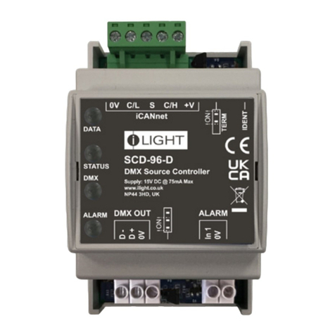
iLight SCD-96-D User manual

iLight

iLight SCD-96-D User manual

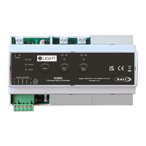
iLight SCMD2 User manual

iLight

iLight SCMD2 User manual

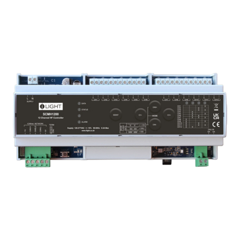
iLight SCMH1200 User manual

iLight

iLight SCMH1200 User manual

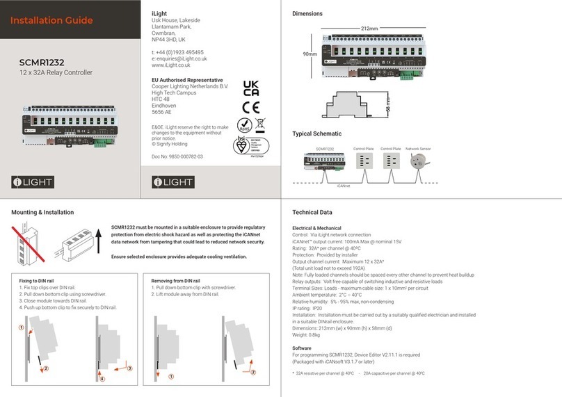
iLight SCMR1232 User manual

iLight

iLight SCMR1232 User manual

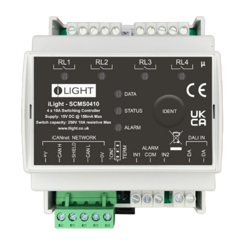
iLight SCMS0410 User manual

iLight

iLight SCMS0410 User manual

Popular Controllers manuals by other brands

Evco RICS 4.30 user manual

Evco

Evco RICS 4.30 user manual

WebDT WebDT 133 manual

WebDT

WebDT WebDT 133 manual

Sentera STR-4 series Mounting and operating instructions

Sentera

Sentera STR-4 series Mounting and operating instructions

Geco G-202-P05 Installation, operating and maintenance manual

Geco

Geco G-202-P05 Installation, operating and maintenance manual

AUMA SAEx 07.2 Operation manual

AUMA

AUMA SAEx 07.2 Operation manual

Roger CPR32-NET user manual

Roger

Roger CPR32-NET user manual

STORK TRONIC ST710-KPLVR.112S Wiring diagram

STORK TRONIC

STORK TRONIC ST710-KPLVR.112S Wiring diagram

SOMFY animeo IB + 1860085 installation guide

SOMFY

SOMFY animeo IB + 1860085 installation guide

Oldham MX 43 user manual

Oldham

Oldham MX 43 user manual

phytron MCC-1 manual

phytron

phytron MCC-1 manual

Satel ACU-280 manual

Satel

Satel ACU-280 manual

Selmo Thesis Plus manual

Selmo

Selmo Thesis Plus manual

BIFFI ALGAS-QA Series Instruction and operation manual

BIFFI

BIFFI ALGAS-QA Series Instruction and operation manual

POLA HP35 Handbook

POLA

POLA HP35 Handbook

Pentair INTELLIVALVE Installation and user guide

Pentair

Pentair INTELLIVALVE Installation and user guide

Timewave PK-232 MBX operating manual

Timewave

Timewave PK-232 MBX operating manual

ETC ArcSystem Pro D4 Series installation guide

ETC

ETC ArcSystem Pro D4 Series installation guide

Dungs VPM-LC Operation and assembly instructions

Dungs

Dungs VPM-LC Operation and assembly instructions

manuals.online logo
manuals.online logoBrands
  • About & Mission
  • Contact us
  • Privacy Policy
  • Terms and Conditions

Copyright 2025 Manuals.Online. All Rights Reserved.