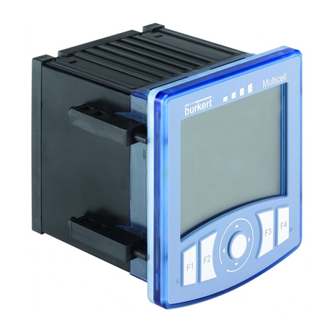
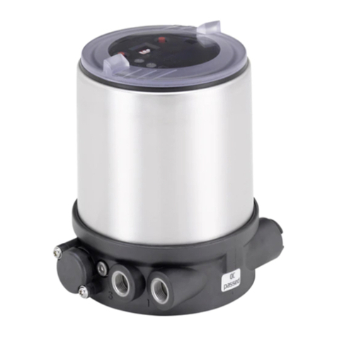
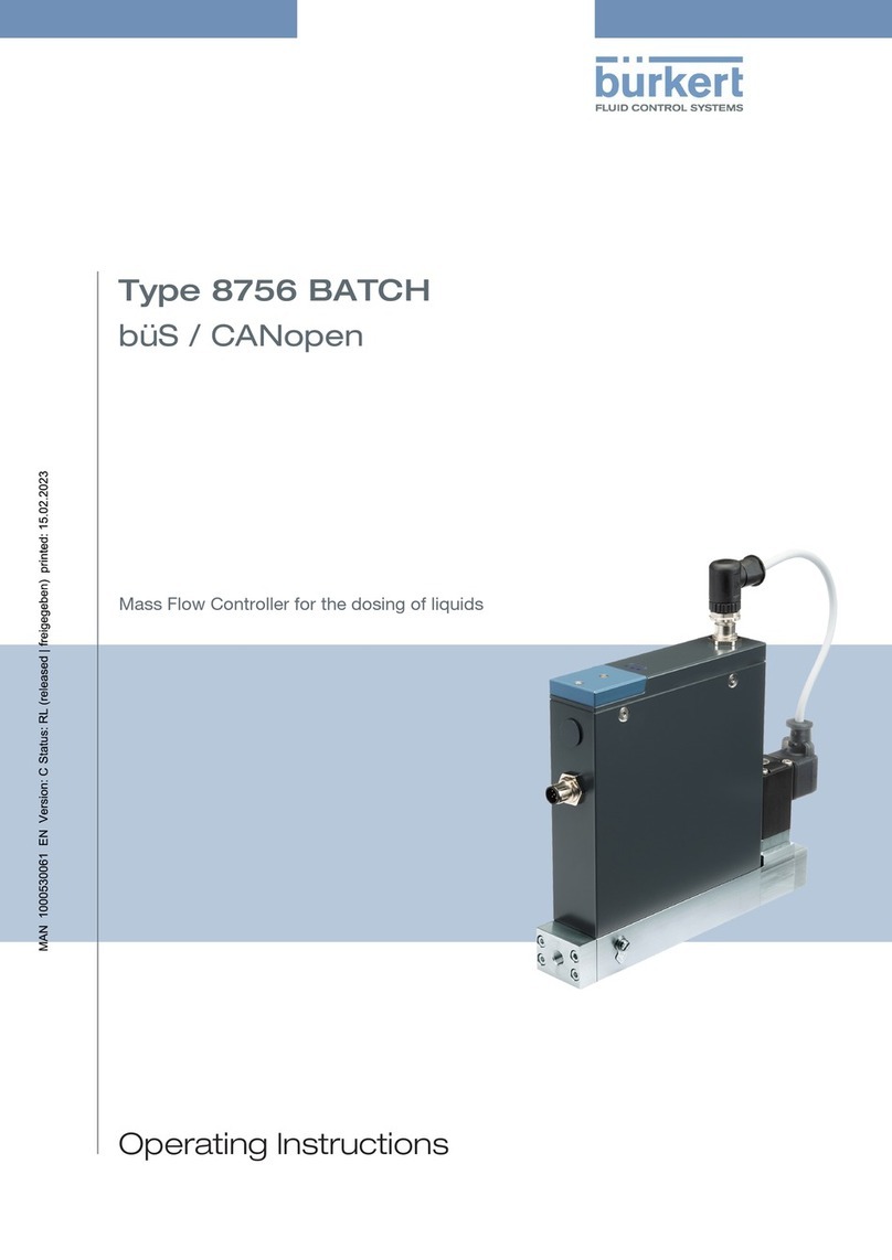
Burkert 8039 User manual

Instruction Manual
© Bürkert 2000 Subject to technical change

ENGLISH
ENGLISH
1.1 Utilisation .....................................................................................................................................................................................................4
1.2 Precautions at installation and commissioning ............................................................................................................5
1.3 Conformity to standards ..................................................................................................................................................................5
2.1 Design.........................................................................................................................................................................................................6
2.2 Measuring principle .........................................................................................................................................................................6
2.3 Order codes of electronic modules SE39 .....................................................................................................................7
2.4 Order codes of accessory ..........................................................................................................................................................7
4.1 General recommendations .....................................................................................................................................................12
4.2 Mounting on the pipe ..................................................................................................................................................................12
4.3 Electrical connection ...................................................................................................................................................................13
4.3.1 Cable plugs ...........................................................................................................................................................................13
4.3.2 Version with NPN transistor output via EN 175301-803 connector ...................................14
4.3.3 Version with PNP transistor output via EN 175301-803 connector ...................................14
4.3.4 Version with both NPN and PNP transistor outputs via M12 connector ...........................15

ENGLISH
ENGLISH
4.3.5 Version with PNP transistor output via M12 connector ..................................................................16
4.3.6 Version with relay output ...........................................................................................................................................16
4.3.7 Version with relay and frequency outputs ....................................................................................................17
5.1 General recommendations .....................................................................................................................................................18
5.2 Functionalities ...................................................................................................................................................................................18
5.3 Programming keys ........................................................................................................................................................................19
5.4 Default Configuration ..................................................................................................................................................................19
5.5 Normal Mode .....................................................................................................................................................................................20
5.6 Possible switching modes of the 8039 .......................................................................................................................21
5.7 Calibration Mode .............................................................................................................................................................................22
5.8 Simulation Mode .............................................................................................................................................................................25
6.1 Cleaning .................................................................................................................................................................................................26
6.2 Error messages ................................................................................................................................................................................26
6.3 When a problem occurs ............................................................................................................................................................27
7.1 Connection examples with a 8039..................................................................................................................................28
7.2 Description of the label of controller 8039...............................................................................................................31
7.3 Flow rate-velocity-DN diagrams .........................................................................................................................................32
ENGLISH
ENGLISH
.
The controller 8039 has only been designed to measure the flow rate of
liquids that let through the infrareds.
There will be no manufacturer warranty for damages caused by unexpec-
ted handling or wrong usage of the device. The warranty on the device
becomes invalid if any modification or change is made on the device.

ENGLISH
ENGLISH
- When the device is powered and the cover is open, protection against
electric shocks is not ensured.
- Always ensure the materials in contact with the medium to measure are
chemically compatible with this medium.
- To clean the device, only use chemically compatible products.
- Always protect the device from electromagnetic perturbations, ultravio-
let radiations and, when installed outside, from the effects of climatic
conditions.
EMC: EN 50 081-1, 50 082-2
Security: EN 61 010-1
Vibration: EN 60068-2-6
Shock: EN 60068-2-27

ENGLISH
ENGLISH
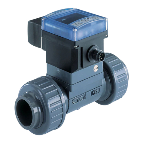
The flow rate controller 8039 is made up of an electronic module SE39
and a fitting S039 with integrated paddle-wheel. It may switch a solenoid
valve, activate an alarm or establish a control loop.
Furthermore, the version with a frequency output makes it possible to
transmit the paddle-wheel rotation speed (2 pulses/paddle-wheel turn)
directly to a PLC.
The switching point can be adjusted by means of the three keys located
under the display.
The electrical connection is carried out via an EN175301-803 connector
and/or a steerable M12 multipin connector.
The controller 8039 detects the rotation of the S039 fitting paddle-wheel.
The latter produces pulses whose frequency is proportional to the flow
rate (f = K.Q, where f is the frequency in Hz, K the K factor specific to
each fitting in pulses/l and Q the flow rate in l/s).
S039
SE39

ENGLISH
ENGLISH
5-pin M12 cable plug, to be wired 917116
5-pin M12 cable plug, moulded on a shielded cable (2 m) 438680
EN175301-803 cable plug (type 2508) with cable gland 438811
EN175301-803 cable plug (type 2509) with NPT 1/2'' reduction 162673
12-30 VDC NPN EN 175301-803 connector 440378
12-30 VDC PNP EN 175301-803 connector 440379
12-30 VDC PNP M12 connector 449556
12-30 VDC NPN and PNP M12 connector 440377
12-30 VDC Relay EN 175301-803 and M12 connectors 440382
12-30 VDC Relay and frequency EN 175301-803 and M12 connectors 447806

ENGLISH
ENGLISH
Pipe diameter DN6 to DN50 (1/4’’ to 2’’); determine the appropriate diameter using the
flow rate-velocity-DN diagrams (see Annex)
Fluid temperature max. 100 °C
Fluid pressure depends on the S039 fitting (see the corresponding fitting manual)
Fluid viscosity max. 300 cSt
Rate of solid particles max. 1%
Measuring range 0,3 m/s to 10 m/s (1.0 to 32 fps), 0.3 m/s (1.0 fps) corrresponds to a flow rate of 0,5 l/min
(0.2 gpm) in a DN6 (1/4’’) fitting.
Accuracy ±1 % of the full scale*, with calibration on site or using the teach-in function
± (1 % of the full scale* + 3% of the measured value), with standard K factor
Linearity ± 0.5 % of the full scale*
Repeatability 0.4% of the measured value
Measuring element paddle-wheel of the S039 fitting
Protection rating (housing) IP 65, cable plugs being plugged-in and tightened
* Full scale = 10 m/s
Installation class
(overvoltage class) 2
Insulating strength 2300 VAC
Power supply 12-30 VDC
Current consumption
Version with PNP output max.750 mA + consumption of the load, if the PNP output is connected
max. 50 mA + consumption of the load, if the PNP output is not connected
Version with relay output max. 80 mA, without load

ENGLISH
ENGLISH
Protection against
polarity reversal yes
Transistor output NPN and/or PNP, open collector, max. 700 mA, NPN output: 0,2-30 VDC and PNP output:
supply voltage (see example in the Annex)
Relay output 250 VAC, max. 3 A or 30 VDC, max. 3 A; programmable
Frequency output NPN transistor, open collector, max. 700 mA, 0,2-30 VDC, not programmable
Protection against
short-circuits yes for the transistor output
Type of cable recommended shielded, wire section between 0.14 and 0.5 mm2
NPN version EN 175301-803 cable plug (supplied)**
PNP version EN 175301-803- (supplied)** or 5-pin M12 (not supplied) cable plug
NPN/PNP version 5-pin M12 cable plug (not supplied)
Relay (+ frequency) version EN 175301-803 (supplied)** and 5-pin M12 (not supplied) cable plugs
** EaseOn with cable plug type 2511 on request
Housing polycarbonate, fiber glass reinforced
Front plate polyester and polycarbonate
Fitting S039 brass
Sensor holder / paddle-wheel PVDF
Fitting axis / bearings ceramic
O-rings FKM standard (EPDM as an option)
Ambient temperature 0 to +60 °C
Relative humidity < 80%, non condensated

ENGLISH
ENGLISH
Fluid velocity [m/s]
Max. error [%]
with the standard K factor (without calibration on site)
Typical Bürkert curve
with site calibration using the teach-in feature
These values have been determined in the following reference conditions: fluid = water, water
and ambient temperatures = 20 °C, min. upwards and downwards distances respected,
appropriate pipe dimensions.
1 9
2 3 4 5 6 7 8 10
4
8
20
-4
-8
-12
-16
-20
16
12

ENGLISH
ENGLISH
76
22
54
EN 175301-803
30
50
M12
SW 22
5440
H
06 80
08 80
15 85
20 82
25 83
32 86
40 90
50 96

ENGLISH
ENGLISH
- Always check the chemical compatibility of the materials the controller
is made of with the products it may be in contact with, for instance:
alcohols, strong or concentrated acids, aldehydes, bases, esters,
aliphatics, aromatics, ketones, aromatics or halogenated hydrocarbons,
oxidizing agents and chlorinated products.
- Avoid installing the controller near industrial lighting which may disturb
the optical sensor (mercury halide lamps for example).
For more information, please contact your Bürkert sales office.
The controller 8039 includes an S039 fitting for installation on a pipe.
Install the 8039 on the pipe so that the arrow on the housing indicates
the direction of the flow.
SE39
S039
1
2
3

ENGLISH
ENGLISH
1 2
Always ensure the power supply is switched off before working on the
device. All the cable plugs must be plugged out. Use:
- a shielded cable with an operating temperature > +80 °C.
- a high quality voltage supply (filtered and regulated).
- Loosen threaded ring [1]
- Remove part [2] from the connector.
- Wire according to pin assignment (see 4.3.4,
4.3.5, 4.3.6 or 4.3.7)
4
3
1
5
2
- To open the plug, unfasten screw [1].
- Remove part [3] from part [2].
- Unscrew cable gland [5].
- Insert cable into part [2] via cable gland.
- Wire part [3] (see 4.3.2, 4.3.3, 4.3.6 or 4.3.7).
- Replace part [3] into part [2], by 90°-steps.
- Tighten cable gland [5]. Place gasket [4]
between the cable plug and the fixed connector of the controller
and plug the 2508 onto the fixed connector.
- Tighten screw [1] to ensure tightness and correct electrical
contact.

ENGLISH
ENGLISH
NPN
0 V
V+ V+
IN
0 V
(*)
1
32
Sensor Receiver
Load
V+
(12-30 VDC)
NPN transistor output
0 V DC
NPN
output
V+
(12-30 VDC)
PNP transistor output
0 V DC
Sensor Receiver
Load
PNP
output
(*)
(*)
PNP
0 V
V+ V+
IN
0 V
(*)
1
32

ENGLISH
ENGLISH
PNP
0 V
V+ V+
IN
0 V
(*)
Sensor Receiver
Load
PNP
output
PNP transistor output
NPN transistor output
(*) Functional earth
(*)
Sensor Receiver
Load
NPN
output
NPN
0 V
V+ V+
IN
0 V
(*)
4
5
3
12
0 VDC
V+
(12-30 VDC)
1 brown
2 white
3 blue
4 black
5 grey
The controller is fitted
with a steerable M12 fixed
connector:
Unfasten counternut. Turn the
fixed connector to the right
position, but by max. 360° to
avoid twisting of the cables
inside the housing. Fasten
counternut using the appro-
priate tool while maintening
the fixed connector in the
right position.

ENGLISH
ENGLISH
1
3
2
4
5
3
12
0 VDC
V+
(12-30 VDC)
Sensor Receiver
Load
PNP
output
PNP transistor output
Not connected
Common
Not connected
Normally Closed
Normally Open
Not connected
Not connected
(*)
(*)
PNP
0 V
V+ V+
IN
0 V
(*)
4
5
3
12
0 VDC
V+
(12-30 VDC)
1 brown
2 white
3 blue
4 black
5 grey
The controller is fitted with a steerable M12 fixed
connector:
Unfasten counternut. Turn the fixed connector to the
right position, but by max. 360° to avoid twisting of the
cables inside the housing. Fasten counternut using the
appropriate tool while maintening the fixed connector in
the right position.

ENGLISH
ENGLISH
NPN
0 V
V+ V+
IN
0 V
(*)
Sensor Receiver
Load
The controller is fitted with a steerable M12 fixed connector:
Unfasten counternut. Turn the fixed connector to the right position, but by max. 360° to avoid
twisting of the cables inside the housing. Fasten counternut using the appropriate tool while
maintening the fixed connector in the right position.
When the voltage at the relay terminals is higher than 24 V and the cable
plugs are not correctly plugged-in and tightened, there is a risk to elec-
trocute yourself.
Always check all the cable plugs before powering the device to ensure
the good operating of the device.
Common
Not connected
Normally Closed
Normally Open
Frequency
Not connected
(*)
(*) Functional earth
Freq.
1
3
2
4
5
3
12
0 VDC
V+
(12-30 VDC)

ENGLISH
ENGLISH
Keep in mind that the process may be influenced by all the parameter
settings you make. Fill-in the table on page 24 with your settings of the
controller.
Frequency output cannot be programmed.
The device has three operating modes :
Display of the measured flow rate and the switching thresholds pro-
grammed. From the Normal mode, you can access the Calibration and
Simulation modes.
Access to the programming of all the parameters (unit, K-factor, calibra-
tion through the „Teach-in“ feature, output, filter, bargraph). From the
Calibration Mode, you can go back to the Normal Mode.
Entering a theoretical flow rate value to test the configuration program-
med in the Calibration Mode. From the Simulation Mode, you can go back
to the Normal Mode.

ENGLISH
ENGLISH
To display the measured value and the
configuration (8 characters:
4 numeric et 4 alphanumeric charact.)
Modifies the displayed value (0…9) ;
To go to the previous function.
To select the character;
To go to the next function.
To validate a function;
To validate the entered data.
To indicate the status of the
switching output (red LED)
At the first powering up, the configuration of the controller 8039 is as follows:
Flow rate unit: l/s
K factor 1
Output: hysteresis, inverted
OLO: 0
OHI: 0
DEL: 0 s
filtre: 2
BGLO: 0
BGHI: 0
EXT No (feature not used)

ENGLISH
ENGLISH
+
> 5 s
+
> 5 s
3
1
+ +
> 5 s
ENTER
ENTER
0......9
0......9
ENTER
0......9
2
00.00
L/S
20.00
O HI
10.00
O LO
the measured
flow rate.
the high threshold
value (O HI).
to the previous
function.
the low threshold
value (O LO).
the next function.
the measured flow
rate.
Table of contents
Languages:
Other Burkert Controllers manuals

Burkert
Burkert eCONTROL 8611 User manual

Burkert
Burkert 0911 User manual

Burkert
Burkert 3005 User manual

Burkert
Burkert Type 3003 User manual

Burkert
Burkert 3004 User manual

Burkert
Burkert 8750 User manual

Burkert
Burkert 8025 Series User manual

Burkert
Burkert 8691 REV.3 User manual

Burkert
Burkert 8681 User manual

Burkert
Burkert 3010 User manual

Burkert
Burkert 8691 User manual

Burkert
Burkert 8025 Series User manual

Burkert
Burkert 1094 Standard User manual

Burkert
Burkert FreeLINE 8645 User manual

Burkert
Burkert 8025 Series User manual

Burkert
Burkert 8718 User manual

Burkert
Burkert 8605 Series User manual

Burkert
Burkert 1094 EV User manual

Burkert
Burkert 8032 User manual

Burkert
Burkert 8750 User manual