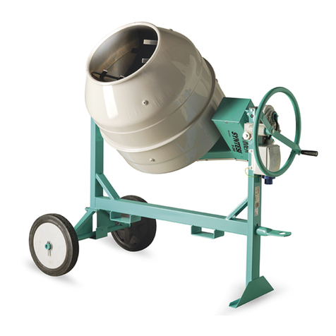
Imer Group IMR750 Guide

OPERATING, MAINTENANCE, SPARE PARTS MANUAL FOR CONCRETE MIXER:
LIBRETTO DI USO E MANUTENZIONE PER BETONIERA:
Modelo: IMR750
IMER Latinoamerica y El Caribe, Inc.
9383 NW 13Th St - Miami Fl 33172
Phone: (305) 593 9890 – Fax: (305) 675 2260
Julio 2007

2/27
1 GARANZIA / GUARANTEE / GARANTIE……………………………………………………………………………………..………... 4
2 LIVELLO EMISSIONE SONORA / NOISE EMISSION STANDAR / NIVEAU D’EMISSION SONORE………………………….. 4
3 DATI TECNICI / THECNICAL DATA / DONNE TECNIQUE………………………………………………………….……………….4
4 SICUREZZA OPERATIVA / OPERATING SAFETY / SICURITE OPERATIONELLE…………………………………………..….5
5 SICUREZZAELETTRICA / ELECTRONICAL SAFETY / SECURITE ELECTRIQUE…………………………………..………….5
6 SICUREZZA MECCANICA / MECHANICAL SAFETY / SECURITE MEQUANIQUE………………………………….………… 5
7 TRASPORTABILITA’ / TRANSPORT / TRASPORT……………………………………...……………………………………………..5
8 INSTALLAZIONE / INSTALLATION / INSTALLATION……………………………………………………………………………….5
9 ALLACCIAMENTO ELETTRICO / ELECTRICAL CONNECTION / BRANCHEMENT ELECTRIQUE………………………… 5
10 MESSA IN MARCIA / START UP / MISE EN MARCHE ……………………………………………………………………………….. 6
11 MODALITA’ D’USO / USE / MODALITE D’UTILISATION……………………………………………………………………………. 6
12 EMERGENZA STOP / EMERGENCY STOP / URGENCE STOP………………………………………………………………………. 7
13 MANUTENZIONE / MAINTENANCE / ENTRETIEN…………………………………………………………………………………….7
14 INDICAZIONE PULIZIA/CLEANING INDICATION/ INDICATION DE NETTOYAGE………………..……………………….… 8
15 DIC. DI STABILITA’ AL RIBALTAMENTO / TILTING STABILITY DEC. / DEC. DE STABILITE AU BASCULEMENT…...8
16 INDIVIDUAZIONE GUASTI / TROUBLESHOOTING / INCONVENIENT……………………………………………………………9
17 PEZZI DI RICAMBIO / SPARE PARTS / PIECES DE RECHANGE…………………………………………………………………...16
18 SCHEMA ELETTRICO / WIRING DIAGRAM / SCHEMA ELECTRIQUES…………………………………………………………24

3/27
Ai fini della sicurezza è indispensabile leggere questo manuale con particolare
attenzione ai punti segnati con questo simbolo.
In order to be able to work in complete safety , the following instruction must be read carefully
with special attention to warning with this symbol
Questo manuale deve essere custodito vicino alla macchina o nei pressi da parte del
capocantiere o da chi ne fa le veci. Il manuale è da considerarsi parte della macchina e
deve essere conservato per futuri riferimenti fino alla distruzione della macchina
stessa.
This operating and maintenance manual must kept on site by the site foreman or the person
responsible for the site. The manual should be considered as being an integral part of the
machine, and must be kept for the future reference until the machine itself is disposed of.
Affinché sia garantita la sicurezza dell’operatore ed una lunga durata della macchina
devono essere rispettate le istruzioni e le norme del manuale unitariamente a quanto
scritto. Devono essere inoltre rispettate le norme di sicurezza e prevenzioni infortuni
sul lavoro secondo la legislazione vigente.
In order that the safety of the operator, safe working and long life of the equipment can all be
guaranteed, the instruction of the manual must be followed together with safety standards
and health and safety at works laws currently in force .
È vietato apportare modifiche di qualsiasi natura alla struttura metallica o impiantistica
della macchina.
declina ogni responsabilità in caso di non osservanza delle leggi che regolano l’uso di
tali dispositivi, in particolare l’uso improprio, difetti di alimentazione, modifiche non
autorizzate, inosservanza totale o parziale delle istruzioni contenute in questo
manuale.
It is strictly forbidden to carry out form of modification to the structure or working parts of the
machine.
Decline any responsibility in the case of non-compliance with laws and standards governing
the use of this equipment. In particular: improper use, defective power supply, lack of
maintenance, unauthorized modifications, partial or total inobservance of instructions
contained in this manual.

4/27
1 GUARANTEE
The producer guarantees its own machines for a period of 365 days from the purchase date
and no more than 15 month after the transport bill date. Guarantee has to be limited to the
substitution of the only part that according the producer is defective. Every other kind of
responsibility and obligation for other cost, damage, lost, direct or indirect, deriving from the
use of the machine is excluded. Reparation has to be consider as ex work. Every kind of
cost for transport at the buyer charge. Guarantee finish after the period overwrite and
when one of these hypothesis happened:
•non maintenance or wrong maintenance;
•tampering of seal;
•use of unauthorized lubricating;
•reparation made by unauthorized operator or with unoriginal spare parts;
•push or other accidental happening;
•non receiving of guarantee card with all purchase information and reseller validation;
Moreover guarantee does not include damaged caused by normal wear and electric parts.
Motor guarantee is given in the limit It is given from the producer house.
2 NOISE EMISSION LEVEL (Rif. the same machine)
Equivalent weighed continuous sound pressure “A” in the work place
FG2-75ME Elect. Motor < 80 db
FG2-75MD Elect. Motor < 85 db
3 TECHNICAL DATA TECHNICAL DATA
Drum ca
p
acit
y
Lt 750
Mix ca
p
acit
y
Lt 500
Water tank ca
p
acit
y
Lt 80
Drum diameters mm 1300
Drum rot. direction for mixin
g
A
NTIORARIO
Drum rot.direction
(
dischar
g
in
g)
ORARIO
N. Drum r
p
m
g
iri/min 22
Concrete hour
p
roduction Mc/h 16
Overall dimension
(
raised ho
pp
er
)
LUxLAxH 3000x2100x3000
Machine wei
g
ht FG2..ME K
g
1250
Machine wei
g
ht FG2..MECP K
g
1334
Machine wei
g
ht FG2..MD K
g
1360
Motor ratin
g
Electric .Motor K
w
7,5
Motor ratin
g
Disel Motor K
w
12.,0
A
bsorbed curr.
A
7,2
Volta
g
e V 380
Fre
q
uenc
y
Hz 50
Scraping Shovel
Motor rating E.M Kw 1,85
Absorbed current A 4,6
Traction speed m/sec 0,72
Traction capacity Kg 257
Drum rpm n/min 92
Stell cable m 12

5/27
4 SAFETY INSTRUCTIONS
BEFORE USING MACHINE ENSURE ALL SAFETY DEVICES ARE FITTED
Keep all parts of body clear of mixing drum during operation
Power supply line must be installed where they will not be subject to damage. Do not position
concrete mixer over power supply cable.
Avoid any contact of plugs with water. Only use plug and sockets with protection against
water spay (IP 55)
Do not use electrical lines that are undersize makeshift or without the earth wire.
Repairs to the electrical installation must be only be carried out by qualified personnel.
DICONNECT MACHINE FROM POWER SUPPLY AND STOP MOTOR BEFORE
STARTING ANY MAINTENANCE OPERATIONS OR REPAIRS IT MUST NEVER BE
USED IN EXPLOSITION RISK AREAS OR FIRES OR IN UNDERGROUND EXCAVATION.
5 ELECTRICAL SAFETIES
The machine is protected again the automatic restart after the interruption and the restart of
the electric alimentation. It is protected against water spray (IP –55). It is fitted with protection
devices against voltage droops or overloading.
6 MECHANICAL SAFETIES
All dangerous areas on the concrete mixer have protective casing which must be kept in
perfect condition, e.g. motor housing, ring gear guard, pinion guard and drive belt guard.
7 TRANSPORT
As regard road transport of the machine in not allowed. For transport on the building site with
lifting equipment (host or similar) attach lifting hook to fixture provided. Move mixer manually
by means of hand well.
8 INSTALLATION
The machine has to be placed on flat and solid ground.
•Take away the wheels and put the mixer on a plane using the 4 feet (5° max accepted
incline).
•Protect the hubs to prevent rust and lime’s deposit.
•Anchor the mixer to the ground using the 4 brackets (Tee of 20 UNI 5681).
9 ELECTRICAL CONNECTIONS – MIXER ELECTRONIC MOTOR
The connection with the builder yards electronic plant must be make by professional electric-
man. For the electric connection the machine is equipped with tap derivation with earthling
tap. It is also provided with a juncture for a different heart connection. Note mains voltage
and cable diameter specification
1. Absolutely avoid occasional or temporary connection not in conformity with the regulations.
2. Cheek to see if the tension is suitable for the machine.

6/27
3. Make the connection using a three-pole cable (3 phase + earth) of proper section.
4. The electric cable must be connected downward to the terminal board inside the electric
panel and upward to a distribution board with: switch, bloc-tap, fuses.
5. Make the earth connection using the electric line and the special screw.
6. Check if the rotation of the drum, of the cable-drum and of the scraping-shovel is the one
shown by the signaling otherwise switch the wires in the electric panel.
MIXER WITH INTERNAL COMBUSTION MOTOR
Does not need any other contrivance.
10 START UP
After having connected and locked the plug, turn on the mixer with the green start push
button. The electronic panel consists of an a start push button and a mush-room-head push-
button. The plug is situated belong. The start button has the function of leaving the coil of
minimum tension. To reset the switch and restart the machine after an unexpected power cut,
press the switch. When there is a stop of the machine at first tour the Mush-room-head
pushbutton then push the start button again.
11 USE
•Only the operator can stay near the machine during the machine work
•Do not use the machine in resort where there is fire dangerous. can spark could cause
fires or explosions.
•Before leaving the machine tour the motor off.
•During machine transport make attention the motor is turned off.
•Verify that the voltage correspond of the one indicated on the plate.
•Check that if the electronic line has protection upstream
•Check that the drum rotation is anti-clockwise.(drum view).
•Connect the machine to the electric line. Turn on the machine.
•Absolutely avoid occasional or temporary connection not in conformity with the
regulations.
•Cheek to see if the tension is suitable for the machine.
•Lower the hopper pushing the lever in the direction shown by the plate after having
removed the safety-bolt.
•Load the material in the hopper. (if you must use scraping-shovel, make sure that the draw
steel cable does not exceed the front feet)
•Let flow the necessary water in the drum.
•Let the drum rotate in the “mix” direction.**
•Raise the hopper pushing the distributor level, stopping a few times to discharge the
material and add more water.
•Lower the hopper again and wait as long as requested from the mix, adding more water if
needed. To discharge the mix stop the rotation and after a few second rotate the drum in
the direction of “discharge”.**
•**For such operations push the button in the electronic box or the reversing gear level for
the concrete mixer with internal-combustion engine.

7/27
IT’S FORBIDDEN THE ACCES TO THE DRUM WHILE IT’S RUNNING
AVOID TO TURN ON THE MACHINE WHEN IT IS FULLY LOADED
12 EMERGENCY-STOPS
In case of an emergency with an electronic motor, immediately press the switch or disconnect
the power supply.
The electric motor is protected from the thermal overloads. If it overheats the mixer will stop.
Allow the motor to cool down before restarting. For turning the machine on pull the
mushroom-head- -push-button and push the start button.
13 MAINTENANCE
WARNING!! BEFORE EVERY KIND OF MAINTEINANCE, ALWAYS SWITCH OFF THE
MOTOR AND DISCONNECT THE POWER SUPPLY
GENERAL TIPS
•Grease periodically: crown gear, rollers, hopper’s pin.
•Check constantly the tension pf the belts to avoid slipping.
•Maintain the right play between the crown-gear and rollers, using the special register
positioned on the top of the mixer.
•Check periodically the oil level in the scraping-shovel reducer (SAE 60), in the Hydraulic
reducer (SAE 90) and where It is scheduled. in the piston engine, in the reversing gear
(SAE 50).
•When required adjust the friction clutches of the reversing-gear doing as follows:
•Take away the upper door, where is located the oil plug in.
•Release the 2 registering rings, loosening the threaded dowel above them.
•Turn the rings clockwise to increase the transmission power, or anti clockwise to reduce it;
•Close again the threaded dowels and operate in the opposite way.
HYDRAULIC SYSTEM
•Change the oil after 200 working hours and afterwards every 500 working hours.
•After every change of oil disassemble the filter and clean it with diesel oil or petrol.
•Check that the air aspiration hole on the oil tank plug is not stopped.
•The oil must be right one for oleo dynamic drive; prescribed viscosity is of 3/6 Engler at
50° C temperature.
•The hydraulic system is adjusted to a working pressure of 125 Kg/cm2. Installing a
pressure gauge on the oil outlet, distributor-jack, and pushing on the distributor lever to
raise the loaded hopper, you get a different pressure , screw the distributor cap (pos. 13
TAV.05) and adjust the screw with key: tight it if the pressure is lower or loosen it if the
pressure is higher. If you don’t have a pressure-gauge do as above described, loosening
the screw longer because that could causes an executive pressure. Leave the lever and
screw the cap tightly.

8/27
WE RECOMANDED MOREOVER:
•Do lubrication and maintenance when the machine is out.
•Replace damaged part with others having the same characteristics (you can request the to
our reseller)
•Periodic and scrupulous control of every par.
•Keep the danger and warming signaling always legible.
•Empty the drum every time a mixing is finished and wash it every evening.
•Check if the walls of the drum are clean.
SERVICE
•We recommend to use original spare parts. To request spare parts It must be indicated:
•Tilting-mixer type an matriculation-number
•Number of the drawing TAV
•Reference number and the code indicated in every denomination
14 CLEANING INSTRUCTION
After each daily work session or before long period of inactivity, the mixer must be cleaned
thoroughly both inside and outside
Before cleaning the mixer, always switch off the motor and disconnected electric plug. (Even
when using brooms, rags, scraper, etc.). Do not start the mixer while carrying out cleaning
operations. When using a hose for cleaning, do not direct the spray into the plug-switch unit.
The door of the motor casing must be closed.
If the protection guards are removed for cleaning, always replace them correctly at the end of
the cleaning operation.
Clean the outside of the mixer with a brush and water. Scrape off any cement or concrete
deposits.
There should not be any deposits of cement or concrete inside the drum or on the teeth of the
transmission gear. The inside of the drum can be cleaned better if, at the end of the work
session or before prolonged period of inactivity, the drum is rotated with a few shoved-fulls of
gravel and water. This will prevent any residue of cement or concrete in the drum and on the
mixing paddles from hardening.
The mixing drum must not be struck with hard objects such as hammers or shovels, etc. A
dented drum will reduce the mixing effects and make cleaning more difficult.
Repairs
Repairs to system must be carried out exclusively by specialist staff. If the protection guards
are removed during repair operation, they must be correctly replaced when repairs are
complete.
15 STABILITY DECLARATIONS
concrete mixer are conformed with the project completed with tilting stability verify.

9/27
16 TROUBLESHOOTTING - WARNING!!
All maintenance work must be carried out after the machine has been stopped at the switch
and unplugged from the power supply.
INCONVENIENT CAUSES REMEDES
The motor does not run
when the switch is
pressed.
No power in the supply line-. -Check the line.
-.The electric plug and
socket are not connect
properly.
- Make a proper connection.
-A wire has become
disconnected on the
terminal board.
- Remake the connection.
-The fuse inside is broken -Replace the fuse
The switch is faulty. - Replace the switch..
-The thermal protection
device has been tripped. - Wait a few minutes and try
again
During mixing the mixer
drum rpm decreases Belts are slack and are
slipping.- Tension the belts-
-The upstream protection is
opened -Make the machine check
by an electrician

10/27
1 GARANZIA
La casa costruttrice garantisce le proprie macchine per un periodo di 365 giorni a partire dalla
data di acquisto. E comunque non oltre i 15 mesi dalla data del D.D.T. dai ns. stabilimenti. La
garanzia deve intendersi limitata alla sola sostituzione delle parti che, ad insindacabile
giudizio della direzione della casa costruttrice, o di chi per essa autorizzato, risultassero
difettose. Ogni qualsiasi altra responsabilità e/o obbligazione per altre spese, danni e perdite,
dirette o indirette, derivanti dall’uso della macchina totale o parziale è esclusa. La riparazione
in garanzia è intesa franco ns. sede o franco ns. officina autorizzata a svolgere riparazioni.
Ogni spesa di trasporto e/o imballo inerente alla riparazione stessa è a carico dell’acquirente.
La garanzia decade automaticamente trascorso il periodo sopra citato, oppure quando si
verifichi anche una sola delle seguenti ipotesi:
•mancata o errata manutenzione;
•manomissione degli appositi sigilli;
•uso di lubrificanti non idonei;
•riparazioni eseguite da personale non autorizzato e/o con ricambi non originali;
•urti, incendi o altri fatti accidentali;
•mancato ricevimento della cartolina di garanzia, riportante tutti i dati di acquisto, e
convalidata dal rivenditore.
La garanzia non è inoltre applicabile alle avarie derivanti dalla normale usura, ed alle parti
elettriche. La garanzia dei motori è concessa nei limiti cui la stessa è ottenibile dalla casa
costruttrice, dai costruttori dei componenti stessi.
2 LIVELLO EMISSIONE SONORA (rif. macchina identica)
Livello di pressione acustica continuo equivalente ponderato A nel posto di lavoro
Betoniere FG2-75ME Mot. Elettrico < 80 db (A)
Betoniere FG2-75MD Mot. Diesel < 85 db (A)
3 DATI TECNICI
MODELLO BETONIERA
Ca
p
acità vasca Lt 750
Ca
p
acità di im
p
asto Lt 500
Ca
p
acità serbatoio ac
q
ua Lt 80
Diametro vasca mm 1300
Direzione rotaz. vasca
A
NTIORARIO
Direzione rotaz.vasca svuotamento ORARIO
N°
g
iri vasca
g
iri/min 22
Produz. oraria cemento finito Mc/h 16
Misure d'in
g
ombro
(
benna sollevata
)
LUxLAxH 3000x2100x3000
Peso FG2C…ME K
g
1250
Peso FG2C…MECP K
g
1334
Peso FG2C…MD K
g
1360
Potenza motore rotazione elettrico K
w
7,5
Potenza motore rotazione diesel K
w
10,5
Corrente assorbita
A
7,2
Tensione V 380
Fre
q
uenza Hz 50

11/27
Pala raschiante
Potenza motore elett 380V/50Hz Kw 1,85
Corrente assorbita A 4,6
Velocità di trazione pala m/sec 0,72
N° giri tamburo Kg 257
Velocità di trazione m/sec 92
Lung. Cavo acciaio m 12
4 SICUREZZA OPERATIVA
PRIMA DI UTILIZZARE LA MACCHINA ACCERTARSI CHE SIA MUNITA DI TUTTI I
DISPOSITIVI DI PROTEZIONE
•Vietato introdurre parti del corpo all’interno della vasca di miscelazione.
•Le linee di alimentazione devono essere posate in modo tale da non poter essere
danneggiate. Non appoggiare mai la betoniera sopra il cavo di alimentazione stesso.
•L’allacciamento elettrico deve essere tale da impedire la penetrazione di acqua nei
connettori. Impiegare solo connettori ed attacchi muniti di protezione contro gli spruzzi
d’acqua (IP 55).
•Non utilizzare cavi inadeguati come sezione o privi della protezione di terra.
Le riparazioni degli impianti elettrici devono essere effettuate da personale specializzato.
SCONNETTERE LA MACCHINA PRIMA DI QUALSIASI RIPARAZIONE O
MANUTENZIONE.
NON DEVE ESSERE USATA IN AMBIENTI OVE ESISTA PERICOLO DI ESPLOSIONI,
INCENDIO O SCAVI SOTTERRANEI.
5 SICUREZZA ELETTRICA
La macchina è protetta contro il riavviamento automatico dopo l’interruzione e il ripristino
dell’alimentazione elettrica.E’ protetta contro gli spruzzi d’acqua (IP-55) ed dotata di
protezioni contro i sovraccarichi di minima tensione.
6 SICUREZZA MECCANICA
Nelle betoniere le parti pericolose sono protette mediante opportuni dispositivi, che devono
essere mantenuti in perfette condizioni, come per esempio il coperchio cabina motore, la
protezione del pignone di rotazione e la copertura della corona.
7 TRASPORTABILITA
Non è consentito il traino anche se lento. Per la movimentazione della macchina in cantiere
utilizzare l’apposita campanella, mentre per quello manuale utilizzare il timone in corredo.
8 INSTALLAZIONE
La macchina deve essere posata in piano su terreno consistente..
•Togliere le ruote e mettere in piano la betoniera servendosi dei quattro piedi (pendenza
max accettata 5°).
•Proteggere i mozzi per evitare la ruggine e i depositi di calce.
•Ancorare la betoniera a terra mediante 4 staffe (profilato a T di 20 UNI 5681)

12/27
9 BETONIERA CON MOTORE ELETTRICO - ALLACCIAMENTO ELETTRICO
RISPETTARE LA TENSIONE DI RETE ED IL DIAMETRO DEI CAVI!
La connessione all’impianto elettrico di cantiere deve essere eseguita da personale
qualificato elettricista. Per il collegamento elettrico la macchina è predisposta con derivazione
a spina munita di spinotto supplementare di terra. E’ predisposto anche un attacco per un’
eventuale esigenza di connessione di terra diversa.
1. Evitare assolutamente allacciamenti occasionali, provvisori e non conformi ai regolamenti.
2. Controllare che la tensione di linea sia idonea per la macchina.
3. Fare l’allacciamento usando cavo tribolare (3 fasi + terra) di adeguata sezione.
4. Il cavo elettrico deve essere collegato a valle alla morsettiera posta all’interno del quadro
elettrico ed a monte ad un quadro di distribuzione con. interruttore, prese di blocco,
fusibili.
5. Fare il collegamento di terra mediante linea elettrica e l’apposita vite.
6. Controllare che la rotazione della vasca e del tamburo avvolgicavo della pala raschiante
sia quella indicata dalle segnalazioni; altrimenti scambiare i fili del quadro.
BETONIERA A MOTORE A SCOPPIO
Non necessita altri accorgimenti
10 MESSA IN MARCIA - LAVORO
Dopo aver inserito la spina ed averla bloccata, accendere la betoniera mediante l’interruttore
(verde). Il quadro elettrico è composto da un interruttore di accensione e riavvio, da un fungo
di arresto stop di emergenza . Nella parte sottostante è situata la spina. L’interruttore esplica
la funzione di sgancio bobina di minima tensione. In caso di mancanza di rete è necessario
premere di nuovo il pulsante di avvio.Mentre nel caso di uno stop per riavviare la macchina,
prima si dovrà ruotare leggermente il fungo di arresto, quando questo è ritornato nella
posizione di uso premere di nuovo il pulsante di avvio.
11 MODALITÀ D'USO
•Non permettete che altre persone salvo l’operatore rimangano vicino alla macchina durante
il lavoro.
•Non usate la macchina in zone a pericolo di incendio. Eventuali scintille possono provocare
incendi o esplosioni.
•Spegnere sempre il motore prima di lasciare la macchina.
•Fate attenzione nel posizionare e trasportare la macchina a motore fermo.
•Verificare che la tensione di alimentazione sia corrispondente con quella riportata
sull'apposita targa.
•Assicurarsi che la linea elettrica sia provvista di una protezione differenziale a monte.
•Assicurarsi che la rotazione della vasca di miscelazione sia in senso antiorario (visto dalla
bocca di scarico).
•Collegare la macchina alla linea elettrica. Mettere in marcia la macchina.
•Abbassare la benna agendo sulla leva del distributore nel senso indicato nella targhetta,
dopo aver tolto il dispositivo di sicurezza.

13/27
•Caricare il materiale nella benna, dove è prevista usare la pala raschiante facendo
attenzione al cavo d’acciaio in tiraggio non superi mai i piedi anteriori
•Scaricare nella botte l’acqua necessaria.
•Far Rotare la botte nel senso di “impasto”**
•Far risalire la benna mediante la leva di distribuzione fermandosi alcune volte per scaricare
meglio il materiale e aggiungendo altra acqua.
•Abbassare nuovamente la benna e attendere il tempo necessario per l’impasto
aggiungendo altra acqua se occore.
•Per scaricare l’impasto interrompere la rotazione e dopo alcuni secondi far ruotare la botte
nel senso di “scarico”**
•** Per tali operazioni agire sul pulsante della cassetta elettrica o sulla leva dell’invertitore
per le Betoniere a motore a scoppio.
È VIETATO L'ACCESSO ALLA VASCA DI MISCELAZIONE IN FUNZIONE. EVITARE DI
METTERE IN MOTO LA MACCHINA A PIENO CARICO.
12 EMERGENZA STOP
In caso di emergenza premere l'interruttore o staccare la presa di corrente.
Il motore elettrico è protetto dai sovraccarichi termici, in caso di surriscaldamento si arresta.
Far raffreddare e avviare di nuovo. Per riavviare la macchina occorre tirare il fungo di
emergenza e poi premere il pulsante di avvio.
13 MANUTENZIONE
ATTENZIONE!! PRIMA DI QUALSIASI MANUTENZIONE OCCORRE SEMPRE
SPEGNERE LA BETONIERA E STACCARE LA SPINA DI ALIMENTAZIONE.
GENERALE
•Ingrassare periodicamente. la corona, i rulli il perno della benna.
•Controllare periodicamente la tensione delle cinghie onde evitare che slittino.
•Mantenere il giusto gioco fra corona e rulli agendo sull’apposito registro posto sulla parte
superiore della Betoniera.
•Controllare periodicamente il livelli dell’olio nel riduttore della pala raschiante (SAE 60), nel
riduttore idraulico (SAE 90) e dove previsto; nel motore a scoppio e nell’invertitore (SAE
50).
•All’occorrenza registrare le frizioni dell’invertitore procedendo nel seguente modo:
•Togliere la portella superiore dove è posizionato il tappo olio ;
•Sbloccare due anelli di registro, allentando il grano filettato sopra di essi;
•Girare gli anelli nel senso orario per aumentare la capacità di trasmissione, od in senso
antiorario per diminuirla;
•Serrare nuovamente i grani filettati e procedere in modo inverso.
IMPIANTO IDRAULICO
•Sostituire l’olio dopo le prime 200 ore di funzionamento e in seguito ogni 500 ore di lavoro.
•Ad ogni cambio d’olio, smontare il filtro e pulirlo con nafta e benzina.
•Controllare che non so otturi il foro di aspirazione aria sul tappo del serbatoio olio.

14/27
•L’olio deve essere adatto per comandi, oleodinamici, la vischiosità prescritta è del 3/6
Engler alla temperature di 50°.
•L’impianto idraulico viene tarato ad una pressione di esercizio di 125 Kg/cm2. Istallando
un ,manometro all’uscita olio, distributore martinetto, e agendo sulla leva del distributore-
martinetto, e agendo sulla leva del distributore per far salire la benna carica, se si
riscontrasse una pressione diversa, svitare il cappellotti del distributore (pos. 13 TAV.05)
ed agire con una chiave sulla vite; per stringerla se la pressione è inferiore o allentarla se
la pressione è maggiore. In mancanza di un manometro agire come sopra allentando la
vite, fatto ciò riavviare gradualmente finché la benna comincia a salire avendo cura di non
avvitare oltre perché si otterrebbe una pressione eccessiva. Lasciare la leva, riavviare il
cappellotto stringendo bene.
SI RACCOMANDA INOLTRE:
•Di eseguire le operazioni di lubrificazione e manutenzione a macchina spenta.
•La sostituzione dei pezzi avariati con altri aventi le stesse caratteristiche (possono essere
richiesti ai nostri rivenditori).
•Un controllo periodico e scrupoloso di tutte le parti.
•L’obbligo di mantenere sempre leggibili le segnalazioni di pericolo ed avvertimento.
•Svuotare la botte ad ogni mescolamento ultimato e lavarla ogni sera.
•Controllare la pulizia delle pareti della benna.
ASSISTENZA
Si raccomanda l’uso di pezzi di ricambio originali. Per la richiesta di pezzi di ricambio indicare:
•Tipo betoniera e sua matricola
•Numero di disegno TAV
Numero di riferimento e codice collocato in corrispondenza di ogni denominazione
14 INDICAZIONI PER LA PULIZIA
Prima di una lunga pausa di lavoro o al termine del lavoro quotidiano, la vasca di
miscelazione deve essere pulita a fondo all'interno ed all'esterno. Prima di procedere alla
pulizia manuale della betoniera (anche se effettuata con spazzole, stracci, raschietti ecc.)
occorre sempre spegnerla e staccare la spina dall'alloggiamento del motore.
Quando si esegue la pulizia manuale, non si deve mettere in funzione la betoniera.
Se la pulizia viene eseguita mediante getti d'acqua, non indirizzare questi ultimi direttamente
sul gruppo spina-interruttore. Pulire la betoniera all'esterno con una spazzola e acqua.
Raschiare le incrostazioni di calcestruzzo e malta.
All'interno della vasca non devono formarsi incrostazioni di calcestruzzo e malta.
L'interno della vasca si pulisce meglio se, prima di lunghe pause e/o al termine del lavoro, si
fa funzionare la betoniera con alcune palate di ghiaia ed acqua. In tal modo si impedisce
l'indurimento dei residui di calcestruzzo o malta nel tamburo e nelle pale di miscelazione.
La vasca di miscelazione non deve essere colpita con oggetti duri come martelli, pale ecc.
Una vasca di miscelazione ammaccata peggiora il procedimento di miscelazione ed è anche
più difficile da pulire

15/27
Riparazione
Le riparazioni degli impianti possono essere eseguite esclusivamente dal personale
specializzato. Se per eseguire riparazioni vengono rimosse le coperture di protezione, a fine
intervento devono essere rimontate correttamente.
15 DICHIARAZIONE DI STABILITA’ AL RIBALTAMENTO
le betoniere mod.. IMR750 sono conformi al progetto, completo di verifica di stabilità al
ribaltamento.
Il calcolo garantisce che il momento stabilizzante non è inferiore al doppio del massimo
momento ribaltante ipotizzabile nelle condizioni di esercizio specificate nel manuale d’uso e
manutenzione.
16 INDIVIDUAZIONE GUASTI
ATTENZIONE !!
Tutti gli interventi di manutenzione devono essere eseguiti dopo aver fermato la
macchina, agendo sull'interruttore, e staccando la presa di alimentazione
SINTOMO CAUSA POSSIBILE INTERVENTO
Dopo aver tirato il fungo di
emergenza e premuto
l’interruttore di avvio, il
motore non parte
- Non arriva tensione sulla
linea di alimentazione. -Controllare la linea.
- La presa e la spina
elettrica non sono ben
collegate.
- Ripristinare un corretto
collegamento.
- Un filo elettrico all'interno
della morsettiera motore è
staccato.
- - Collegare di nuovo.
- Il fusibile interno al quadro
non è integro - Sostituirlo.
- Il sistema
elettromeccanico è guasto. - Sostituirlo.
- La protezione termica ha
interrotto il circuito elettrico - Attendere qualche minuto
ed accendere il pulsante
avvio
Durante l’impasto
diminuiscono i numeri di
giri
- Le cinghie sono lente e
slittano. - Tensionare le cinghie
- È aperta la protezione
differenziale a monte. - Ripristinare se non si
ripristina, far controllare
l'impianto da un esperto
elettricista in quanto esiste
un guasto importante ai fini
della sicurezza.

16/27
PEZZI DI RICAMBIO
Pos. Codice Descrizione Description Descrition
1 FG200R175 Telaio Chassis Frame
2 FG200R275 Corona Vasca Couronne de la Cuve Drum's Crown-
g
ear
3 FG200R375 Vasca Cuve Drum
4 FG200R475 Carter Vasca Carter Cuve Cover Drum
5 FG200R575 Carter Vasca inferiore Carter cuve in
f
σrieure Cover lower drum
6 FG200R675 Bocchetta di carico Goulotte de char
g
ement Loadin
g
hole
7 FG200R775 Benna Ski
p
Ho
pp
e
r
8 FG200R875 Perno Benna Pivot Benne Ho
pp
er's
p
ivet
9 FG200R975 Martinetto VΣrin Jack
10 FG200R10 Valvola di blocco Sou
p
a
p
e de bloc Block valve
11 FG200R11 Serbatoio olio Rσservoir huile Oil tank
12 FG200R12 Carter serbatoio olio Carter
r
σservoir huile Oil tank cove
r
13 FG200R1375 Cassetta elettrica Ex
p
ort Boitie
r
Electric
p
anel box
14 FG200R1475 Motoriduttore -
p
ala Reducteur mouv.
p
elle Shovel's motion reduce
r
15 FG200R15 Carter motoriduttore
p
ala Carter reduc. mouv.
p
elle Shovel's motion red. cove
r
16 FG200R16 Su
pp
orto motorid.
p
ala Su
pp
ort reduc.mouv.
p
elle Su
pp
ort shovel's mot.red.
17 FG200R17
A
nello See
g
e
r
Circli
p
s Circli
p
18 FG200R18 Cuscinetto
p
ala Roulement Ball-bearin
g
19 FG200R19 Su
pp
orto orientabile Su
pp
ort orientable Revolvin
g
su
pp
ort
20 FG200R20 Cuscinetto Roulement Ball-bearin
g
21 FG200R21 Carrucola D.125 Poulie D.125 Pulle
y
D.125
22 FG200R22 Cavo acciaio mt.15 Cable mt.15 Steel cable mt.15
23 FG200R23 Carter rullo Carter rouleau Roller cover
24 FG200R24 Rondella Rondelle Washe
r
25 FG200R2575 Cuscinetto rullo Roulement rouleau Ball-bearin
g
rolle
r
26 FG200R2675 Rullo Rouleau Rolle
r
27 FG200R27 Perno rullo su
p
eriore Pivot rouleau su
p
σrieu
r
S
p
indle for u
pp
er roller
28 FG200R28 Perno rullo inferiore Pivot rouleau in
f
σrieur S
p
lindle for lower rolle
r
29 FG200R29 Rondella Rondelle Washe
r
30 FG200R30
A
vvol
g
itore mt.20 Enrouleur mt.20 Cable-drum mt.20
31 FG200R3175 Serbatoio ac
q
ua Rσse
r
voir eau Water tank
32 FG200R32 Co
p
erchio serbatoio ac
q
.Couverclerσservoir eau Water tank ca
p
36 FG220R36 Galle
gg
iante Floteu
r
Float
37 FG200R37 Rubinetto
g
alle
gg
iante Robinet floteu
r
Float ta
p
38 FG220R38 Porta
g
omma 1" F. Raccord 1" F. Joint 1" F.
39 FG200R39 Guarnizione 1" Joint 1" Gasket 1"
40 FG200R40 Rubinetto RB 1" 1/4 Robinet RB 1" 1/4 Ta
p
RB 1" 1/4
41 FG200R41 Tubo anti
g
elo Vσrin anti
g
el
A
ntifrost
p
i
p
e
42 FG200R42 Fascetta Collier Cli
p
43 FG200R43 Leva
p
er rubinetto Lσvier
p
our robinet Ta
p
lever
44 FG200R44 Mano
p
ola Poi
g
nσe Knob
45 FG200R45 Gomito 1" 1/4 FF Coude 1" 1/4 FF Elbow 1" 1/4 FF
46 FG200R46 Fascetta 40-60 Collier 40-60 Cli
p
40-60
47 FG200R47 Tubo anti
g
elo Vσrin anti
g
el
A
ntifrost
p
i
p
e
48 FG200R48 Gomito 1" 1/4 MF Coude 1" 1/4 MF Elbow 1" 1/4 MF
49 FG200R49 Ghiera 1" 1/4 Frette 1" 1/4 Metal rin
g
1" 1/4
50 FG200R50 Codolo 1" 1/4 Queue 1" 1/4 Tan
g
1" 1/4
51 FG200R51 Contalitri 1" 1/4 Com
p
telitres 1" 1/4 Litres-counter 1" 1/4
52 FG200R52 Codolo 1" 1/4 Queue 1" 1/4 Tan
g
1" 1/4
53 FG200R53 Ghiera 1" 1/4 Frette 1" 1/4 Metal rin
g
1" 1/4
54 FG200R54 Rubinetto RB 1" 1/4 Robinet RB 1" 1/4 Ta
p
RB 1" 1/4
55 FG200R55 Tronchetto 1" 1/4 Troncon 1" 1/4 Stum
p
1" 1/4
56 FG200R56 Rete
p
rotezione
(
dx o sx
)
Filet de
p
rot.
(
dx ou sx
)
P
r
otection net
(
dx or sx
)

17/27
57 FG200R57 Pulsante
p
ala Bouton de la
p
elle trct. Scra
p
in
g
-shovel
p
ush-but.
58 FG200R58 Mano
p
ola Poi
g
nσe Knob
60 FG200R6075 Morsetto Etau Vice
61 FG200R6175 Grillo Gou
j
on Stud-bolt
62 FG200R6275 Redance Broche Thimble
63 FG200R6375 Catena Chaine Chain
64 FG200R64 Pala raschiante Pelle tractσe Scraping Shovel
66 FG200R66 Traversa ralla Barreau crapaudine Thrust-bearing bar
67 FG200R67 Asse ralla Axe crapaudine Thrust-bearing axe
68 FG200R68 Timone ralla Timon crapaudine Thrust-bering drawbar
69 FG200R69
Cuscinetto ralla 51100
reggisp. Roulement crapaudine Thrust-bearing ball bear
70 FG200R70 Ruota ralla Roue crapaudine Thrust-bearing wheel
71 FG200R7175 Motore elettrico Moteur éléctrique Electric motor
72 FG200R72 Chiavetta Petite clef Small Key
73 FG200R7375 Puleggia motore Poulie moteur Motor pulley 3a
74 FG200R7475 Puleggia riduttore Poulie reducteur Reducer pulley 3a
75 FG200R75 Chiavetta Petite clef Small Key
76 FG200R7675 Cinghia Courroie Belt
77 FG200R7775 Riduttore Reducteur Reducer
78 FG200R78 Chiavetta Petite clef Small Key
79 FG200R7975 Pignone M Pignon M Pinion M
80 FG200R8075 Carter motore e riduttore Carter moteur et reduct. Motor and reducer cover
81 FG200R81 Ruota Roue Wheel
82 FG200R82 Dado ruota Ecrou roue Wheel nut
83 FG200R8375 Pompa Pompe Pump
84 FG200R8475 Piede Support Support
86 FG200R8675 Distributore Export Distributeur Distributer

18/27

19/27
INVERTITORE RIDUTTORE - INVERSEUR REDUCTEUR - REDUCER REVERSING GEAR
1 FG202R175 Vite TE Vis TE Screw
2 FG202R275 Portella accesso frizioni Petit couvercle Cover
3 FG202R375 Ta
pp
o sfiato e carico olio Bouchon hiule Oil ca
p
4 FG202R475
A
sta livello olio Jau
g
e niveau huile Oil lever rod
5 FG202R575 Vite TE Vis TE Screw
6 FG202R675 Rondella elastica diam. 8 Rondelle d. 8 Washer d. 8
7 FG202R775 Guarnizione ti
p
o OR Joint OR Seal OR
8 FG202R875 Rondella
p
iana lar
g
a Rondelle Washer
9 FG202R975 Vite TE Vis TE Screw
10 FG202R1075 Cam
p
ana flan
g
iatura motore Cloche mo
y
eu moteu
r
Flan
g
e motor bell
11 FG202R1175 Cuscinetto a sfere Roulement Ball-bearin
g
12 FG202R1275 Cam
p
ana frizione Z-16 anteriore Cloche friction Z-16 antσrieure Front clutch Z-16 bell
13 FG202R1375 Cuscinetto a sfere Roulement Ball-bearin
g
14 FG202R1475
A
lbero frizione
A
rbre friction Clutch shaft
15 FG202R1575 Cam
p
ana frizione Z-14
p
osteriore Cloche friction Z-14
p
ostσriere Rear clutch Z-14 bell
16 FG202R1675 Guarnizione
p
ortella Joint Joint
17 FG202R1775 Rullino Petit rouleau Small roller
18 FG202R1875 Perno inversione Pivot
p
orte Pin holdin
g
intermediate
19 FG202R1975 Lin
g
uetta incastrata Clef Ke
y
20 FG202R2075 Carter invertitore Carter inverseu
r
Reversin
g
g
ear crankcase
21 FG202R2175 Guarnizione co
p
erchio Joint couvercle Seal ca
p
22 FG202R2275 Co
p
erchio di fondo Couvercle Cover
23 FG202R2375 Rondella elastica Rondelle Washer
24 FG202R2475 Vite TE Vis TE Scre
w
TE M
25 FG202R2575
A
nello di tenuta
A
nneau Oil rin
g
26 FG202R2675 Cuscinetto a sfere Roulement Ball-bearin
g
27 FG202R2775 In
g
rana
gg
io Z-32 Roue dentσe antσrieure Front serrated wheel
28 FG202R2875
A
lbero condotto
A
rbre sortie Out
p
ut shaft
29 FG202R2975 Lin
g
uetta incastrata Clef Ke
y
30 FG202R3075 Lin
g
uetta incastrata Clef Ke
y
31 FG202R3175 In
g
rana
gg
io Z-29 Roue dentσe
p
ostσrieure Rear serradet wheel
32 FG202R3275 Vite TE Vis Screw
33 FG202R3375 Presa di forza albero frizione Prise de force arbre frict. Reverser
p
ower-take-off
34 FG202R3475 Presa di forza albero motore Prise de force moteu
r
En
g
ine
p
ower-take-off
35 FG202R3575
A
nello di tenuta 42x55x7
A
nneau 42x55x7 Oil rin
g
42x55x7
36 FG202R3675 Ta
pp
o olio M 12x15 Bouchon huile M 12x15 Oil ca
p
M 12x15
37 FG202R3775 Guarnizione ta
pp
o olio Joint bouchon huile Oil ca
p
seal
38 FG202R3875
A
nello d'arresto diam. 20 E
A
nneau d'arrete d. 20 E Sto
p
rin
g
d. 20 E
39 FG202R3975 Rondella di rasamento Rondelle Washe
r
40 FG202R4075 Pi
g
noncino ozioso Z-13 Roue dentσe intermσd Intermediate serrated wheel
/ FG202R4175 Pacco disco frizione Dis
q
ue friction Clutch disk
/ FG202R4275 Frizione com
p
leta Friction com
p
lete Clutch com
p
let
/ FG202R4375 Giunto di colle
g
amento Joint Joint

20/27
INVERTITORE RIDUTTORE - INVERSEUR REDUCTEUR - REDUCER REVERSING GEAR
Table of contents
Languages:
Other Imer Group Mixer manuals
