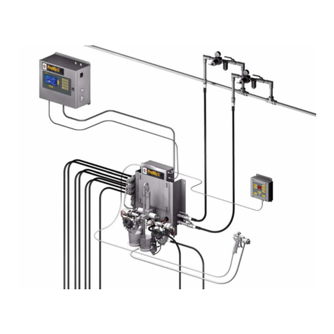
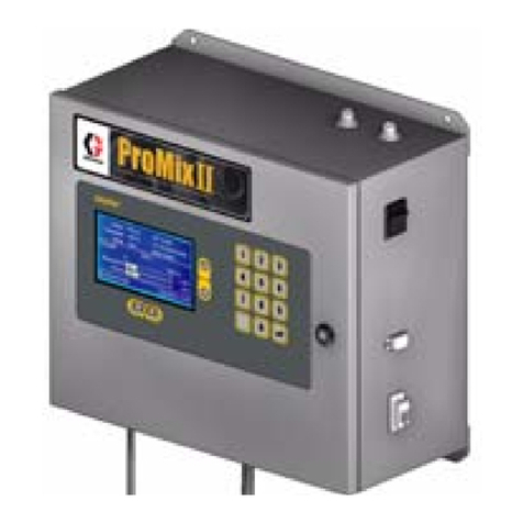
Graco ProMix Easy Series User manual

309908G
ENG
Operation
Self-contained, single color, electronic plural component paint proportioner.
For professional use only.
Important Safety Instructions
Read all warnings and instructions in this manual.
Save these instructions.
See page 3 for model information, including maxi-
mum working pressure and approvals.
TI4909a

Manual Conventions
2309908G
Contents
Manual Conventions . . . . . . . . . . . . . . . . . . . . . . . . 2
ProMix Easy Models . . . . . . . . . . . . . . . . . . . . . . . . 3
Related Manuals . . . . . . . . . . . . . . . . . . . . . . . . . . . 4
Warnings . . . . . . . . . . . . . . . . . . . . . . . . . . . . . . . . . 5
Overview . . . . . . . . . . . . . . . . . . . . . . . . . . . . . . . . . . 7
Usage . . . . . . . . . . . . . . . . . . . . . . . . . . . . . . . . . 7
User Interface . . . . . . . . . . . . . . . . . . . . . . . . . . . 7
Installation . . . . . . . . . . . . . . . . . . . . . . . . . . . . . . . . 8
Mounting . . . . . . . . . . . . . . . . . . . . . . . . . . . . . . . 8
Power Connection (non-IS units only) . . . . . . . . . 8
Air Controls . . . . . . . . . . . . . . . . . . . . . . . . . . . . 10
Solenoid Module . . . . . . . . . . . . . . . . . . . . . . . . 10
Fluid Controls . . . . . . . . . . . . . . . . . . . . . . . . . . 10
Setup . . . . . . . . . . . . . . . . . . . . . . . . . . . . . . . . . . . . 12
Pressure Relief Procedure . . . . . . . . . . . . . . . . . . 14
Fluid Manifold to Gun . . . . . . . . . . . . . . . . . . . . 14
Pump to Fluid Manifold . . . . . . . . . . . . . . . . . . . 15
Flushing . . . . . . . . . . . . . . . . . . . . . . . . . . . . . . . . . 16
Fluid Manifold Flushing . . . . . . . . . . . . . . . . . . . 16
Full System Flushing . . . . . . . . . . . . . . . . . . . . . 18
Priming . . . . . . . . . . . . . . . . . . . . . . . . . . . . . . . . . . 20
Pump Test . . . . . . . . . . . . . . . . . . . . . . . . . . . . . . . 22
Spraying . . . . . . . . . . . . . . . . . . . . . . . . . . . . . . . . . 24
Batch Dispense or Ratio Check . . . . . . . . . . . . . . 25
Pot Life Timer . . . . . . . . . . . . . . . . . . . . . . . . . . . . . 26
Recirculation Setting . . . . . . . . . . . . . . . . . . . . . . . 27
Shutdown . . . . . . . . . . . . . . . . . . . . . . . . . . . . . . . . 28
Recalibrate Pump-based System . . . . . . . . . . . . . 29
Set Pump Calibration Value . . . . . . . . . . . . . . . . 29
Calibrate Pump Sensor . . . . . . . . . . . . . . . . . . . 29
Recalibrate Meter-based System . . . . . . . . . . . . . 30
Calibrate Meter . . . . . . . . . . . . . . . . . . . . . . . . . 30
Set Meter K-factor . . . . . . . . . . . . . . . . . . . . . . . 31
Alarms . . . . . . . . . . . . . . . . . . . . . . . . . . . . . . . . . . . 32
Performance Charts . . . . . . . . . . . . . . . . . . . . . . . . 34
2.5:1 Ratio UltraMix Pump . . . . . . . . . . . . . . . . . 34
24:1 Ratio HydraMix Pump . . . . . . . . . . . . . . . . 34
34:1 Ratio HydraMix Pump . . . . . . . . . . . . . . . . 35
47:1 Ratio HydraMix Pump . . . . . . . . . . . . . . . . 35
Technical Data . . . . . . . . . . . . . . . . . . . . . . . . . . . . 36
Dimensions . . . . . . . . . . . . . . . . . . . . . . . . . . . . . . . 39
Wall Mounting Diagram . . . . . . . . . . . . . . . . . . . . . 39
Graco Standard Warranty . . . . . . . . . . . . . . . . . . . 40
Graco Information . . . . . . . . . . . . . . . . . . . . . . . . . 40
Manual Conventions
Note:
Warnings in the instruction sections (such as “Instal-
lation”) generally include a symbol indicating the hazard.
Follow the instructions and read the hazard section on
the general warning pages 5-6 for additional informa-
tion.
Example:
WARNING
WARNING: a potentially hazardous situation which, if
not avoided, could result in death or serious injury.
CAUTION
CAUTION: a potentially hazardous situation which, if
not avoided, may result in property damage or destruc-
tion of equipment.
Additional helpful information.
WARNING
Your system must be grounded. Read warnings,
page 5 and follow instructions below.
ProMix Easy Models
309908G 3
ProMix Easy Models
* cst=carbon steel. ** sst=stainless steel.
WARNING
Do not install equipment approved only for non-haz-
ardous location in a hazardous area. Substitution of
components may impair intrinsic safety and cause per-
sonal injury. Read page 5.
Approved for Hazardous Location
Class I, Div 1, Group D (North America); Class I, Zones 1 and 2 (Europe)
ProMix
Easy
Part No. Series Description
Maximum Working
Pressure
psi (MPa, bar) Approvals
234596 A Cart mount, UltraMix™cst* Pumps, hose and gun 250 (1.7, 17)
234597 A Wall mount, UltraMix cst* Pump/G3000 Meter 250 (1.7, 17)
234598 A Wall mount, UltraMix sst** Pump/G3000 Meter 250 (1.7, 17)
234599 A Wall mount, UltraMix cst* Pumps 250 (1.7, 17)
234601 A Wall mount, UltraMix sst** Pumps 250 (1.7, 17)
234602 A Wall mount, HydraMix™500 cst* Pump/G3000 Meter 2400 (16, 166)
234603 A Wall mount, HydraMix 500 sst** Pump/G3000 Meter 2400 (16, 166)
234604 A Wall mount, HydraMix 600 cst* Pump/G3000 Meter 3400 (23, 234)
234605 A Wall mount, HydraMix 600 sst** Pump/G3000 Meter 3400 (23, 234)
234606 A Wall mount, HydraMix 500 cst* Pumps 2400 (16, 166)
234608 A Wall mount, HydraMix 500 sst** Pumps 2400 (16, 166)
234609 A Wall mount, HydraMix 600 cst* Pumps 3400 (23, 234)
234611 A Wall mount, HydraMix 600 sst** Pumps 3400 (23, 234)
234612 A Wall mount, HydraMix 700 cst* Pumps 4700 (32, 324)
234613 A Wall mount, HydraMix 700 sst** Pumps 4700 (32, 324)
234618 A Wall mount, G3000 Meter, cst* mix manifold 4000 (28, 280)
234619 A Wall mount, G3000 Meter, sst** mix manifold 4000 (28, 280)
Approved for Non-hazardous Location
234600 A Wall mount, UltraMix cst* Pumps 250 (1.7, 17)
234825 A Wall mount, UltraMix sst** Pumps 250 (1.7, 17)
234607 A Wall mount, HydraMix 500 cst* Pumps 2400 (16, 166)
234826 A Wall mount, HydraMix 500 sst** Pumps 2400 (16, 166)
234610 A Wall mount, HydraMix 600 cst* Pumps 3400 (23, 234)
234827 A Wall mount, HydraMix 600 sst** Pumps 3400 (23, 234)
Conforms to
FM std 3600 & 3610
for use in
Class I Div 1
Group D T3
Hazardous Locations
CAN/CSA
22.2 No. 157-92
& No. 1010.1-92
ISSeP 04 ATEX 020X
EEx ia p IIA T3
0359
9902471
Conforms to
UL61010A-1
Certified to
CAN/CSA
22.2 No. 1010.1-92

Related Manuals
4309908G
Related Manuals
Component Manuals in English This manual available in the following languages:
Manual Description
309908 ProMix Easy Operation
309909 ProMix Easy Repair-Parts
310654 Fluid Mix Manifold
310655 Dispense Valve
310662 UltraMix and HydraMix Displacement
Pumps
310671 UltraMix Pumps
310672 HydraMix Pumps
310673 Circulation Kits
310674 Stand and Caster Kits
310675 AC Power Supply
310676 Remote Manifold Kit
310677 Heater Installation Kit
310678 TSL Pump Kits
310700 Gun Air Regulator Kits
309192 ISO Supply Kit
309623 Data Download Kits
308778 G3000 Flowmeter
308034 Turbine Alternator Repair Kit
Manual Language
309908 English
310679 French
310681 Spanish
310683 German
310685 Italian
310687 Chinese
310689 Japanese
310768 Dutch
310770 Finnish
310772 Swedish

Warnings
309908G 5
Warnings
The following general warnings are related to the safe setup, use grounding, maintenance, and repair of this equip-
ment. Additional more specific warnings may be found throughout the text of this manual where applicable.
Warning
FIRE AND EXPLOSION HAZARD
Flammable fumes, such as solvent and paint fumes, in work area can ignite or explode. To help prevent
fire and explosion:
• Use equipment only in well ventilated area.
• Eliminate all ignition sources; such as pilot lights, cigarettes, portable electric lamps, and plastic
drop cloths (potential static arc).
• Keep work area free of debris, including solvent, rags and gasoline.
• Do not plug or unplug power cords or turn lights on or off when flammable fumes are present.
• Ground equipment and conductive objects in work area. See Setup instructions.
• Use only grounded hoses.
• Hold gun firmly to side of grounded pail when triggering into pail.
• If there is static sparking or you feel a shock, stop operation immediately. Do not use equipment
until you identify and correct the problem.
• Keep a fire extinguisher in the work area.
SKIN INJECTION HAZARD
High-pressure fluid from gun, hose leaks, or ruptured components will pierce skin. This may look like
just a cut, but it is a serious injury that can result in amputation. Get immediate surgical treatment.
• Do not point gun at anyone or at any part of the body.
• Do not put your hand over the spray tip.
• Do not stop or deflect leaks with your hand, body, glove, or rag.
• Do not spray without tip guard and trigger guard installed.
• Engage trigger lock when not spraying.
• Follow Pressure Relief Procedure in this manual, when you stop spraying and before cleaning,
checking, or servicing equipment.
MOVING PARTS HAZARD
Moving parts can pinch or amputate fingers and other body parts.
• Keep clear of moving parts.
• Do not operate equipment with protective guards or covers removed.
• Pressurized equipment can start without warning. Before checking, moving, or servicing equip-
ment, follow the Pressure Relief Procedure in this manual. Disconnect power or air supply.

Warnings
6309908G
EQUIPMENT MISUSE HAZARD
Misuse can cause death or serious injury.
• Do not exceed the maximum working pressure or temperature rating of the lowest rated system
component. See Technical Data in all equipment manuals.
• Use fluids and solvents that are compatible with equipment wetted parts. See Technical Data in all
equipment manuals. Read fluid and solvent manufacturer’s warnings.
• Check equipment daily. Repair or replace worn or damaged parts immediately.
• Do not alter or modify equipment.
• For professional use only.
• Use equipment only for its intended purpose. Call your Graco distributor for information.
• Route hoses and cables away from traffic areas, sharp edges, moving parts, and hot surfaces.
• Do not kink or overbend hoses or use hoses to pull equipment.
• Comply with all applicable safety regulations.
TOXIC FLUID OR FUMES HAZARD
Toxic fluids or fumes can cause serious injury or death if splashed in the eyes or on skin, inhaled, or
swallowed.
• Read MSDS’s to know the specific hazards of the fluids you are using.
• Store hazardous fluid in approved containers, and dispose of it according to applicable guidelines.
PERSONAL PROTECTIVE EQUIPMENT
You must wear appropriate protective equipment when operating, servicing, or when in the operating
area of the equipment to help protect you from serious injury, including eye injury, inhalation of toxic
fumes, burns, and hearing loss. This equipment includes but is not limited to:
• Protective eyewear
• Clothing and respirator as recommended by the fluid and solvent manufacturer
•Gloves
• Hearing protection
Warning

Overview
309908G 7
Overview
Usage
The ProMix Easy can mix most two-component paints. It
is not for use with “quick-setting” paints (those with a pot
life of less than 5 minutes) without modification. Contact
your distributor for information.
The ProMix Easy is operated with the User Interface, Air
Controls and Fluid Controls, described below and on
page 10. Refer to FIG. 1 and FIG. 3.
User Interface
The User Interface has 6 main interfaces.
1. Function Knob to select desired function:
2. Start button to initiate functions.
3. Stop button to terminate functions.
4. Key switch to change ratio, pot life time, pot life vol-
ume, or calibration data.
5. Display (five digits) to view:
• Software revision level at startup
•Ratio
• Pot life time and reset volume
• Alarm codes
• Sensor calibration factor.
6. Data port allows for connection to a PC serial port
to download volume totalizer, operation, ratio set-
ting, and error alarm data.
Icon Function
Spray: proportion and spray material.
Run A: operate A independent of B (prim-
ing, flushing) for 12 cycles (500 cc with
meter).
Run B: operate B independent of A (prim-
ing, flushing) for 12 cycles (500 cc with
meter).
Batch Dispense: dispense proportioned
amounts of A and B (1 pint/500 cc).
Pump Test: dispense predetermined
amount of A and B to verify pump opera-
tion.
Recirculation: circulate fluid A and/or B up
to the mix manifold.
Pot Life Timer: display potlife time left.
Pressure Relief/Park: allows pressure relief
and runs pumps to the bottom of stroke.
See page 14.
• System totalizers count in Spray and Batch
Dispense functions only.
• A and B Indicators (LT) show which dispense
valve(s) is open.
WARNING
To avoid impairing intrinsic safety and reduce the risk
of fire and explosion, the PC must be in a non-hazard-
ous location and a safety barrier must be installed
between the PC and ProMix Easy unit. See ProMix
Easy data download kit manual 309623.
FIG. 1. User Interface
You must recalibrate the circuit board whenever the
main circuit board, software, or sensor is replaced,
or when Alarm 8 occurs. See Recalibrate
Pump-based System, page 29.
3
5
1
2
6
4
LT

Installation
8309908G
Installation
The Typical Installation shown in FIG. 3 is not an actual
system design. Contact your Graco distributor for assis-
tance in designing your system. Be sure all accessories
are adequately sized and pressure-rated to meet sys-
tem requirements.
Reference numbers and letters in the text refer to num-
bers and letters in the figures.
Icons in the text refer to icons on the User Interface.
Mounting
The ProMix Easy may be stand-mounted, cart-mounted,
or wall mounted. Stand and Caster Kits are available to
convert a wall-mount unit. Contact your Graco distribu-
tor.
1. Ensure that the wall and mounting hardware are
strong enough to support the weight of the equip-
ment, fluid, hoses, and stress caused during opera-
tion.
2. Using the equipment as a template, mark the
mounting holes on the wall at a convenient height
for the operator and so equipment is easily accessi-
ble for maintenance. Ensure that the equipment is
level. See Wall Mounting Diagram, page 39.
3. Drill mounting holes in the wall. Install anchors as
needed.
4. Bolt equipment securely to the wall.
Power Connection (non-IS units
only)
ProMix Easy non-IS units operate with 93-250 Vac,
50/60 Hz input power, with a maximum 1.2 amp current
draw. The power supply circuit must be protected with a
15 amp maximum circuit breaker. A switch or circuit
breaker must be must be installed close to the ProMix
Easy, within reach of the operator. The switch or circuit
breaker must be marked as the disconnecting device for
the ProMix Easy.
When the unit is first started up or has been
shutdown for longer than 2 months, you must turn it
on for 8 hours to recharge battery. Reset the date
and time with the Setup program, which is available
with the data download kit.
The unit should be run continuously for 8 hours or
more at least once per month to maintain proper
charge. If the battery is not recharged on a regular
schedule, the date information may be reset. If the
date is reset the date information will be incorrect in
the data log.
Non-intrinsically safe units must be hardwired or
supplied with a power cord (not included). Power
cord must be compatible to your local power con-
figuration. Wire gauge size must be 14 AWG.
Connect the power cord wires (L1, L2, GND) to
the terminal block (Y) in the pneumatic control
box, see FIG. 2.
WARNING
Installing this equipment requires access to parts
which may cause electric shock or other serious injury
if work is not performed properly. Have a qualified
electrician connect power and ground to main power
switch terminals. Read warnings, page 5. Be sure your
installation complies with all National, State, and Local
safety and fire codes.
FIG. 2. Power Cord Connection (Non-IS Units Only)
TI4795a
GND
Y
L2
L1

Installation
309908G 9
Key for FIG. 3
A ProMix Easy Plural Component Proportioner
B User Interface (see page 7)
CMixManifold
D Bleed-Type Main Air Shutoff Valve
E Air Supply Pressure Gauge
F Pump Air Regulator (pump-based units only)
G Pump Air Pressure Gauge (pump-based units only)
H Component A Pump
J Component A Fluid Supply Line
K Component A Fluid Supply (5 gal. pail shown)
L Component B Pump
M Component B Fluid Supply Line
N Component B Fluid Supply (pressure pot shown)
P Gun Air Pressure Regulator (accessory)
R Gun Air Supply Line
S Gun Fluid Supply Line
T Air-Assisted Spray Gun
U Air Line Shutoff Valve
V Proportioner Air Supply LIne
W Ground Wire
FIG. 3. Typical Installation (Wall Mount, Air-Assisted Unit Shown)
TI4791b
N
S
S (Ref)
H
J
K
M
L
R
B
P
C
D
E
WF
VG
A
U
U
T

Installation
10 309908G
Air Controls
See FIG. 3.
•Bleed-type main air shutoff valve (D), to shutoff
all air to ProMix Easy (including controller power).
•Supply air pressure gauge (E), to monitor air pres-
sure to ProMix Easy.
•Pump air pressure regulator (F) with gauge (G),
to adjust and monitor pump air pressure (not pres-
ent on meter-based systems).
•Gun air regulator (P) and gauge, available sepa-
rately to adjust and monitor gun air pressure.
Solenoid Module
There are two solenoids inside the pneumatic control
box, one to actuate dispense valve A, one to actuate
dispense valve B.
Fluid Controls
The ProMix Easy mix manifold includes the following
fluid controls. See manual 310654 for complete informa-
tion about the mix manifold. See FIG. 6.
•Dispense valves (FA, FB)dispense component A
and component B. Solenoids A and B turn the dis-
pense valves ON and OFF.
•Shutoff valves (GA, GB)shutoff fluid A or B from
entering the fluid manifold.
•Sampling valves (HA, HB), to batch dispense or
test pumps/meters.
•Solvent purge valves (JA, JB)allow solvent to
enter the fluid manifold.
A minimum air pressure supply of 70 psi (483 kPa,
4.8 bar) must be maintained for the ProMix Easy
to operate properly.
TI4808a
AB

Installation
309908G 11
Component A Dispense
Solenoid A opens dispense valve A. The correct dose of
component A flows into the integrator (Z). Solenoid A
closes dispense valve A. See FIG. 4.
Component B Dispense
Solenoid B opens dispense valve B. The correct dose of
component B flows into the integrator (Z) and is aligned
proportionately with component A. Solenoid B closes
dispense valve B. The components are pre-mixed in the
integrator, then uniformly blended in the static mixer
tube (ST). See FIG. 5.
FIG. 4. Component A Dispense
Z
FIG. 5. Component B Dispense
ST
FIG. 6. Fluid Mix Manifold
TI4699a
FBOFF FBON
FB
FA
FAON
FAOFF
HA
JAGA
HB
GB
JB
Z
ST

Setup
12 309908G
Setup
3. Tighten all fittings on unit.
WARNING
Do not install equipment approved only for non-haz-
ardous location in a hazardous area. Substitution of
components may impair intrinsic safety and cause per-
sonal injury. Read warnings, page 5. Ground equip-
ment as instructed below.
1. Connect ProMix Easy ground wire (W) to a true
earth ground.
Non-intrinsically safe units must be hardwired or
supplied with a power cord (not included). See
page 8.
2. Connect the fluid hose (S) to the fluid manifold out-
let. Do not install gun spray tip yet.
W
TI4792a
TI4793a
S
4. Pump-based models only: Fill pumps A and B pack-
ing nuts with throat seal liquid (TSL).
5. Connect air supply line (V) to air inlet.
Air supply requirement: 110 psi (0.8 MPa, 8 bar)
maximum, 70 psi (483 kPa, 4.8 bar) minimum.
Flow volume required: 20 scfm minimum; 125
scfm maximum.
V

Setup
309908G 13
8. Setup ratio.
a. Turn function knob to .
b. Current ratio displays.
9. Flush and prime system. See pages 16 and 20. Run
Pump Test, page 22 to check ratio accuracy.
6. Pump-based models only: Set air regulator to 0.
7. Open main air shutoff valve. When starting up, dis-
play will show “88888”, then software revision, then
current ratio (if set to or ).
c. To change ratio, turn key to + or – until desired
ratio is displayed, then turn key back to neutral.

Pressure Relief Procedure
14 309908G
Pressure Relief Procedure
Fluid Manifold to Gun
WARNING
Relieve pressure from fluid manifold to gun whenever
you stop spraying and before servicing gun or remov-
ing spray tip.
In addition, relieve pressure from pump to fluid mani-
fold at end of day and before cleaning, checking, or
servicing pump, manifold, or fluid line accessories or
transporting equipment.
Read warnings, page 5.
1. Engage trigger lock.
2. Press .
3. Disengage trigger lock.
4. Hold a metal part of the gun firmly to a grounded
metal pail. Trigger gun to relieve pressure.
5. Engage trigger lock.

Pressure Relief Procedure
309908G 15
Pump to Fluid Manifold
1. Close shutoff valves GAand GB.
2. Place waste container under sampling valves HA
and HB.
3. Turn function knob to pressure relief/park .
4. Press . Indicator A comes on, and Pump A pres-
surizes.
TI4699a
HB
GB
HA
GA
5. Open sampling valve A slowly to bleed off pressure.
Indicator A will stay on for 5 sec after Pump A
reaches Park position, then go off.
6. Indicator B comes on and Pump B pressurizes.
7. Open sampling valve B slowly to bleed off pressure.
Indicator B will stay on for 5 sec after Pump B
reaches Park position, then go off.
If both pumps are not parked after 1 min, Alarm
26 will sound.
8. Close sampling valves A and B before restarting
system.
Pump air supply pressure must be sufficient to
cause pumps to stroke to bottom-most position
when function knob to is set to pressure relief/park
.

Flushing
16 309908G
Flushing
There are times when you only want to flush the fluid
manifold, such as:
• breaks in spraying
• overnight shutdown
• end of potlife
In this manual, that procedure is referred to as Fluid
Manifold Flushing. You can flush the fluid manifold by
connecting a solvent pump to the fluid manifold.
Other times, you need to flush the entire system:
• first time material is loaded into equipment*
• color change
•servicing
• shutting down equipment for more than 3-1/2 hours
(depends on material)
• putting equipment into storage
*Some Full System Flushing steps are not necessary for
initial flushing, as no material has been loaded into the sys-
tem yet.
To flush the entire system, you first follow the Fluid
Manifold Flushing procedure, at right, then the Full
System Flushing procedure, page 18.
Fluid Manifold Flushing
Using Solvent Pump
WARNING
Read warnings, page 5.
• Use the lowest possible pressure when flush-
ing to avoid splashing.
• Before color change or shutdown for storage,
flush at a higher flow rate and for a longer
time.
• A circulation setting is available. Consult your
distributor. Refer to page 27.
1. Follow Pressure Relief Procedure, page 14.
Engage trigger lock. Remove spray tip.
2. Ensure that shutoff valves GAand GBare open.
Connect solvent pump line to solvent purge valve JA
and JB. Turn on solvent pump and open solvent
purge valve JA.
3. Adjust solvent pump regulator to desired pressure;
use lowest pressure possible.
TI1948A
TI1948A
TI4699a
JB
JAGA
GB

Flushing
309908G 17
4. Disengage trigger lock and trigger gun into a
grounded pail. Flush out about 1 pint (500 cc) of
mixed material. Engage trigger lock.
5. Close solvent purge valve JA.
6. Open solvent purge valve JB. Flush out about 1 pint
(500 cc) of mixed material. Engage trigger lock.
7. Re-open solvent purge valve JA.
AB
JB
JA
AB
JB
JA
8. Disengage trigger lock, and flush through gun until
clean solvent flows. Engage trigger lock.
9. Close solvent purge valves JAand JB.
10.Trigger gun to relieve solvent pressure. Engage trig-
ger lock.

Flushing
18 309908G
Full System Flushing
2. Replace component A and B supply with solvent.
3. Set air regulator to 50 psi (345 kPa, 3.4 bar).
5. Ensure shutoff valve GAis open. Open sampling
valve HAslowly. Pump A will run for 12 cycles, then
stop. Restart as needed. When clean solvent flows
from sampling valve HA, close valve.
6. Trigger gun into grounded pail. Dispense about 1
pint (500 cc) of material, then press .
7. Open solvent purge valve JA. Turn on solvent pump.
8. Trigger gun into a grounded pail. Dispense about 1
quart (1000 cc) of material.
9. Close solvent purge valve JA.
1. Follow Pressure Relief Procedure, page 14.
Engage trigger lock. Set air regulator to 0, and close
main air shutoff valve. Remove spray tip and soak in
solvent.
4. Turn function knob to A . Press .
TI1948A
TI1948A
TI4699a
JB
JAGA
GB
HA
HB
HA
If the pump does not start when you trigger the
gun, increase the air pressure by 10 psi (69 kPa,
0.7 bar) increments; to avoid splashing, do not
exceed 70 psi (483 kPa, 4.8 bar). If the pump still
does not start, the solvent may have caused your
packings to swell and it is recommended you use
Tuff Stack™Packing Kit.
AB
JA
AB
JA

Flushing
309908G 19
11.Ensure shutoff valve GBis open. Open sampling
valve HBslowly. Pump B will run for 12 cycles, then
stop. Restart as needed. When clean solvent flows
from sampling valve HB, close valve.
12.Trigger gun into grounded pail. Dispense about 1
pint (500 cc) of material, then press .
13.Open solvent purge valve JB. Turn on solvent pump.
14.Trigger gun into a grounded pail. Dispense about 1
quart (1000 cc) of material.
15.Open solvent purge valve JA. Trigger gun into
grounded pail and flush until clean solvent flows
from gun.
16.Close solvent purge valves JAand JB.
17.Follow Pressure Relief Procedure, page 14, and
remove gun from hose. See gun manual to further
clean gun.
10.Turn function knob to B . Press .
If the pump does not start when you trigger the
gun, increase the air pressure by 10 psi (69 kPa,
0.7 bar) increments; to avoid splashing, do not
exceed 70 psi (483 kPa, 4.8 bar). If the pump still
does not start, the solvent may have caused your
packings to swell and it is recommended you use
Tuff Stack™Packing Kit.
HB
AB
JB
Some materials require additional cleaning. You
may need to circulate solvent through the system.
AB
JB
JA
AB
JB
JA

Priming
20 309908G
Priming
Do not install the gun spray tip yet. Use the lowest
possible pressure while priming, to avoid splash-
ing.
1. Connect A and B fluid supply hoses to A and B
pumps/meters.
2. Pump-based models only: Set air regulator to 0.
3. Close fluid shutoff valves GAand GB.
GA
GB
4. Place a container under each sampling valve. Open
sampling valve HAslowly.
5. Turn function knob to A . Press . On
pump-based models only, turn up air regulator
slowly until pump A starts.
HA
When run independently (set to A or B), the pump
runs for 12 cycles, then stops. Press and
as needed to prime. Monitor containers to avoid
overflowing.
Table of contents
Other Graco Mixer manuals

Graco
Graco 25C483 Parts list manual

Graco
Graco ToughTek CM20 Instruction Manual

Graco
Graco 26C150 User manual

Graco
Graco Hydra-Cat 207-388 F Datasheet

Graco
Graco ProMix II Series Guide

Graco
Graco 236661 User manual

Graco
Graco ToughTek CM20 User manual

Graco
Graco 25C539 Parts list manual

Graco
Graco Twistork A Series Operation manual

Graco
Graco ProMix 3KS User manual

Graco
Graco 24C728 Parts list manual

Graco
Graco PrecisionMix ii Datasheet

Graco
Graco ProMix II User manual

Graco
Graco ProMix 2KS User manual

Graco
Graco DataTrak kit User manual

Graco
Graco XTREME MIX 309521J User manual

Graco
Graco 222695 User manual

Graco
Graco Xtreme Mix OEM User manual

Graco
Graco 226086 User manual