IMET KS 450 FT User manual

TRADUCTION OF THE ORIGINAL USER’S INSTRUCTIONS
KS450FTeng ED.2011 rev.34 1
IMET Spa
Loc. Tre Fontane - Cisano Bergamasco
Tel. 035/4387911 - Fax. 035/787066
eb site: www.imetsaws.com
E-mail: imet@imetsaws.com
Semiautomatic hydraulic bandsaw KS 450 FT
USER’S INSTRUCTIONS

TRADUCTION OF THE ORIGINAL USER’S INSTRUCTIONS
KS450FTeng ED.2011 rev.34 2
1-
1- INTRODUCTION
We recommend to read carefully the information here included in order to install, use and maintain correctly and
safely this machine.
Please refer always to this instruction manual in case of assistance service need and keep it carefully for all the
machine life. The reference number is shown on the cover.
A consequence of the continuous improvement of the product is that some images/descriptions here included could
not correspond to the improved features of the machines.
Your kind collaboration would help us to provide a faster service.
1.1 - ATTACHED DOCUMENT FOR E.M.C. ( INDUSTRIAL ENVIRONMENT)
The user is responsible for the installation and use of this machine in compliance with the
manufacturer's instructions shown in this manual. This equipment meets the protection
requirements in accordance with the Directives 2006/42/EEC, 2004/108/CE for Electromagnetic
Compatibility (EMC). In particular, it follows the technical guidelines of the Directives EN55011,
EN50082-2 and it has been made for industrial and not for household use.
In the event of electromagnetic interferences the user is responsible for solving the problem with
the help of the technical assistance by the manufacturer. Before installing the machine the user
must take into account possible electromagnetic problems of the working area. In particular, we
suggest to install the machine away from:
-signalling, control and telephone cables;
-radio-television transmitters and receivers;
-computers or controlling and measuring instrument;
-safety and protection devices.
The electric supply cable must be kept as short as possible, without any twists.
Covers, doors and the frame must be suitably closed when the saw is operating.
Under no circumstances the machine must be modified except for adjustments and changes
specifically approved by the manufacturer. Follow the maintenance schedule.
In the enclosed Conformity Declaration
you will find the Safety and Reference
Norms applied during the planning and
construction of this machine; please
keep this document as long as you use
this saw. In the following page you can
see a copy of such Declaration.
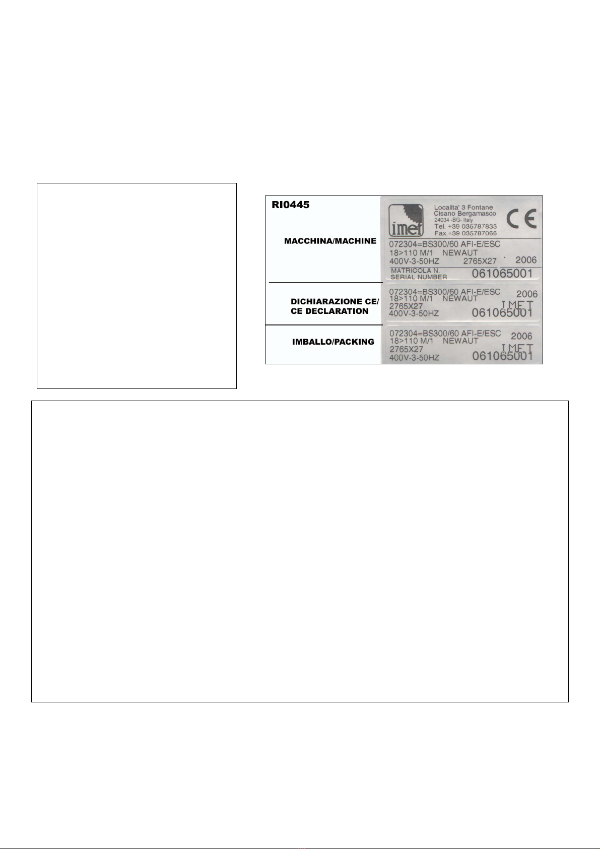
The identification plate - shown below -
with the serial number is applied on the
lower side of the saw or on the control
panel if present, on the Conformity
Declaration and on the packing.

TRADUCTION OF THE ORIGINAL USER’S INSTRUCTIONS
KS450FTeng ED.2011 rev.34 3
2
===========================================================================
CE DECLARATION OF CONFORMITY (encl. II A DIR 2006/42/CE) / 01
===========================================================================
THE MANUFACTURER : IMET S.p.A
Località Tre Fontane
24034 - CISANO BERGAMASCO –BG- ITALIA
HEREBY DECLARES THAT
in designing and manufacturing the machine described here below , we have considered the most important
requirements of safety and health dictated by the European Directives of the Machine Security. Remember that this
declaration loses its validity if machine is modified without our agreement.
Trade name BAND SAWING MACHINE FOR METALS
Code / Model / Type
Manufacturing year
Serial number
IT IS IN COMPLIANCE WITH THE DIRECTIVES
DIRECTIVE 2006/42/CE OF THE EUROPEAN PARLIAMENT AND OF THE COUNCIL OF THE
17TH/05/2006 REGARDING THE MACHINES AND THAT MODIFIES THE DIRECTIVE 95/16/CE;
DIRECTIVE 2004/108/CE OF THE EUROPEAN PARLIAMENT AND OF THE COUNCIL OF THE
15/12/04 REGARDING THE ELECTROMAGNETIC COMPATIBILITY -EMC-
DIRECTIVE 2006/95/CE OF THE EUROPEAN PARLIAMENT AND OF THE COUNCIL OF THE
12/12/06 REGARDING ELECTRICAL EQUIPMENT FOR USE OF LOW VOLTAGE -LVD-
HARMONIZED STANDARDS REFERENCE EN12100-1, EN12100-2; EN 55011, EN50082-2, EN 13898, EN 60204
LEGISLATIVE DECREE N.17 OF THE 27TH OF JANUARY 2010.
AND AUTHORIZING THE PERSON LISTED BELOW TO ISSUE TH
AND AUTHORIZING THE PERSON LISTED BELOW TO ISSUE THE TECHNICAL FILE.
E TECHNICAL FILE.
E TECHNICAL FILE.
E TECHNICAL FILE.
Date : 01.01.2010
The signatory identification The manager
Angelo Meroni
--------------------------------------------------------------------------------------------------------------------------
File : Machine no. Delivery note no Dated
--------------------------------------------------------------------------------------------------------------------------
…………………….
ORIGINAL WITHIN THE MACHINE..
………………..

TRADUCTION OF THE ORIGINAL USER’S INSTRUCTIONS
KS450FTeng ED.2011 rev.34 4
3 - MACHINE NOISE
The noise level of the working area - given the conditions described below - is determined by the
simultaneous working of several parts of the machine in motion (according to the working cycle),
in addition to the tool when cutting the material.
The noise level is detected in different moments, corresponding to different working phases. The
proper device is placed about 1 meter near the machine and about 1,60 m above the floor.
The results of each test is in dBA and they are the average of 3 tests made from the left
side, opposite side and right side.
For any machines the working conditions are the following:
When idle, at the maximum blade speed: dBA 63
During the cut, at a suited blade speed, cutting solid steel (St12=≈C20, 200 mm diameter):
dBA 75
(tolerance ± 2dB).
In the standard production the test is made on a machine like this, in compliance with E.C. safety
norms 2006/42/CE and EN13898. Using the saw in bad conditions or using wrong tools causes
significant alterations of these tests and it jeopardizes the health of the staff and the good results
of the work. Useful is the European Guideline 2003/10/CE.
The noise depends mostly on the cutting material, on its size and on the clamping. Considering
that the above mentioned decibels could be exceeded, we recommend the operator to use
personal protections (headsets, plugs, and so on) when working for a long time with high noise
levels.
3.1 - ADDITIONAL HEALTH AND SAFETY REQUIREMENTS
The machines manually controlled by an operator during all work phases must comply to further
health and safety requirements as specified by article 2.2 of the Annexed I of the European
Directive 2006/42/CE and following integrations. In particular, the level of the machine vibrations
when working must be clearly specified in the instructions.
This machine does not produce vibrations higher than 2.5 m/s2
The measurement procedure is in compliance with the general norms applied to this type of
machinery.
As in the previous paragraph, using the machine in unsuitable conditions or using the
wrong tools can cause changes affecting this value, causing a risk to the health of the
working staff as well as the quality of the production. Useful is the European Guideline
2002/44/CE.
Vibrations produced during the cut may be amplified by the material, by its dimensions and
its positioning/clamping in the vice.

TRADUCTION OF THE ORIGINAL USER’S INSTRUCTIONS
KS450FTeng ED.2011 rev.34 5
4 - GUARANTEE NORMS
IMET offers a wide range of sawing machines and accessories, destined to those who buy/use them as part of a
commercial or professional activity.
The manufacturer grants that this product has been carefully checked and that there are no defects in the
components as well as in the working materials employed, for a period of 12 months after the date of the delivery
note.
The Italian D.L. n° 24 issued on 02/02/2002 and valid since 23/03/2002 (which carries out the European Directive
1999/44/CE) indicates different terms only for convenience products for private use.
If the user points out some defects to the manufacturer during the warranty time, the manufacturer will replace the
components that are considered faulty.
In case of reparation of the machine during the warranty time the shipment to Imet will be accepted only if the delivery
is Free Destiny (that is, the freight costs are charged to the owner of the machine), while the shipment back to the
customer is EX WORKS.
If the manufacturer is not able to replace a component within an acceptable time, both companies (manufacturer and
user) will reach an agreement for satisfying completely the needs of the user.
The a.m. warranty is not valid in case of accidental damages, defects caused by a wrong use of the saw or wrong
maintenance, by variations made on the machine, or by the use of it in a place not corresponding to the required
environmental specifications.
4.1 - The manufacturer does not offer further warranties, written or verbal, explicit or implicit for its products and does
not offer implicit warranties on sale potential or compliance with particular uses not foreseen by the original
agreement.
The a.m. limitations and exclusions can also be not applicable in Countries, where there are no implicit limits of
warranty time on the products. Anyway each implicit warranty is limited to a time of 12 months after the date of the
delivery note.
4.2 - The date of manufacture, which can be inferred from the serial number placed on the machine, is a necessary
reference for the warranty, for the after-sale assistance and the identification of the product.
Each modification of the products, especially the installation of safety devices, will relieve the manufacturer of any
kind of responsibility.
The parts which are most subject to rapid and continuous wear are not included in the warranty (for example:
transmission belts, gaskets, oils, blades, and so on).
For electrical, electronic and hydraulic equipments and for other equipments whose manufacturer can be identified,
the manufacturer gives to the user the same warranty received by the primary producer of these parts.
4.3 - The components replaced during the assistance supplied by the manufacturer have a warranty of 6 months
after the installation date indicated on the Technical Service report, one copy of which is given to the owner of the
Date of purchase…………………….. ………………….
Date of installation………………… ………………….
Reseller………………………….. ………………….

TRADUCTION OF THE ORIGINAL USER’S INSTRUCTIONS
KS450FTeng ED.2011 rev.34 6
5 - SUMMARY Page
1- INTRODUCTION 2
2 – CONFORMITY DECLARATION 3
3 – AIR NOISE 4
4 – GUARANTEE NORMS 5
5 – Index 6
6 – Technical characteristics 7
7 – Installation – minimum requirements 9
8 – Moving and transit 9
9 – Fittings/optionals 10
10 – Blade choice 11
11 – Correct use and contraindications 12
12 – Machine description 15
13 – Work preparation 16
14 – Band tensioning 17
15 – Functioning 19
16 – Regulations 23
17 – Maintenance – for the user 24
18 – Band running-in 25
19 – Machine running-in 26
20 – Draining of used/produced substances 26
21 – Trouble-shooting 27
22 – Machine demolition 29
23 – Spare parts 29
24 – Maintenance – for qualified technicians 31
Electrical drawings
Spare Parts drawings

TRADUCTION OF THE ORIGINAL USER’S INSTRUCTIONS
KS450FTeng ED.2011 rev.34 7
6 - TECHNICAL CHARACTERISTICS
Hydraulically driven semiautomatic bandsaw. Sui
ted for cutting metal profiles and solids from 60° left to 60° right. In
compliance with CEE Safety Standards and Electromagnetic Compatibility Norms (EMC). Steel sawframe with tubular
section; worktable supported by preloaded central bearing. Automatic st
ops at the positions 45° left, 45° right and 0°.
Adjustable taper rollers located on the rocking pin. 360mm pulleys, Long Life reducer. Blade-
driving guides with hard
metal pads and driving bearings. Equipped with a new compact base and a worktable with presetted passages for
the blade line on most used angles. Easy positioning of the vice, with fully hydraulic stroke on 450 mm, along the
woktable width, with manual clamping.
STANDARD VERSION COMPLETE WITH:
-electric equipment complying with E.C. Norms EN60204-1, EN-55011, EN-50082-2, 2 speed three-phase motor ;
-general switch which can be locked, minimum tension coil, thermo-
magnetic overloads motor protection, emergency
button, warning light for low tension 24V, for blade tensioning, for blade cover and motor overload.
-cutting cycle: AUTOMATIC fast approach of the sawframe to the cut-
start point, then the machine adopts the cutting
speed until reaching the cut-end point, which is checked by a microswitch; as a final step, the sawframe goes back to
the cut-start position and the blade stops.
-hydraulic regulators for feed speed and feed force, located on control consol
-mechanical blade tensioning up to 1700 kg/cm
2
, microswitch for checking the tension, instant stop in case the blade
breaks or is not tensioned -
hydraulic front vice free to move transversally on the worktable, ; hydraulic vice opening
460 mm, jaws height 180 mm
-blade-cleaning device by means of a motorized brush
-floor stand equipped with removable chips collector and apt to be moved with forklift; hydraulic unit with oil; tank and
electric pump for coolant; bi-metal band.
-wrenches and manual of instructions, maintenance and spare parts.
VARIATIONS BE MENTIONED WHEN ORDERING THE MACHINE
Blade size 34 x 1,1x 4250 mm by a longer saw frame structure.
Electronic Speed Control –ESC- which grants a continuous blade speed variation by an inverter on the motor.
If not differently indicated, all data reported in this manual refer to the standard version, suitable for working at
400 V / 50 Hz THREEPHASE.
= cutting capacity ( max. dimensions on PROFILES & TUBES)
= BLADE DIMENSIONS = WEIGHT =VICE OPENING
= motor choice and blade speeds (at 50 Hz);
Dimensions
( cm ) B L
H
mm Kw Mt/min mm Kg
In use 140 225 218
ON REQUEST
4250X27X0,9
1,7 - 2,2
3~ 35 and
70 460 830 net
825 gross packed 140 245 180
ON REQUEST
4250x27x0,9 ESC - 2,2
3~ from 15
to 100 460 835 net
830 gross
4250X34X1,1
1,7 - 2,2
3~ 35 and
70 460 860 net
855 gross
4250x34x1,1 ESC - 2,2
3~ from 15
to 100 460 865 net
860 gross
WORKTABLE MIN. HEIGHT = 850 mm

TRADUCTION OF THE ORIGINAL USER’S INSTRUCTIONS
KS450FTeng ED.2011 rev.34 8
Into brackets ( ) the cutting capacity without fast approaching plate
SECTIONS
ANGLE
ROUND SQUARE RECTANGULAR
RECTANGULAR.
PROFILE
0°
310
(350) 280
(330) 450X270
(450X320) IPE 450X190
(HEB 450X300)
45°
300
(330) 270
(320) 320X270
(320X300) IPE 300X150
(HEB 320X300)
60°SINISTRA
210 200 180X270 HEB 200X200
60° DESTRA
160 150 150X270 HEB140X140
7 – INSTALLATION
This machine works according to the parameters provided by the manufacturer if it is correctly installed and the
minimum requirements are observed, as follows :
- It must be used indoor and with temperatures ranging from +5 to + 40 ° C.
- The relative humidity of the environment must not be above 95%.

TRADUCTION OF THE ORIGINAL USER’S INSTRUCTIONS
KS450FTeng ED.2011 rev.34 9
- The nominal value of the voltage of electric energy must be between ± 10% and the frequency of the nominal value
must be between ± 2%.
The floor must have good characteristics of capacity and level.
Floor space, operator position and working area are indicated in the included drawing that concerns the machine only
without fittings as optional.
The Worktable must be leveled: by using the screws and nuts located in the little feet holes, it has to be fixed to the
floor (it is especially necessary with connected accessories).
The included electrical schemes give the necessary information to arrange the connections, to be fit for 4 KW
power request.
Earthing of all the electric parts with a dedicated GREEN/YELLOW wire, connected with a TN system to the
supply cable. A supplementary earthing point – indicated with PE – can be located on the metallic structure
of the machine.
At the origin of the power supply cables a device (such as fuses) to protect against overloading has to be
installed. On the models equipped with electronic variable-speed drive unit (ESC), in order to connect the
differential protection on the power supply line, switches with a threshold of interference on the power
dissipation of not less than 300 mA (size 0.3 A or higher is recommended) have to be employed, having
possibly time adjustment availability (0>1.5 sec).
E.M.C. - Electromagnetic noise
The user is responsible for installing and using this saw according to the manufacturer’s guidelines outlined in this
manual. This equipment complies with the protection requirements established by the Directives 2006/42/CE,
2004/108/CE, concerning Electromagnetic Compatibility (EMC). It is in compliance also with the technical guidelines
of the Norms EN 55011, EN 50082-2 and it is intended for industrial and not for household use.
Before installing the machine the user must take into account possible electromagnetic problems of the working area.
In particular we suggest to install the equipment away from:
- signalling, control and telephone cables;
- radio-television transmitters and receivers;
The supply cable has to be as short as possible, with no twists. All doors, coverings and frame have to be closed
when the saw is running. Do not make any modifications to the machine except for adjustments and replacements
allowed/recommended by the manufacturer. Follow the maintenance schedule.
8 – TRANSPORT & LIFTING
The machine has to be transported following the recommendations given below. However, be sure that the means of
transport and lifting are able to stand the machine's weight and its packing (about 900 Kg).
WARNING
The personnel in charge of loading, unloading and moving the machines should use protective gloves.
WARNING
When lifting or moving the machine, or a part of it, take care of clearing the operations area of people, consider also
an appropriate safety area around it, so as to avoid any risks of injuring people or damaging things located nearby.
Special packing – wooden crate , wooden case – may be arranged on request, and the related expenses will be
charged to the customer.
ALL THE OPERATIONS THAT INVOLVE MOVING THE MACHINE MUST BE PERFORMED WHILE RESPECTING
THE FOLLOWING BASIC RULES:
+ When moving the machine, an appropriate means has to be used, with a loading capacity higher than the weight
to lift, which is indicated on the machine.
+ When choosing and then using equipment such as ropes, chains or lifting belts, be careful about their positioning
during the lifting and about the consequent actual loading capacity.
+ The machine is structured so as to offer lifting points, which are appropriately indicated and will have to be used
for lifting it.
+ In case the lifting belts touch parts of the machine, nylon belts are required; ropes or chains wrapped with jute or
clean covering can also be used. A great care is necessary while slinging and moving the saw in order to hinder
damages.
+ All operations have to be conducted gradually, so as to avoid jolts and dangerous situations.

TRADUCTION OF THE ORIGINAL USER’S INSTRUCTIONS
KS450FTeng ED.2011 rev.34 10
+ The person in charge of the operations has to make sure that all the national, local and company norms in
reference to injury prevention and work safety are observed.
+ One or more areas for material storage have to be identified.
Transport with machine at sight
This type of transport is usually chosen for deliveries by closed truck, in case of short trips. The machine is wrapped
with thermoplastic material in order to assure a suited protection of all its parts; it is then loaded on a truck and should
be wrapped with ropes that tie it up. To lift it, use a forklift from the front side of the saw, with forks 1.5 m long or more.
Warning: if machine is delivered by open trucks, please cover it !
Shipment with wooden crate or wooden case. ( ON REQUEST, COST CHARGED TO THE CUSTOMER)
The machine is wrapped with thermoplastic material in order to assure a suited protection of all its parts; then it is
packed into a wooden crate or cage to protect it from hits, inclement weather and so on.
To lift it, use a forklift from the front side of machine, with forks 1.5m long or more (see picture ).
You need to follow the indications you find on the packing before proceeding to moving or opening it.
WARNING
The size of the packing varies according to the machine and its configuration.
WARNING
The saw is fixed to the packing by means of screws, so as to hinder it from moving during the shipment (see drawing
in the following page)
9 - ACCESSORIES ASSEMBLING
The necessary information for the installation are given along with the accessories. Anyway you can find here a short
description of how they work:
Connection element RAKS450 - OPTIONAL - Required to connect in solidarity any material support roller to the
loading or unloading.machine side. Fix and regulate it by the 4 screws just supplied, on each ; also place in order the
metal sheet to avoid coolant splash at the beginning of the roller line.
Loading/Unloading Roller Tables RTS Optional : it is comprised of modular steel units, each 1.5 meter long and
equipped with 5 rollers. The loading capacity is 1500 kg. It must be fixed to the side - left and right - of the saw, to
guarantee the stability of the material that is going to be cut. To level
the height of the rollers, place a bar on the worktable and clamp it,
then adjust all the screws until the table is perfectly in line with the
saw.
To rightly install the loading roller table,
first of all it is necessary to level and to
adhere the machine.
Therefore level the loading roller table to
the same level of the work table and the
back supporting jaws by beginning to
that nearest the machine.
The alignment of the loading/unloading
tables must begin with the one closer to
the machine, taking as reference point
the worktable and the back jaw. When
cutting long bars, fix the table to the floor
and make sure the coolant, which is
carried by the bars, doesn’t drop on the
floor.

TRADUCTION OF THE ORIGINAL USER’S INSTRUCTIONS
KS450FTeng ED.2011 rev.34 11
If your working process require it, on the unloading side you can choose to use the roller table with manual
measuring system with digital readout (RTL) or the one with digital measuring system and automatic positioning of
the stop (RTP) also.
This last device must be connected to the machine by a special device – ITEM 000910-01 –to sinchronize the
movement of the saw frame within the automatic backwarding of the lenght stop.
Inverter for variable blade speed - ESC - is an accessory which can be installed when manufacturing the saw and
allows the blade to have a variable speed. It can be adjusted by means of a selector located on the control panel.
In case the maximum power supply threshold is exceeded - for example, because of an excessive cutting pressure or
because the blade remains stuck into the material - the Inverter stops the motor. To restore it, the main switch has to
be turned to 0 (OFF), wait for about one minute and then turn it on I (ON).
In the meantime, try to find out the reason that caused the interruption and eliminate it.
Voltage transformer - place it between the electric equipment of the building and the electric supply of the machine. It
allows to work with a different voltage than the standard one (that is 400V / 50 Hz).
Available voltages: 230V, 460V, 500V, 575V.
Minimal lubrication – THE MINIMAL LUBRICATION SYSTEM APPLIED TO THE BANDSAW ALLOW TO ELIMINATE
ALMOST COMPLETELY THE TRADITIONAL COOLANT SYSTEM. THE MATERIAL IS MUCH CLEANER AND
THERE IS NO WASTE/SPILLING OF COOLANT AND WATER, CONTRIBUTING THUS TO PRESERVING NON-
RENEWABLE ENERGY SOURCES AS WELL. IT IS ACTIVE ONLY DURING THE CUT.
IT IS COMPRISED OF A NOZZLE – F00f197m – WITH 3 MICRO-HOLES TO SPREAD THE OIL ON THE BLADE, A
TANK WITH DEVICE TO ADJUST THE OIL FLOW AND ANOTHER TO REGULATE THE AIR PRESSURE. THE
24V LOW TENSION SWITCH ALLOWS TO STOP IT AT ANY TIME AND USE THE NORMAL STANDARD
COOLANT SYSTEM.
Unloading Roller Table RTL with
digital readout (Optional): it is
comprised of an RTS with the addition of
a measuring device equipped with digital
readout, powered by one size A battery.
It is available in 3- and 6-meter units. To
connect to the right side of the saw.
.
Unloading Roller Table with
motorized positioning RTP (Optional):
it is comprised of the RTS roller table
and a motorized bar-stop. The blade
movement can be synchronized with the
ongoing control of the cutting lengths.
Available in 3- and 6-meter units to be
connected to the right side of the
machine.

TRADUCTION OF THE ORIGINAL USER’S INSTRUCTIONS
KS450FTeng ED.2011 rev.34 12
10 - BLADE CHOICE for KS 450
In this paragraph we recommend the type of blade to use according to the material that must be cut. To get the best
performance it is essential to understand the correct applications and limitation of the tools.
These machines have the possibility to be ordered and built in two different saw blade size, which uses
different saw blade dimensions, as follow indicated -measures in mm-:
Standard feature 4250 x34x1,1
maximum length = 4260 minimum length = 4240 height = 34 thickness = 1,10
By request 4250 x27x0,9
maximum length = 4260 minimum length = 4240 height = 27 thickness = 0,90
In the past the measure wa 3930x27x0,9
maximum length = 3940 minimum length = 3920 height = 27 thickness = 0.90
Because is not possible to interchange the different sizes on the machine, verify the right dimension looking
on the identification plate and/or ask to the manifacturer by using the serial number.
Blades with a different thickness can be utilized by changing appropriately the width of the blade guides (see the
paragraph ADJUSTMENTS ) and the band tension.
The blade material is also important; generally the bi-metal blade is used, with different levels of HARDNESS, named
M42 or SVGLB (for general purpose: tube, solids and profiles, available in all pitches), M51 or SHL (preferred
for big solids of hardened steel, INOX material too, available in 3/4 and 2/3 pitch).
The teeth hardness increases - and the fragility too - by going from the material M2 to the M51.
To make a good cut it’s crucial to choose the right pitch (t) or NUMBER OF TEETH PER INCH (z). The blade
must generally have the toothing as follows:
- small teeth when cutting thin materials, tubular and profiles.
- big teeth when cutting solids or pieces with a long cutting section (for example the central part of a U profile), or in
case of softer materials such as aluminium, copper, soft bronze.
By choosing the suited pitch you can avoid a lot of mistakes and you can get a good blade penetration and the
necessary room for the chips. If you cut more pieces at the same time, you must consider them as a single
piece (that is, you have to consider the total size). The enclosed chart gives the necessary information for a
correct choice. It can however be updated or modified by the user according to his personal experiences.
Even if there are blades with constant pitch, most bandsaws allow the use of blades with variable pitch, that is, groups
of teeth having different pitch one from each other, which reduce vibrations and noise and improve the quality of the
cut and the cutting performance.
SUGGESTED PITCH SOLIDS
Outer
Diameter
(mm)
BIG
PROFILE
S
Wall
Thickness
(mm)
PROFILES
Wall
Thickness
(mm)
BUNDLE
Lenght
to Cut
(mm)
REF.

TRADUCTION OF THE ORIGINAL USER’S INSTRUCTIONS
KS450FTeng ED.2011 rev.34 13
VARIABLE CONSTANT
14 M42 - - 1,5 max -
10/14 M42 10 M42 - - 1 to 2 -
8/12 M42 8 M42
20 max - 2 to 4 -
6/10 M42 6 M42 40 max - 4 to 8 -
5/8 or 5/7 M42 5 M42
30 to 80 6 to 12 - 50 to 100
4/6 M42 4 M42 40 to 100 10 to 16 - 70 to 150
3 / 4 M42 or M51 3 M42 or M51 70 to 150 15 to 30 - 120 to
250
2/3 M42 or M51 2 M42 or M51 120 to
280
over 30 - 200 to
400
These cutting recommendations refer to 100 mm. diameter solid bars and a standard saw of our product
range. For 2-speed machines we suggest the motor speed to use; when it’s into a bracket ( ) it is recommended to
use a machine with ESC, which grants a continuous blade speed variation.
If the size of the material decreases, the indicated figures can be increased, considering also the machine model
and its performance and/or some accessories, for example the ESC (Electronic Speed Control):
If the material size increases, it is necessary to decrease the indicated values, considering also the machine
model and its performance and/or some accessories, such as the ESC (Electronic Speed Control):
MATERIAL
GROUP i.e. DIN
denomination DIN N° Maximum
BLADE
SPEED
m/min
Minimum
BLADE
SPEED
m/min
MOTOR
SPEED
(1or2)
FEED
FORCE
COOL
ratio
1)STRUCTURAL
STEEL St37 St42 10037-10042 60 40 1. LOW 10%.
St50 St60 10050-10060 50 35 1 LOW 10%
HARDENING
STEEL C10 C15 10301 10401 45 35 1 LOW 15%
16MnCr5 20CrMo5 17131
17264 40 30 1 Low/Me
d 10%
AUTOMATIC
STEEL 9S20 10SPb28 10711 70 50 1 2 LOW 15%
BEARING STEEL
100Cr6 13505 50 25 1 Med/Hig
5%
SPRING
STEEL 65Si7 15028 40 30 1 Med/Hig
5%
2)TOOL STEEL
UNALLOYED C80W1
C125W 11525
11663 40 30 (1) HIGH 5%
ALLOYED 210Cr12
X155CrVMo 12080 12379 30 20 (1) HIGH dry
X40CrMoV51 12344 30 20 (1) HIGH 5%
HIGH SPEED
STEEL S-6-5-2-2 13243 30 20 (1) HIGH 5%
INOX STEEL X5CrNi18
X10Cr1810 14305 30 20 (1) HIGH 5%
3)SPECIAL
ALLOYS NiCr19NbMo
(Inconel)
24668 20 15 -- HIGH 20%

TRADUCTION OF THE ORIGINAL USER’S INSTRUCTIONS
KS450FTeng ED.2011 rev.34 14
NiMo30
(Hastelloy)
24810 20 15 -- HIGH 15%
NiCr13Mo6Ti3
(Nimonic)
24662 20 15 -- HIGH 15%
TITANIUM Ti1 37025 30 20 (1) HIGH 10%
G-TiAl6V4 37164 35 20 (1) HIGH 10%
4)CAST IRON GG15 GG30 -- 50 30 1 Med/Lo
w dry
5)not-FERROUS
ALUMINIUM AL99.5 GalSi15Mg -- 300 50 2 Med/Lo
w 2%
BRONZE CuSn6 CuSn6Zn -- 120 40 2 1 Med/Hig
2%
COPPER G.Cu Ke.Cu -- 200 50 2 LOW 2%

TRADUCTION OF THE ORIGINAL USER’S INSTRUCTIONS
KS450FTeng ED.2011 rev.34 15
3. INSTRUCTIONS FOR USE AND WARNINGS
This machine can make automatic work cycles, however at the end of each one the operator has to remove the
material that has been cut and possibly change the cutting conditions. Therefore the saw sometimes must be
manually adjusted and then it works in automatic cycle (so the operator is not indispensable).
The working cycle ends when the machine stops; in order to begin a new cycle, the starting procedure will have to be
repeated.
This machine is designed and manufactured so as to be safely used by the operator, provided that it is properly
operated . No protections will ever suffice if the operator does not work with due caution, does not make sure that the
machine is in top operating conditions and does not follow the instructions below.
You must remember that the machine is designed to CUT METALS with a sharp tool, and you are responsible to see
that it is operated in a SAFE and CORRECT manner.
1. make sure that the machine is properly installed and electrical installation is proper.
2. be sure you are familiar with all operating, safety, and applications information before running this saw.
3. see that all who operate this machine are properly trained and fully aware of all safety practices.
4. do not expose yourself or other people to any risk.
5. insist on proper personal protective equipment and practices.
6. maintain all factory-installed SAFETY DEVICES and make sure that these are never removed or altered or
restricted in any way.
7. the operator must have a safe and organized work area with suitable light and operating room.
8. the whole equipment has to be correctly and constantly maintained and inspected on a regular basis.
9. never use tools with different features from those for which the machine is designed for.
10.never use this machine to cut material bigger than the cutting capacity.
11. keep the cutting area clear of tools or other loose objects.
12. never operate the saw unless all protections are in place.
13. NEVER WEAR loose clothing, long sleeves, large gloves, jewelry, or any other items that may be trapped into a
part of the equipment. Confine long hair.
14. always disconnect the power at source when performing maintenance or making adjustments.
15. never insert hands or arms into or near the cutting area while machine is running.
16. properly clamp the material in the vice and never hold it with your hands.
17. support suitably the bar on both sides of the machine to prevent falling.
It is recommended to install a roller table on the unloading side in case the cutting length of the bar is
bigger than the distance between the blade and the right side of the basement.
18. when cutting very short pieces, make sure they do not jam into the blade.
19. if the blade becomes jammed, turn immediately off the emergency locking button, then move the cutting unit to
the CUTTING START position. If this is not possible, open the vice and move the piece, check that the blade or teeth
are not broken, if so replace it.
20. never change the working conditions when cutting, with exception of those specifically allowed (for example,
changing speed with the Inverter).
21. do not move the saw while cutting and avoid its instability.
22. wear personal safety equipment, if required for a safe operation.
ALWAYS OPERATE THE MACHINE SAFELY,
USING COMMON SENSE AND ALERTNESS .

TRADUCTION OF THE ORIGINAL USER’S INSTRUCTIONS
KS450FTeng ED.2011 rev.34 16
On some parts of the machine there are some stickers which warn about the safety measures that have to be taken
by the operator who runs it. Their meaning (easy to understand) is indicated in the following chart
3.2 - OPERATOR’S SAFETY
This section illustrates the safety protections applied on the saw, according to the current legislation in the field of
safety.

TRADUCTION OF THE ORIGINAL USER’S INSTRUCTIONS
KS450FTeng ED.2011 rev.34 17
3.2.1. ELECTRIC EQUIPMENT – Norm EN 60204-01
. Electric board closed with screws - general switch
. Marking of the electric components used, according to the indications on the electric scheme
. Control circuit with 24V tension – Control transformer with fuses on input and output
. Earthing of all electric parts with a dedicated GREEN/YELLOW wire, connected with a TN system to the supply
cable. A supplementary earthing point – indicated with PE – can be located on the metallic structure of the machine.
. Minimum tension coil that prevents accidental restarting after a lack of tension.
. Protection from overloads and high temperature thanks to bimetal thermo-protectors placed directly in the blade
motor
. Emergency button for interrupting immediately all the movements of the machine. In order to restore all the
functions, rotate the button half a turn.
. Sensor of the blade tension: in case the blade breaks or the tension strength diminishes, the machine stops
immediately
. Sensor of the closing of the blade protection: if it opens during the working, the machine stops.
. The stops caused by one of the aforementioned devices needs a complete restoring of the working cycle
3.2.2 – PROTECTION AGAINST ACCIDENTAL CONTACTS
. Complete metallic protection of the blade and the pulleys, the blade-cleaning brush and the back blade-driving pads
. Forward metallic moving guard, fixed to the forward blade-driving pad. It assures the coverage of the blade in every
position, except for the stretch of blade which makes the cut. Joint to the blade-driving pad, it can be opened only
after the opening of the main protection
. Positioning of the saw blade thanks to 2 buttons located on the control board, in order to limit the width of the danger
area to the stretch of blade strictly necessary for the cut.
. During the cycle an automatic approaching device stops the saw blade near the material, in order to start the cut.
. Clamping vice with a maximum stroke of 7 mm during the cycle, according to the norms on automatic closing; for
positioning the vice runs on the entire stroke by the same selector.
. Rear guard fixed to the saw frame retains the coolant used during the cut, preventing its spilling on the floor
. Parts of the machine with suitably chamfered or rounded angles
3.2.5. LIGHTING OF THE WORKING AREA
An inadequate lighting can cause accidents to the operator, who consequently needs a suited lighting in the working
area. In case of a lack of precise indications (for example, norm ISO 8995) for special areas, we advise to supply a
lighting equal to 750 LUX.

TRADUCTION OF THE ORIGINAL USER’S INSTRUCTIONS
KS450FTeng ED.2011 rev.34 18
13.1- COOLING SYSTEM
Prepare the cooling by mixing cutting oil
with water (the tank contains about 40
liters) in proportion of 1/10, 1/15 or
according to the instructions given by the
supplier of the product. Pour in the liquid in
the rear tank – which can be accessed
after removing the chip tank – picture
RI0414, No. 2, or directly on the work
table. In this case make sure that the chip
tank is completely inserted into its seat.
Check that the coolant does not drop
out on the sides and on the electric pump –
picture RI0414, No. 1
When performing the regular cleaning, the
tank has to be completely emptied. To do
so, remove the plug on its side – picture
RI0414, No. 6
12 - MACHINE DESCRIPTION, E.C. SAFETY NORMS, SUGGESTIONS FOR THE USE
This is a semiautomatic, electro-hydraulic bandsaw with automatic fast-approach to the material. Suitable for cutting
metal profiles and solids from 60 deg. right to 60 deg. left.
It is not suitable to cut wood and assimilated materials (cfr. D.M. 2006/42/CE, enclosure I, paragraph 2.3).
The automatic cycle corresponds to: clamping of the material, feeding and cutting, movement of the sawframe back
and unclamping of the material.
The operator has to make the cutting adjustments, remove the material and start the cycle. To make oblique cuts the
sawframe has to be rotated manually to the left/right.
The applied safety norms are mentioned in the included Declaration of Conformity.
By standing just opposite the frontal vice, the operator has the possibility to activate all functions and supervise the
correct working of the machine.
In the following paragraphs you will find all information to use the saw in the best way and for a very long time.
All necessary indications for the machine marking follow: the identification plate, with the serial number, is fixed on the
front right angle.
13 - MACHINE SETTING FOR STARTING
Check that the machine is damage-free and that the standard equipment that includes tools, fittings to carry out
adjustments, user’s handbook and CE declaration is not missing.
In case the saw is supplied with additional equipment make sure that it is suited to the machine. Notify immediately
the retailer or the service staff about possible damages before running the saw. Remove the locking plate between
the sawframe and the worktable. Assemble the splashguard – picture RI0414, No. 3 – on the backside of the saw.
Remove the protective stuff, used for protection during shipments and storing, from the various parts of the saw by
means of cleaned and non-filamentous cloth or paper. Verify that there is no rust on metallic components. The
sawframe-return spring – picture RI0414, No. 5 – is already correctly tensioned.
If compressed-air jets is used, always wear proper eye protection glasses.
The parts in motion (band guides, trolleys, pivots, bearing support, bearing disc etc. ) are already lubricated, the
reducer – picture RI0414, No. 4 - gear has LIFE-LONG lubrication, therefore it doesn’t need any addition over the
course of time.
PNEUMATIC CONNECTION –if MINIMAL LUBRICATION SYSTEM is installed as OPTIONAL-
The machine is fitted out with the filter-reducer-lubricating unit for the air, but it is right to connect it to a system
provided at least with condensate discharger, with pipes correctly setted, at least with a pressure of 5/6 BAR . The
consumption of the air is about NL ..1. for each automatic cycle.

TRADUCTION OF THE ORIGINAL USER’S INSTRUCTIONS
KS450FTeng ED.2011 rev.34 19
13.2 -- ELECTRICAL CONNECTION
Verify that voltage and power frequency are compatible with the range reported on the identification plate. Variations
of more than 10% cause working anomalies, which can be either significant or not.
The power cable is complete with a pin that complies with CEE Norms. If it is not of the same type used in
your premises, it will have to be replaced (this should be done by skilled personnel, for example an
electrician).
The phasing performed by the manufacturer allows to get a correct rotation of all motors by connecting the
wires in the following order: L1=R, L2=S, L3=T,
The control box of the picture below is the “stand alone” model , to be placed at floor . The “built-in machine” model
has the same controls and functining .
Verify the correct working as follows (the blade protection structure must be closed):
a) if the EMERGENCY BUTTON – picture RI0416, No. 1 - is pushed, turn it 1/4 of a round in the direction shown on
the button.
b) push the button ON of the main switch – picture RI0416, No. 2 , the WHITE lamp must turn on.
.
c) push the yellow button RESET – picture RI0421, No. 6 - for 6/10 seconds to start the hydraulic unit motor (all the
GREEN lamps can turn on as well) and check the sawframe motions:
BLACK button (picture RI0421, No. 2): the sawframe drops (you can change the down-feed speed by means of the
speed selector – picture RI0421, No. 5).
RED button (picture RI0421, No. 8): the sawframe stops and lifts if you continue pushing.
If this does not happen, turn off the machine by means of the main switch, disconnect the feeding plug in and
reverse the connection of two of the wires inside the pin, with exclusion of the green or yellow earthing cable.
Start again from point a)
d) switch –off the saw by pushing the button OFF on the main switch (picture RI0416, No. 2). You can place as much
as 3 locks – picture RI0416, No. 3 – on this switch to prevent unauthorized access to the equipment
If no button is pushed for 10/15 minutes, the electronic panel disable the hydraulic unit motor.
To start it again, push the yellow button – picture RI0421, No. 6.
In case an external tension transformer is supplied, put it in a safe place away from the
loading/unloading area.
14 - BLADE TENSION
This machine is supplied with a blade which is already tensioned, so as to allow the motor to start (as a
matter of fact, it doesn’t work if the blade doesn’t have the right tension).
Before starting, we suggest you to verify what follows:

TRADUCTION OF THE ORIGINAL USER’S INSTRUCTIONS
KS450FTeng ED.2011 rev.34 20
at 0° position, with the sawframe completely lowered, open the hooks of the blade protection structure and move it
upward all the way (if necessary move away the splashguard – picture RI0414, No. 3); check that the blade is close to
the pulleys and well-placed into their guides. You can loosen the forward blade-tensioning screw and adjust the
position of the blade if necessary, then close again the blade protection structure.
A green lamp on the control panel, when on, shows that such structure is properly closed.
If the blade is not appropriately tensioned, proceed as follows:
Turn on the main switch – picture RI0416, No. 2, the WHITE lamp turns on, then push the yellow button – picture
RI0421, No. 6 – for a few seconds. If the blade protection guard is closed, the corresponding green lamp turns on.
Tighten the blade-tensioning screw until the corresponding GREEN light is on. Tighten one-fourth of a round
more to prevent loosening.
The procedure described above has to be carried out also when changing the blade. In this case an accurate cleaning
of all parts in contact with the blade is recommended.
In the following paragraph you will find the full control list.
15 - DESCRIPTIONS OF CONTROLS
The sectioning devices of the external energy are comprised of the power supply pin and socket and/or the main
switch – picture RI0416, No. 2-3 - on the left side of the control box.
The automatic motion of the sawframe takes place within two limits, respectively for start and end of the cut.
By means of a special mechanical device applied on it, the sawframe drops rapidly until just over the
material, then proceeds to cutting, giving the operator the possibility to adjust down-feed speed and power.
At the end of the cut the sawframe stops and lifts thanks to a limit switch.
The control panel includes:
1) General switch - that can be locked - with magnetic and thermal protection for the whole equipment, complete with
minimum tension coil (picture RI0416, No. 2-3)
2) CHECK PANEL: includes function and control lights
3) Emergency: all electrical devices are stopped when it is activated. To restore them, turn the emergency button one-
fourth of a round (picture RI0416, No. 1)
4) Selector to open/close the vice (picture RI0421, No. 10)
5) RED Button for lifting the sawframe (picture RI0421, No. 8):
keep it pushed to lift it; if pushed during the cutting cycle, the sawframe stops.
6) BLACK Button for lowering the sawframe (picture RI0421, No. 2):
keep it pushed to lower it
7) WHITE button for starting the cutting cycle (picture RI0421, No. 9)
8) Selector for motor blade speed or Potentiometer to drive the Inverter (as Optional=ESC) to modify the blade speed
(picture RI0421, No.3)
9) YELLOW button to start/Reset the hydraulic unit, with automatic shut-down after about ten-fifteen minutes of
inactivity (picture RI0421, No. 6)
11) Hydraulic regulator of the down-feed sawframe speed (picture RI0421, No. 5)
12) Hydraulic regulator of the down-feed sawframe power (picture RI0421, No. 4)
The automatic motion of the sawframe
takes place within two limits,
respectively for start and end of the cut.
By means of a special mechanical
device applied on it, the sawframe
drops rapidly until just over the
material, then proceeds to cutting,
giving the operator the possibility to
adjust down-feed speed and power. At
the end of the cut the sawframe stops
and lifts thanks to a limit switch: it is
placednear the right side of the tilting
pin.
Rotate by hand the grey lever against
the switch–without unlocking any
screws- to realize the return position.
Table of contents
Other IMET Saw manuals