IMET Perfect 250 User manual

TRADUCTION OF THE ORIGINAL USER INSTRUCTIONS
PERFECT 250-275-300eng ED.2010 rev.00
1/40
IMET Spa
Loc. Tre Fontane - Cisano Bergamasco
Tel. 035/4387911 - Fax. 035/787066
Web site: www.imetsaws.com
Manual Metal Cutting Circular Saws ,
Perfect 250 - Perfect 275 –Perfect 300
USER’S INSTRUCTION

TRADUCTION OF THE ORIGINAL USER INSTRUCTIONS
PERFECT 250-275-300eng ED.2010 rev.00
2/40

TRADUCTION OF THE ORIGINAL USER INSTRUCTIONS
PERFECT 250-275-300eng ED.2010 rev.00
8/40
1-
We recommend to read carefully the information here included in order to install, use and maintain correctly and safely
this machine.
Please refer always to this instruction manual in case of assistance service need and keep it carefully for all the
machine life. The reference number in Italy is +39 035 4387918 or +39 035 4397928.
A consequence of the continuous improvement of the product is that some images/descriptions here included could not
correspond to the improved features of the machines.
Your kind collaboration would help us in intevening asap.
In the enclosed Compliance Declaration you will find the Safety and Reference Norms applied during the planning and
construction of this machine.
The choice and the use of the parts have been made by considering the conditions of use and the long machine life.
The identification plate, with the serial number, is fixed on the front right angle of the base or on a wall of control box.
1.1 - ATTACHED DOCUMENT FOR E.M.C. ( INDUSTRIAL ENVIRONMENT)
The user is responsible for installation and use of this machine in compliancewith the manifacturer's
instructions shown in this manual. This plant meetsthe protection requirements in accordance with the
Directives 2006/42/EC and 2004/108/EC as for electromagnetic compatibility (EMC).
In particular, it follow the technical instructions of the Rules EN55011,EN50082-2 and it has been realized
for industrial and not for household use.
In the event that should be electromagnetic interferences the user is responsible for solving the problem
together with the technical assistance of the manifacturer.
Before installing the machine the user must take into account possible electromagnetic problems of the
working area. In particular, we suggest installing the plant away from:
-signalling, control and telephone cables; -radiotelevision transmitters and receivers;
-computers or controlling and measuring instrument; -safety and protection devices.
The electric supply cable must be kept as short as possible, well right and without wires.
The covers, the door and the frame must be suitably closed when the plant is operating.
Under no circumstances the plant must be modified except for adjusting and changing established by the
manifacturer. Follow the maintenance schedule

TRADUCTION OF THE ORIGINAL USER INSTRUCTIONS
PERFECT 250-275-300eng ED.2010 rev.00
9/40
2
===========================================================================
CE DECLARATION OF CONFORMITY (encl. II A DIR 2006/42/CE) / 02
===========================================================================
THE MANUFACTURER : IMET S.p.A
Località Tre Fontane
24034 - CISANO BERGAMASCO –BG- ITALIA
HEREBY DECLARES THAT
in designing and manufacturing the machine described here below , we have considered the most important
requirements of safety and health dictated by the European Directives of the Machine Security. Remember that this
declaration loses its validity if machine is modified without our agreement.
Trade name CIRCULAR SAWING MACHINE FOR METALS
Code / Model / Type
Manufacturing year
Serial number
IT IS IN COMPLIANCE WITH THE DIRECTIVES
DIRECTIVE 2006/42/CE OF THE EUROPEAN PARLIAMENT AND OF THE COUNCIL OF THE
17TH/05/2006 REGARDING THE MACHINES AND THAT MODIFIES THE DIRECTIVE 95/16/CE;
DIRECTIVE 2004/10/CE OF THE EUROPEAN PARLIAMENT AND OF THE COUNCIL OF THE
15/12/04 REGARDING THE ELECTROMAGNETIC COMPATIBILITY -EMC-
DIRECTIVE 2006/95/CE OF THE EUROPEAN PARLIAMENT AND OF THE COUNCIL OF THE
12/12/06 REGARDING ELECTRICAL EQUIPMENT FOR USE OF LOW VOLTAGE -LVD-
HARMONIZED STANDARDS REFERENCE EN.12100-01; EN 55011, EN50082-2, EN 13898, EN 60204
LEGISLATIVE DECREE N.17 OF THE 27TH OF JANUARY 2010.
AND AUTHORIZING THE PERSON LISTED BELOW TO ISSUE THE TECHNICAL FILE.
Date : 01.01.2010
------------------------------------------------------------------------------------------------------------------------
File : Machine no. Delivery note no dated
------------------------------------------------------------------------------------------------------------------------
…………………….
………………..
………………..

TRADUCTION OF THE ORIGINAL USER INSTRUCTIONS
PERFECT 250-275-300eng ED.2010 rev.00
10/40

TRADUCTION OF THE ORIGINAL USER INSTRUCTIONS
PERFECT 250-275-300eng ED.2010 rev.00
11/40
3 - MACHINE NOISE
The decibel pointed out in the workplace in the conditions under described is appointed to the simoultaneous working of
some machine parts in motion ( it depends on the detailed cycle ) added to that one of the tool when is cutting the
workpiece.
In several moments the decibel are pointed out to note the different using conditions.
The phon-meter is placed at about 1 meter near the machine and at about 1,60 m from the floor.
The results of each test is in dBA and they mean the average of 3 tests made from the: left side, opposite side,
right side.
For any machines the using conditions are the following :
When idle, at the maximum blade speed: dBA 66
During the cut, at a suited blade speed, cutting solid steel (St12=≈C20, 50mm diameter): dBA 88
(tolerance ± 2dB).
In the standard production the test is made by a same machine of above mentioned one, in compliance with E.C.
safety norms 2006/42/CE .
The use of the machine in bad conditions or the use of the wrong tools cause also sensitive alterations of these tests
and it is prejudicial for the health of the taff and for the good results of the work .
Most of all the noice depends on the cutting material, on its sizes and on the locking system.
By expecting that above mentioned decibels could be exceeded, we recommend the operator the using of the personal
means of protection ( head phones, plugs etc. ) in case of working a long time at highest levels, taking into account
other possible machinery running nearby and the characteristics of the working place
3.1 - ADDITIONAL HEALTH AND SAFETY REQUIREMENTS
This type of machine, manually controlled during some working operations, must respond to further health and safety
requirements as specified by article 2.2 of the Annexed I of the European Directive 2006/42/CE and previous following.
In particular, the level of vibrations emitted by the machine while in use must be clearly specified in the instructions.
This machine does not emit vibrations of a level higher than 2,5 m/s 2
The measurement procedure used conforms to the general norms applied to this type of machine.
As in the preceding paragraph, using the machine in unsuitable conditions or using the wrong tools can cause
changes affecting this value, endangering the health of the work force as well as the quality of production.
Vibrations emitted during cutting may be amplified by the material, by its dimensions and its
positioning/clamping in the vice.

TRADUCTION OF THE ORIGINAL USER INSTRUCTIONS
PERFECT 250-275-300eng ED.2010 rev.00
12/40
4 - GUARANTEE NORMS
I.ME.T. offers a wide range of sawing machines and accessories, destined to who buys/uses them as part of a
commercial or professional activity.
The manufacturer grants that this product has been strongly controlled and that there are no defects in the used and
working materials for a period of 12 months from the date of the delivery note.
The italian law D.L. n° 24 issued on 02/02/2002 and valid since 23/03/2002 (which carries out the European Directive
1999/44/CE) indicates different terms only for convenience products for private use.
If the user points out some defects to the manufacturer during the warranty time, the manufacturer will replace the
components that are considered defected.
In case of reparation of the machine during the warranty time the shipment will be accepted only if the delivery is Free
Destiny (that is the freight costs are supported by the owner of the machine), and the return of the machine to the
customer is considered EX WORKS.
If the manufaturer is not able to remplace a component within an acceptable time, both companies (manufacturer and
user) will reach an agreement for satisfying completely the needs of the user.
The a.m. warranty is not valid in case of accidental damages, or defects provoked by a wrong use of the machine or
maintenance, by variations made on the machine, or by the use of the machine in a place not corresponding to the
indicated enviromental specifications.
4.1 - The manufacturer does not offer further warranties, written or spoken, explicit or implicit of its products and does
not offer implicit warranties on saleability or adequacy for particular uses not foreseen by the agreement.
The a.m. limitations and exclusions can also be not applicable in Countries, where there are no implicit limits of
warranty time on the products. Anyway each implicit warranty is limited to a time of 12 months from the date of the
delivery note.
4.2 - The date of manufacture, deducible from the serial number placed on the machine, is a very necessary reference
for the warranty, for the assistance after-sale and for the identification of the product.
Each tampering on the products, expecially the installation of safety devices, will relieve the manufacturer of any kind of
responsability.
The parts most subject to rapid and continuous wear are not included in the warranty (for example: transmission belts,
gaskets, oils, blades, and so on).
For the electrical, electronic and hydraulic equipments and for the other equipments having its own individuality (of
which there is the possibility to know the name of the constructor), the manufacturer gives to the user the same
warranty received by the primary constructor of these parts.
4.3 - The components replaced during the assistance operated by the manufacturer have a warranty of 6 months
from the installation date indicated on the Technical Service paper, one copy of which is given to the owner.

TRADUCTION OF THE ORIGINAL USER INSTRUCTIONS
PERFECT 250-275-300eng ED.2010 rev.00
13/40
5 - SUMMARY pag.
1- PREMESSA 2
2 –CONFORMITY DECLARATION 3
3 –AIR NOISE 4
4 –GUARANTEE NORMS 5
5 –Index 6
6 –Technical characteristics 7
7 –Installation –minimum requirements 9
8 –Moving and transit 9
9 –Fittings/optionals 11
10 –Blade choice 12
11 –Foreseen use and controindications 14
12 –Machine description 17
13 –Work preparation 18
14 –Blade mounting 19
15 –Functioning 20
16 –Regulations 25
17 –Maintenance –for the user 27
18 –Band running-in 28
19 –Machine running-in 28
20 –Draining of used/produced substances 29
21 –Trouble-shooting 29
22 –Machine demolition 31
23 –Spare parts 32
24 –Maintenance –for qualified technicians 33
Electrical drawings
Hydraulic diagram
Spare Parts drawings

TRADUCTION OF THE ORIGINAL USER INSTRUCTIONS
PERFECT 250-275-300eng ED.2010 rev.00
14/40
TECHNICAL CHARACTERISTICS
-STANDARD EQUIPMENT:
- Crown gear/endless screw in oil, single-piece reducer head with single-phase or 3-phase motor
- 24V low tension, start button inside the handle
- Coolant system with pump and additional filter
Complete metallic blade protection
- Blade spindle 32mm diameter
- Adjustable length stop
- Tools and user’s book
- In compliance with CEE Safety and Electro-magnetic Compatibility Norms (EMC)
- Electrics according to the Norms EN60204-1, EN55011, EN50082-2
- CARTON BOX PACKING INCLUDED
NOTE: THE SAW IS SUPPLIED WITHOUT BLADE AND FLOOR STAND
The technical specifications that you will find in the following tables serve to have a general evaluation of the machine
and its performances.
If not differently indicated, all data reported in this manual refer to the standard version, suitable for working at
400 V / 50 Hz THREEPHASE or 230 V / 50 Hz in case of SINGLEPHASE version.
PERFECT 250 = Manual circular saw, mitre cutting from 0° to 45° left, max. blade dimension 250 mm dia
- Suited to cut metal profiles (steel with cutting resistance up to 42 kg/mm²)
- Occasionally it can be used to cut solids
-Vice with adjustable anti-burr device-
PERFECT 275 = Manual circular saw, mitre cutting from 0° to 45° left, max. blade dimension 275 mm dia
- The version with double vice allows also mitre cutting from 0° to 45° right
- Suited to cut metal profiles and small solids (steel with cutting resistance up to 42 kg/mm²)
- Suited for small production
- Rotating head and vice, external adjustable clutch
- Vice with adjustable anti-burr
PERFECT 300 =Manual circular saw, mitre cutting from 45° left to 45° right; max blade diam. 300 mm
- Suited to cut metal profiles and small solids (steel with cutting resistance up to 42 kg/mm²)
- Rotating head and vice, external adjustable clutch
- Vice with quick clamping device and adjustable guides
Closing jaw and adjustable anti-burr device to get double clamping even when mitre cutting

TRADUCTION OF THE ORIGINAL USER INSTRUCTIONS
PERFECT 250-275-300eng ED.2010 rev.00
15/40
7 - INSTALLATION
The machine can work according to the parameters provided by the manufacturer if it is rightly installed and the
minimum requirements are observed, as follows :
- Machine must be used indoor and with temperatures from +5 to + 40 ° C.
- The relative humidity of the environment must not go over 95%.
- The nominal value of the voltage of electric energy must be between + - 10 and the frequency of the nominal value
must be between + - 2%.
The floor has to be leveled and have good characteristiques of capacity.
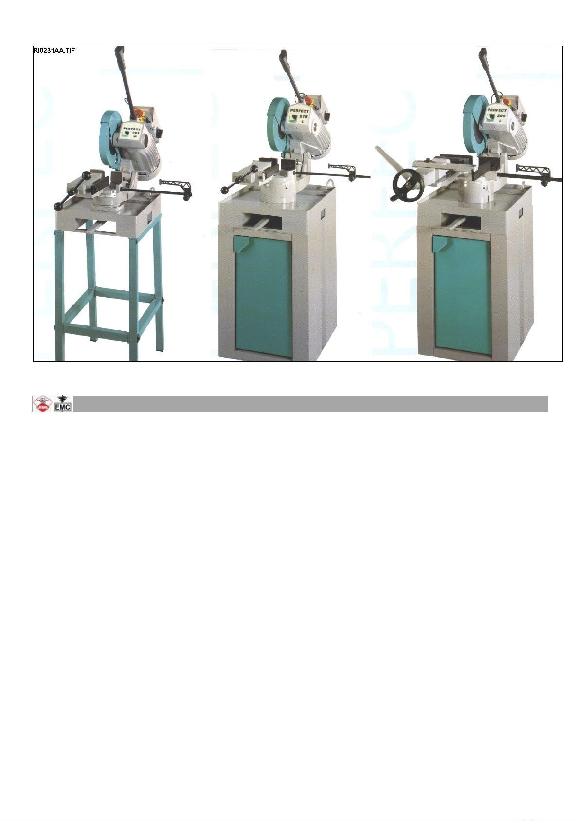
The machine can be placed on any working table ( if the structure guarantees a good stability and safety during the use)
or can be mounted on a stand, purposely designed for the professional use.
In this last case the floor space , the distances and the sources of energy are indicated in the included drawing RI0047.
It is recommended to level the work table also in a roughly way. This avoids that the material to cut could move, or the
machine could loose the stability.If the use in a definite place is foreseen ( fixed installation ).By using the screws and
nuts (NOT SUPPLIED) we suggest put in the little feet holes to FIX the machine to the floor .
The included electrical schemes reproduces the necessary details to arrange the connections, to be
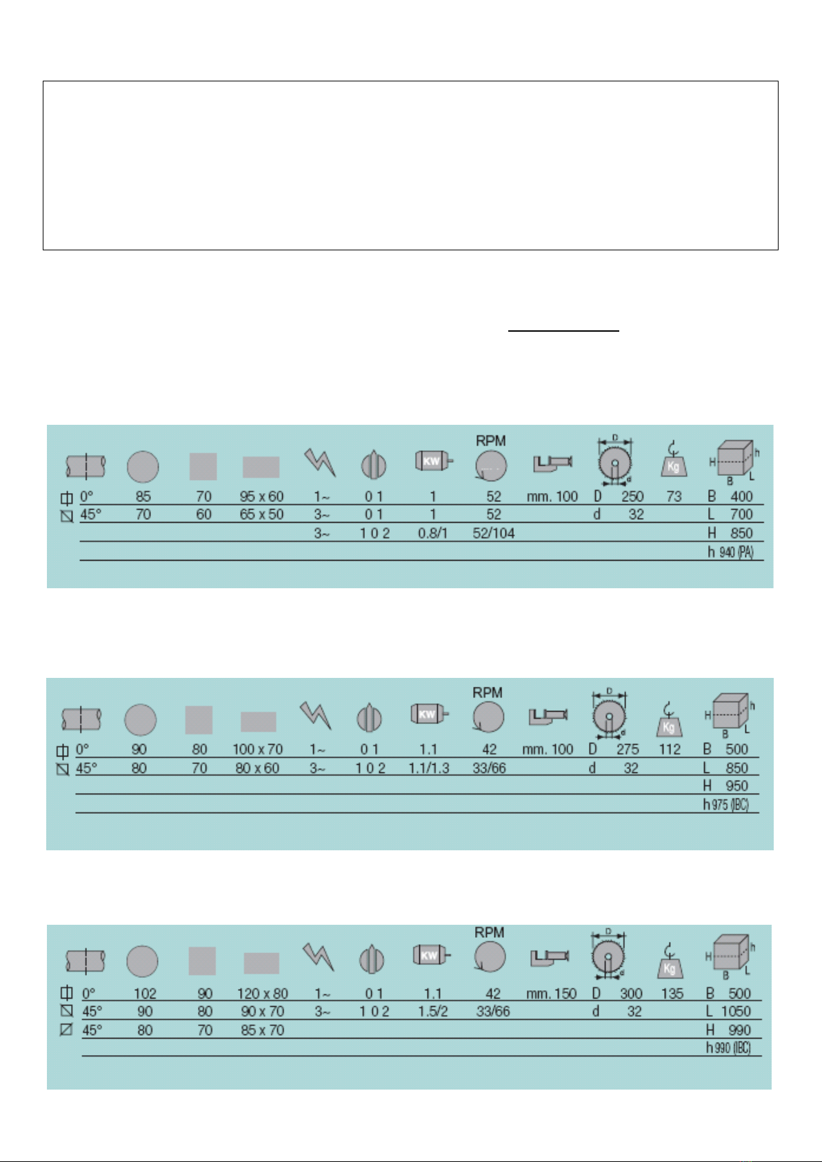
predisposed for 2 Kw power request, (Perfect 300 and 275) or 1,5 Kw for Perfect 250..
At the top of the supplying cables it is necessary to set up a sectionalizing device provided with a protection .
. Earthing of all the electric parts with a dedicated GREEN/YELLOW wire, connected with a TN system to the supply
cable. A supplementary earthing point –indicated with PE –can be located on the metallic structure of the machine
E.M.C. Electromagnetic noise
This machine has been foreseen for industrial and not for household use. In the event that should be electromagnetic
interferences the user is responsable for solving the problem together with the technical assistance of the manufacturer.
Before installing the machine the user must take into account possible electromagnetic problems of the working area. In
particular we suggest to install the plant away from:
- signalling, control and telephone cables;
- radiotelevision transmitters and receivers;
- computers or controlling and measuring instruments;
- safety and protection devices.
The electric supply cable must be kept as short as possible, well right and
without wires.
The covers, the door and the frame must be suitably closed when the plant is operating.
Under no circumstances the plant must be modified except for adjusting and
changing established by the manifacturer. Follow the maintenance schedule.
8 –TRANSPORT & LIFTING
For the transport of the machine only the methods indicated below are possible. However, be sure that the means of
transport snd lifting are able to stand the machine's weight and its packing (about 150 Kg):
WARNING
The personnel in charge of loading, unloading and moving the machines should use protective gloves.
WARNING
When lifting or moving the machine, or a part of it, take care of clearing the operations area of the people, considering
also an appropriate safety area around it, so as to avoid any risks of injuring people or damaging things located nearly.
Special packings –wooden crate , wooden case –may be predisposed on request, by charge.
ALL THE OPERATIONS THAT INVOLVE MOVING THE MACHINE MUST BE CONDUCTED WHILE RESPECTING
THE FOLLOWING BASIC RULES:

TRADUCTION OF THE ORIGINAL USER INSTRUCTIONS
PERFECT 250-275-300eng ED.2010 rev.00
16/40
+ When moving the machine, an appropriate means has to be used, with a loading capacity higher than the weight to
lift, which is indicated on the machine.
+ When choosing and then using equipment such as ropes, chains or lifting belts, be careful about their geometry
during the lifting and about the consequent actual loading capacity.
+ The machine is structured so as to offer lifting points, which are appropriately indicated and will have to be used for
lifting it.
+ In case the lifting belts touch parts of the machine, nylon belts are required; ropes or chains wrapped with jute or
clean covering can also be used. A great care is necessary while slinging and moving the machine in order to
hinder damages.
+ All operations have to be conducted with graduality, so as to avoid jolts and dangerous situations.
+ The person in charge of the operations has to make sure that all the national, local and company norms in
reference to injury prevention and work safety are respected.
+ Onr or more areas for material storage have to be identified.
After unpacking , take out the possible present lockings in agreement with the little locking feet.
Use a belt to lift up the machine, pass the belt under the joint of the cutting unit and then pass the belt round the fixed
part of the vice. Joint the ends of the belt in an only hook.
The weight is shown on the identification label of the packing, the weight is also wroten in the technical data of the
manual.
Make sure that lifting tools are proper for the weight and that the moving is correctly made without unbalancing the
machine.
Do not remove the locking bracket between the vice and the reducer head before positioning the machine in the using
place, if not, the cutting unit can move because of the springs fixed at the back side.
In case of following manipulations, the machine should be displaced with the saw head completely down and FIXED to
the base or the vice of machine. Fix also the front lever protruding from the base, to avoir head rotation.
9 - FITTINGS ASSEMBLING
.The informations for the installation are supplied together to the same fitting, but we hereby include a little working
description
Bar support WS - It is a simple and economic device to get alligned the bar to cut as regards to the vice. Weight
kg.80, adjusting height from 780 to 1150 mm.
Double closing vice - for models PERFECT 300 and PERFECT 275 only - It allows to lock from both sides of the
blade, the material that has to be cut. It avoids the forming of the burr and the unexpected detachment of the piece after
the cutting.
Note that t he standard vice already has an anti-burr device.
Pneumatic closing vice - for models PERFECT 300 only - the opening / closing is synchronized with the up / down
movement of the cutting unit. Note that the motor starting is allowed only if the vice is in closing conditions.
IBC Floor Stand - for models PERFECT 300, PERFECT 275 only . It allows to have the machine at the right height . It
is possible to fix the machine on the floor if necessary .
MCP Trolley - for models PERFECT 300, PERFECT 275 only - It allows to have the machine at the right height and to
displace it comfortably because of its anti-upsetting wheels .
Pedestal - type PA for PERFECT 250 - it is a simple and economic support that allows to have the machine at the
right height . It is supplied in a assembling box.
Adjustable bar stop - It is fixed at the right side; it is suitable to make cuts of the same lenght.

TRADUCTION OF THE ORIGINAL USER INSTRUCTIONS
PERFECT 250-275-300eng ED.2010 rev.00
17/40
10 - BLADE CHOICE
In this paragraph we suggest the type of blade to use for cutting and the material that must be worked. To get the best
performance from this machine it is necessary to understand the right applications of the used tools and what you have
not to do with them.
The blade you have to use must have the following dimensions (in mm.):
overall diameter = 300 max./250 min. ( for PERFECT 300 )
overall diameter = 275 max./225 min. ( for PERFECT 275 )
overall diameter = 250 max./200 min. ( for PERFECT 250 )
hole diameter = 32
thickness = 2 or 2,5
2 holes for the driving pin = d.10 x 63 or d. 12 x 64
P.S. You can get the maximum cutting sizes by using the blade of maximum diameter.
For making a right cut it is also necessary to establish the pitch ( t ) or the suitable number of teeth ( z ). The
blade must usually have the toothing as follows:
- close toothing (little teeth) for cutting thin materials, tubular and profiles.
- thin toothing (big teeth) for cutting solid materials or pieces that need a long piece of blade (for example the central
part of a “U” profile ), or more soft materials as aluminium, copper, soft bronze.
By choosing the right one you can avoid a lot of working errors and you can get a good blade penetration and the
necessary space for the chips.
If you cut more pieces at the same time, you must consider them as one piece (that is you have to consider the
global size).
The enclosed table shows the necessary information for a right choice. It can also be updated or changed by the
user according to his personal experiences.

TRADUCTION OF THE ORIGINAL USER INSTRUCTIONS
PERFECT 250-275-300eng ED.2010 rev.00
18/40

TRADUCTION OF THE ORIGINAL USER INSTRUCTIONS
PERFECT 250-275-300eng ED.2010 rev.00
19/40
11. INSTRUCTIONS FOR USE AND WARNINGS
MANUAL MODEL
11.1 - This machine is designed and manufactured so as to be safely used by the operator,provided that it is
properly operated . No protections will ever suffice if the operator does not work with due caution, does
not make sure that the machine is in top operating conditions and does not follow the instructions
below.
You must remember that the machine is designed to CUT METALS with a sharp tool, and you are
responsible to see that it is operated in a SAFE and CORRECT manner.
1. make sure that the machine is properly installed and electrical installation is proper.
2. be sure you are familiar with all operating, safety, and applications information before running this
saw.
3. see that all who operate this machine are properly trained and fully aware of all safety practices.
4. do not expose yourself or other people to any risk.
5. insist on proper personal protective equipment and practices.
6. maintain all factory-installed SAFETY DEVICES and make sure that these are never removed or
altered or restricted in any way.
7. the operator must have a safe and organized work area with suitable light and operating room.
8. the whole equipment has to be correctly and constantly maintained and inspected on a regular basis.
9. never use tools with different features from those for which the machine is designed for.
10.never use this machine to cut material bigger than the cutting capacity.
11. keep the cutting area clear of tools or other loose objects.
12. never operate the saw unless all protections are in place.
13. NEVER WEAR loose clothing, long sleeves, large gloves, jewelry, or any other items that may be
trapped into a part of the equipment. Confine long hair.
14. always disconnect the power at source when performing maintenance or making adjustments.
15. never insert hands or arms into or near the cutting area while machine is running.
16. properly clamp the material in the vice and never hold it with your hands.
17. support suitably the bar on both sides of the machine to prevent falling.
We recommend to connect an unloading table in case the cutting length of the material is longer than the distance
between the blade and the right edge of the saw.
18. when cutting very short pieces, make sure they do not jam into the blade.
19. if the blade becomes jammed, turn immediately off the motor, then move the cutting unit to the
CUTTING START position. If this is not possible, open the vice and move the piece, check that the blade
or teeth are not broken, if so replace it.
20. never change the working conditions when cutting, use a controlled downfeed force
21. do not move the saw while cutting and avoid its instability.
22. wear personal safety equipment, if required for a safe operation.
ALWAYS OPERATE THE MACHINE SAFELY, USING COMMON SENSE AND ALERTNESS

TRADUCTION OF THE ORIGINAL USER INSTRUCTIONS
PERFECT 250-275-300eng ED.2010 rev.00
20/40
On some parts of the machine there are some stickers which warn about the safety measures that have to be taken by
the operator who runs it. Their meaning (easy to understand) is indicated in the following chart

TRADUCTION OF THE ORIGINAL USER INSTRUCTIONS
PERFECT 250-275-300eng ED.2010 rev.00
21/40
11.2 - OPERATOR’S SAFETY
This section illustrates the safety protections applied on the saw, according to the current legislation in
the field of safety.
PERFECT MANUAL SAWING MACHINES with start/stop push-button in the control grip.
On these models the presence of the emergency stop push-button, like thus specific in the European Norm EN13898,
is not demanded.
This norm of September 2003, concerning bandsaws and circular saws, confirms what specified previously in
the norms EN 418, EN 60204, prEN13898.
11.2.1. ELECTRIC EQUIPMENT –Norm EN 60204-01
. Electric board closed with screws –the general switch is the combination plug & socket along the
alimentation suplly line.
. Marking of the electric components used, according to the indications on the electric scheme
. Control circuit with 24V tension –Control transformer with fuses on input and output
. Earthing of all electric parts with a dedicated GREEN/YELLOW wire, connected with a TN system to the
supply cable. A supplementary earthing point –indicated with PE –can be located on the metallic
structure of the machine.
. Minimum tension coil that prevents accidental restarting after a lack of tension(for some versions)
. Protection from overloads and high temperature thanks to bimetal thermo-protectors placed directly
into the blade motor
11.2.2 –PROTECTION AGAINST ACCIDENTAL CONTACTS
. Complete metallic protection of the blade and the blade shaft.
. Forward metallic moving guard, fixed to the main blade guard. It assures the coverage of the blade in
every position, except for the stretch of blade which makes the cut.
Positioning of the saw blade thanks to the control grip lever, equipped with a start/stop button, in order
to limit the width of the danger area to the stretch of blade strictly necessary for the cut.
. Pneumatic clamping vice ( if supplied) with a maximum stroke of 5 mm, according to the norms on
automatic closing
. Guard extended to both sides which retains the coolant used during the cut, preventing its spilling on
the floor
. Parts of the machine with suitably chamfered or rounded angles
.
112.3. LIGHTING OF THE WORKING AREA
An inadequate lighting can cause accidents to the operator, who consequently needs a suited lighting in
the working area. In case of a lack of precise indications (for example, norm ISO 8995) for special
areas, we advise to supply a lighting equal to 750 LUX.

TRADUCTION OF THE ORIGINAL USER INSTRUCTIONS
PERFECT 250-275-300eng ED.2010 rev.00
22/40
12 - MACHINE DESCRIPTION, E.C. SAFETY NORMS, SUGGESTIONS FOR USE
Manual disc sawing machine . The head swivels from 45 deg. right to 45 deg. left ( from 0° to 45 ° left only, the models
PERFECT 275 and PERFECT 250 ) of metal profiles and solids.
The cutting unit swivels round a cylindrical pin- at horizontal axis - with the possibility to adjust the shake.
All manual works consist of : locking material, approaching and cutting , tool return, unlocking material and bar
displacement for a new cut.
The starting of the tool is controled by a pushbutton placed inside the control level.
The switch is protected by a guard against accidental starts, the working voltage is 24V.
It is not suitable to cut wood and assimilated materials (cfr. D.M. 2006/42/CE, enclosure I, paragraph 2.3).
For making mitre cuttings it is necessary to rotate manually the saw head to the left/right too.
From the position of work, just opposite the frontal vice, the operator has the possibility to use the commands and to
control the good working of the machine.
In the following paragraphs you will find all information for using the machine in the best way and for a very long time.
In designing and manufacturing this machine, we have considered the requirements of the Machine Directive
(2006/42/CE and so on..), important document valid in all E.E.C. Countries. Furthermore we have considered the norms
as type A in the case that specifications of type C are not available. The applied safety norms are mentioned in the
included compliance declaration.
The choice and the use of the parts have been made by considering the conditions of use and the long machine life.
12.1 - APPENDIX FOR E.M.C.
The structure of this machine complies to the protection requirements of the EEC Directives 2004/108/CE 89/336/EEC,
92/31/EEC and 93/68/EEC in terms of Electromagnetic Compatibility (E.M.C.).
It especially abides by the technical prescriptions of the norms EN 55011 and EN 50082-2, and it is fit to be used in
industrial environments and not in residential ones.
13 - MACHINE SETTING FOR STARTING
Verify that the machine has not clear damages or faults and check upon the standard equipment that includes the tools,
fittings to carry out some adjustments, using and maintenance handbook.
In case the machine is supplied with additional equipment make sure that it is adaptable to the machine.
Point in good time the possible damages or faults to the reseller or to the service staff before the machine starting.
Remove the lock flask between saw frame and base, and insert in the hole of the head, the rod with the starting device.
Lock it with the upper grub screw ( in the model PERFECT 250 also unscrew the threaded bar , in its place screw the
control rod, guide it and lock it with the nut ). Connect the switch of the cable projecting from the rod in the plug placed
on the control device. Place to the right side the length stop device, as per above pictures.

TRADUCTION OF THE ORIGINAL USER INSTRUCTIONS
PERFECT 250-275-300eng ED.2010 rev.00
23/40
By using a non-filamentous cloth or paper remove the protective sustances placed on the surfaces , for the protection
during the moving and transit and please check that there is no rust on the metallic parts.
In case of using compressed air jet always wear proper eye protection.
The parts in motion ( band guides, trolleys, pivots, bearing support, bearing disc etc. ) are already lubricated.
The possible pneumatic installation ( for ex. for the vice of the model PERFECT 300 ) is ready to start.
13.1 - COOLING AND LUBRICATION PLANT
Prepare the lubricant in a case by mixing cutting oil and water in the proportion 1/10, 1/15 or according to the
instructions of the supplier ( a quantity of 10 l about also allows to make the fill up).
Pour out some lubricant into the tank through the loading hole until to fill it, or directly on the loading table; keep that the
coolant doesnot come out the base. The suction pipe passes by a filter ( washable and/or replaceable ) and it is
connected to the meccanic pump which is drived by the electrical motor . When the machine is new, it is necessary to
idle the motor to suction the coolant until the delivery nozzle .
After cooling the blade , some of the coolant is directed with the chips to the tank to be filtered and used again.
- 13.2 - PNEUMATIC CONNECTION ( if a pneumatic vice is fitted )
It is suitable to connect the machine to an installation supplied at least with :a condensate discharger, filter and
reducer gear to stabilize the pressure to 6/8 BAR . It is recommended to reduce again the in the case you work with
material capable of being deformed .
13.3 - ELECTRICAL CONNECTION
Verify that the voltage and the power frequency are compatible with numbers reported in the technical data plate ( It is
placed on the right side of the head column) a difference over 10% causes some working unevenness more or less
manifested.
Connect the switch to a suitable socket or replace it with that of normal use( in the case the switch must be
replaced , the work must be done by an electrician ). The phasing performed by the manufacturer allows to get
a rotation of all motors by connecting the wires in the following order L1=R, L2=S, L3=T, anyhow check as
follows : ( with compressed air connected, is necessary, pressure not lower than 2 BAR ).
a) turn on the main switch placed on the electrical control device to give current to the installation ( for some models
only ).
b) turn on 1 the motor speed selector ( for models equipped with 3 phase motor at 2 speeds only ).
c) push the button placed inside the handle of the control lever.
d) be sure that the spindle turns in the sense shown by the PRINTED ARROW ON THE PROTECTION GUARD -
pos.11/RI0130-.
If not, turn off the machine, disconnect the feeding plug, reverse the connection of the both line connection wire,
excluding the green/yellow cable of grounding and start again from point a).
Attention : ( for some versions only ) the starting of the motor of the machine equipped with pneumatic vice is
only possible if the pneumatic vice is rightly connected to the pneumatic installation and the vice is closed (
by lowering the head ) .
e) Be sure that coolant is sucked in by the tank and it arrives in the cutting area, if not please control the cock position.
f) stop the working by releasing the button placed inside the handle.

TRADUCTION OF THE ORIGINAL USER INSTRUCTIONS
PERFECT 250-275-300eng ED.2010 rev.00
24/40
- 14 - BLADE ASSEMBLING
Choose the blade features by following the instructions of the previous list. Position the cutting unit up ( rest )
Turn back the movable protection guard ( inside the fixed protection guard ) to have the spindle .Follow as
recommended for each model by remembering that :
a) the closing spindle screw has the thread on left sense
b) the teeth of the blade must be oriented to the direction of the arrow placed on the protection guard .
c) before tightening the spindle screw, wheel back the blade to cancel the remaining shake between the driving pin and
the blade holes.
d) the models PERFECT 300 and PERFECT 275 has a clutch that is adjusted with the same screw of the
spindle ; it is necessary to clean the protective oil from the 4 tempered rings that settle the clutch before
mounting the blade.
e) rightly connect the bucket spring -pos.2- on the screw- pos.1 - as shown by the dr.RI0118.
NEVER mount the cup spring REVERSED , but always with the WIDEST part directed TOWARDS THE BLADE.
14.1 -MODEL PERFECT 300, see the dr. RI0130 :
Remove the screw -pos.9 and completely wheel the part-pos.10 - inside the protection guard-pos.11 -, by keeping the
little rod up -pos.12-. Through the central hole- pos.13- it is possible unscrew the screw of the spindle.
Remove it, also disconnect the 4 parts that settle the clutch and degrase them;
then with reference to the dr.RI0118 :
mount again the parts -pos.5 and 6-, insert the blade in the shown sense and agree the holes with those of the already
mounted flange. Couple the parts -pos.3 and 4- and connect them with the end of the spindle, by agreeing the driving
pins with the holes of the blade . Mount again the bucket spring-pos.2- and tight the screw-pos.1- to lock the blade.
Replace the start position of the protection guard and lock it.
14.2 - MODEL PERFECT 275 , see the dr. RI0155
Unscrew 1 turn ab. the screw -pos1- and turn completely the movable part -pos.2- into the fixed blade guard -pos.3.
Unscrew of 2 turns ab. The front screw -pos. 6- that fix the complete blade guard.
To reach the spindle it is necessary rotate to the back this cover blade, around the pivot pin -pos.5-.
Now it is possible unscrew the screw of the spindle.

TRADUCTION OF THE ORIGINAL USER INSTRUCTIONS
PERFECT 250-275-300eng ED.2010 rev.00
25/40
Remove it, also disconnect the 4 parts that settle the clutch and degrase them;
then with reference to the dr.RI0118 :
mount again the parts -pos.5 and 6-, insert the blade in the shown sense and agree the holes with those of the already
mounted flange. Couple the parts -pos.3 and 4- and connect them with the end of the spindle, by agreeing the driving
pins with the holes of the blade . Mount again the bucket spring-pos.2- and tight the screw-pos.1- to lock the blade.
Reset the initial position of the protection guard and lock it.
14.3 - MODEL PERFECT 250 , see dr. RI0155
Unscrew of 1 turn ab. the screw -pos1- and turn completely the movable part -pos.2- into the fixed blade guard -pos.3.
Unscrew of 2 turns ab. The side screw –pos.4- that fix the complete blade guard.
To reach the spindle it is necessary rotate to the back this cover blade around this screw. (pay attention to the little pin
near the spindle that fix the whole carter to the saw head.
Then, with reference to the dr.RI0156, is possible unscrew the screw of the spindle -pos.1- and remove it with the
closing flange-pos.2- and clean them; insert the blade in the shown sense and agree the holes with those of the
already mounted flange. Mount the closing flange at the end of the spindle, by agreeing the driving pins with the holes
of the blade . Mount again the screw -pos.1- and tight it. to lock the blade.
Reset the initial position of the protection guard and lock it.
-15 -STARTING
The sectionalising devices of the outer energy are :
On the feeding cable there is the plug + plug socket , and for models with pneumatic vice only, there is the connection
for compressed air placed at the back of the machine.
The control panel, drawing RI0094-, placed in front of the operator includes :
The controls that can be operated by the operator are :
1- The main switch( only for special models )-pos.1/RI0128-, equipped with releasing device for drop of current.
2- Motor speed selector .-pos.2/dr.RI0128 –( only for 2 speed machine).
3- Plug + socket for the safety low voltage (24V) control-pos.3/dr.RI0128 -.
Other keys are placed in other accessible parts:
4- Handle with starting up button-pos.4/dr.RI0128-.
5- Manual opening/closing of frontal vice -pos.5/dr.RI0128-.
6- Unlocking / locking of the rotation of the working table for inclined cuts-pos.1/dr.RI0129-.
This manual suits for next models
2
Table of contents
Other IMET Saw manuals
Popular Saw manuals by other brands

Skil
Skil 5740 Original instructions

Wacker Neuson
Wacker Neuson BTS 635s Operator's manual

HIKOKI
HIKOKI C 3607DWA Handling instructions

Matco Tools
Matco Tools RL1314A Operating instructions, warning information, parts breakdown

GÜDE
GÜDE GTKS 2200 PRO Translation of the original instructions

Roto Zip Tool
Roto Zip Tool SCS02 owner's manual