7 - INSTALLATION
The machine can work according to the parameters provided by the manufacturer if it is rightly installed and the
minimum requirements are observed, as follows :
- Machine must be used indoor and with temperatures from +5 to + 40 ° C.
- The relative humidity of the environment must not go over 95%.
- The nominal value of the voltage of electric energy must be between + - 10 and the frequency of the nominal value
must be between + - 2%.
The floor must have good characteristiques of capacity and level.
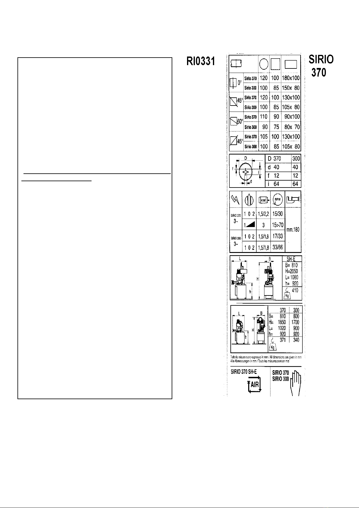
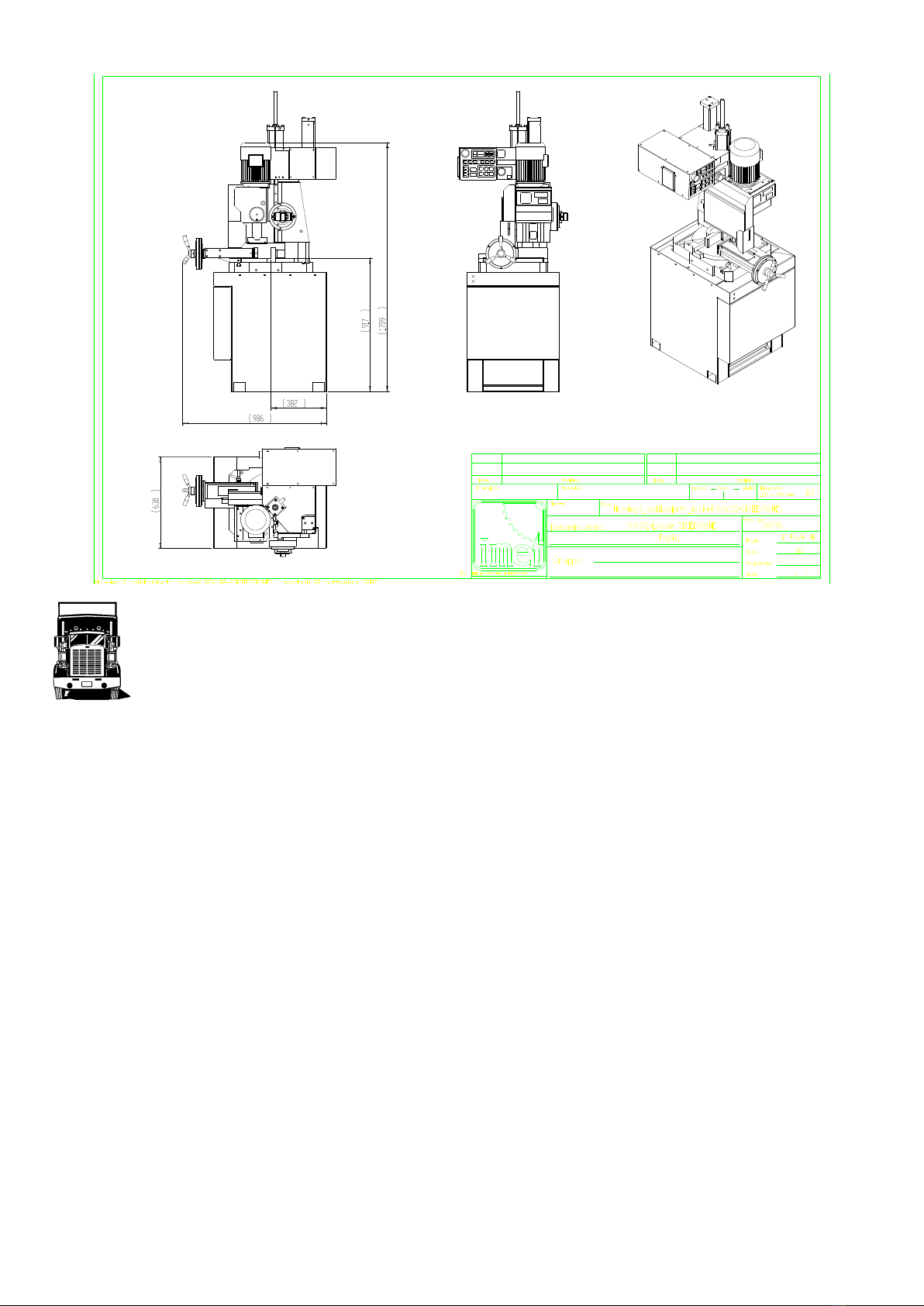
Floor space, operator position and working area are indicated in the included drawing that concerns the machine only
without fittings as optional.
Work table must be leveled: by using the screws and nuts (NOT SUPPLIED) put in the little feet holes to FIX the
machine to the floor .
The included electrical schemes reproduces the necessary details to arrange the connections, to be
predisposed for 5 KW power request,.
. Earthing of all the electric parts with a dedicated GREEN/YELLOW wire, connected with a TN system to the supply
cable. A supplementary earthing point –indicated with PE –can be located on the metallic structure of the machine.
N.B.
Be careful with cables protruding from upper part of machine when you are lifting it.
Fix between them the machine and the floor stand by using the 4 socket screws supplied together to the current
fittings ( do not use those employed for the packing ). The nuts are already in the using position.
The tank and the electropump must be desplaced from the base and placed inside the floor stand trough the back
opening; to do this , it is necessary to remove the chip tray taking out it from the front side of base.
The cables that come out from the back side of the machine must be inserted in the floor stand; then the supply cable
must be inserted ( form inside to outside ) in the cable-nut ( and locked ) before the connection to the line.
Connect the cooling pipe to the cock placed on the carter of the machine.
If there are other parts as pneumatic vice they must be connected to the customer’s pipe of compressed air :
vice with pressure reducer device - placed into the floor stand - connect pipe to the free connection of this reducer
device and connect the pipe from vice to the other connection of this reducer also.
7.1 - DIFFERENTIAL PROTECTION
For the connection of the differential protection on the power supply line it is necessary to use switches with a
threshold of interference on the power dissipation of not less than 300 mA (size 0.3 A or higher is
recommended), having possibly time adjustment availability (0>1.5 sec).
E.M.C. Electromagnetic noise
This machine has been foreseen for industrial and not for household use. In the event that should be electromagnetic
interferences the user is responsable for solving the problem together with the technical assistance of the manufacturer.
Before installing the machine the user must take into account possible electromagnetic problems of the working area. In
particular we suggest to install the plant away from:
- signalling, control and telephone cables;
- radiotelevision transmitters and receivers;
- computers or controlling and measuring instruments;
- safety and protection devices.
The electric supply cable must be kept as short as possible, well right and
without wires.
The covers, the door and the frame must be suitably closed when the plant is operating.
Under no circumstances the plant must be modified except for adjusting and
changing established by the manifacturer. Follow the maintenance schedule.