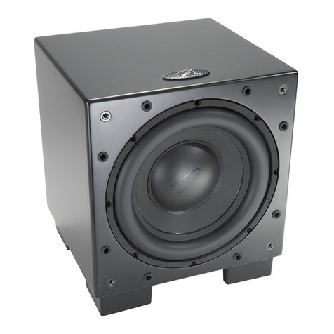
IMG STAGE LINE PSUB-215 User manual

AKTIVE SUBWOOFER-BOX
ACTIVE SUBWOOFER SYSTEM
ENCEINTE SUBWOOFER ACTIVE
CASSA SUBWOOFER ATTIVA
BEDIENUNGSANLEITUNG • INSTRUCTION MANUAL
MODE D’EMPLOI • ISTRUZIONI PER L’USO • GEBRUIKSAANWIJZING
MANUAL DE INSTRUCCIONES • INSTRUKCJA OBSŁUGI
SIKKERHEDSOPLYSNINGER • SÄKERHETSFÖRESKRIFTER • TURVALLISUUDESTA
PSUB-215 Best.-Nr. 24.8470

2
wwwwww..iimmggssttaaggeelliinnee..ccoomm
Ennen kytkemistä …
Toivomme Sinulle paljon miellyttäviä hetkiä
uuden “img Stage Line” laitteen kanssa. Ennen
laitteen käyttöä pyydämme Sinua huolellisesti
tutustumaan turvallisuusohjeisiin. Näin vältyt
vahingoilta, joita virheellinen laitteen käyttö saat-
taa aiheuttaa. Ole hyvä ja säilytä käyttöohjeet
myöhempää tarvetta varten.
Turvallisuusohjeet löytyvät sivulta 19.
FIN
Bevor Sie einschalten …
Wir wünschen Ihnen viel Spaß mit Ihrem neuen
Gerät von „img Stage Line“. Bitte lesen Sie diese
Bedienungsanleitung vor dem Betrieb gründlich
durch. Nur so lernen Sie alle Funktionsmöglich-
keiten kennen, vermeiden Fehlbedienungen und
schützen sich und Ihr Gerät vor eventuellen Schä-
den durch unsachgemäßen Gebrauch. Heben
Sie die Anleitung für ein späteres Nachlesen auf.
Der deutsche Text beginnt auf der Seite 4.
D
A
CH
Avant toute installation …
Nous vous souhaitons beaucoup de plaisir à uti-
liser cet appareil “img Stage Line”. Lisez ce mode
d'emploi entièrement avant toute utilisation. Uni-
quement ainsi, vous pourrez apprendre l’en-
semble des possibilités de fonctionnement de
l’appareil, éviter toute manipulation erronée et
vous protéger, ainsi que l’appareil, de dommages
éventuels engendrés par une utilisation inadap-
tée. Conservez la notice pour pouvoir vous y
reporter ultérieurement.
La version française se trouve page 8.
Antes de la utilización …
Le deseamos una buena utilización para su nuevo
aparato “img Stage Line”. Por favor, lea estas
instrucciones de uso atentamente antes de hacer
funcionar el aparato. De esta manera conocerá
todas las funciones de la unidad, se prevendrán
errores de operación, usted y el aparato estarán
protegidos en contra de todo daño causado por
un uso inadecuado. Por favor, guarde las instruc-
ciones para una futura utilización.
El texto en español empieza en la página 14.
Før du tænder …
God fornøjelse med dit nye “img Stage Line” pro-
dukt. Læs venligst sikkerhedsanvisningen nøje,
før du tager produktet i brug. Dette hjælper dig
med at beskytte produktet mod ukorrekt ibrug-
tagning. Gem venligst denne betjeningsvejled-
ning til senere brug.
Du finder sikkerhedsanvisningen på side 18.
DK
Before switching on …
We wish you much pleasure with your new “img
Stage Line” unit. Please read these operating
instructions carefully prior to operating the unit.
Thus, you will get to know all functions of the unit,
operating errors will be prevented, and yourself
and the unit will be protected against any
damage caused by improper use. Please keep
the operating instructions for later use.
The English text starts on page 6.
Voor u inschakelt …
Wij wensen u veel plezier met uw nieuwe appa-
raat van “img Stage Line”. Lees deze gebruikers-
handleiding grondig door, alvorens het apparaat
in gebruik te nemen. Alleen zo leert u alle func-
ties kennen, vermijdt u foutieve bediening en
behoedt u zichzelf en het apparaat voor even-
tuele schade door ondeskundig gebruik. Bewaar
de handleiding voor latere raadpleging.
De Nederlandstalige tekst vindt u op pagina 12.
E
GB
I
S
Prima di accendere …
Vi auguriamo buon divertimento con il vostro
nuovo apparecchio di “img Stage Line”. Leggete
attentamente le istruzioni prima di mettere in fun-
zione l'apparecchio. Solo così potete conoscere
tutte le funzionalità, evitare comandi sbagliati e
proteggere voi stessi e l'apparecchio da eventu-
ali danni in seguito ad un uso improprio. Conser-
vate le istruzioni per poterle consultare anche in
futuro.
Il testo italiano inizia a pagina 10.
Innan du slår på enheten
Vi önskar dig mycket glädje med din nya “img
Stage Line” produkt. Läs igenom säkerhetsföre-
skrifterna noga innan enheten tas i bruk. Detta
kan förhindra att problem eller fara för dig eller
enheten uppstår vid användning. Spara instruk-
tionerna för framtida användning.
Säkerhetsföreskrifterna återfinns på sidan 18.
F
B
CH
NL
B
Przed Uruchomieniem …
Życzymy zadowolenia z nowego produktu “img
Stage Line”. Dzięki tej instrukcji obsługi będą
państwo w stanie poznać wszystkie funkcje
tego urządzenia. Stosując się do instrukcji uni-
kną państwo błędów i ewentualnego uszkodze-
nia urządzenia na skutek nieprawidłowego
użytkowania. Prosimy zachować instrukcję.
Tekst polski zaczyna się na stronie 16.
PL

3
SUBSONIC
LINE OUT LINK
BALANCED
INPUT
BALANCED
LIMIT.
NORM.
PROT.
AMP. ON
SUBBOOST
+6 dB
BASS
LEVEL
0
BASS
PHASE
IN
PHASE
230 V~ / 50 Hz /900 VA
80
90
11
0
10
0
150
200
120
300
350
400
440
X-OVER
PHASE
LPF
HPF
T 4 AL
H
z
LINE OUT SAT
BALANCED
180
°
SERIAL-NO.
600 WMAX /400 WRMS
ACTIVE SUBWOOFER
SYSTEM
PSUB-215
–80
dB +20
dB 0180°
POWER
1
2
3
4
5678
9
11
12
13
14
10

D
A
CH
4
Bitte klappen Sie die Seite 3 heraus. Sie sehen
dann immer die beschriebenen Bedienelemente
und Anschlüsse.
1Übersicht der Bedienelemente und An-
schlüsse
1Lüfter
2Kontrollanzeigen
AMP. ON/PROT., leuchtet:
–grün als Betriebsanzeige
–rot, wenn die Schutzschaltung anspricht
a) für einige Sekunden direkt nach dem Ein-
schalten, dann wechselt sie auf Grün
b) permanent, wenn eine Betriebsstörung
oder ein Defekt des Gerätes vorliegt
LIMIT.:
leuchtet, wenn die integrierte Limiter-Schaltung
die Lautstärke beim Erreichen des maximalen,
noch unverzerrten Pegels begrenzt
NORM.:
leuchtet ab einer bestimmten Lautstärke im Takt
der Musik
3symmetrischer XLR-Durchschleifausgang, parallel
geschaltet zum Eingang INPUT (4), zum An-
schluss einer weiteren Aktivbox
4symmetrische Eingangsbuchse (kombinierte XLR-/
6,3-mm-Klinkenbuchse) für den Anschluss eines
Geräts mit Line-Ausgangspegel (z.B. CD-Spieler,
Mischpult)
5Taste SUBBOOST für eine Pegelanhebung im un-
teren Bassbereich; bei gedrückter Taste (LED da-
neben leuchtet) ist die Funktion eingeschaltet
6Taste PHASE zur Anpassung der Phasenlage
beim Einsatz mehrerer Lautsprechersysteme: bei
gedrückter Taste (LED daneben leuchtet) wird die
Phase des Eingangssignals um 180° gedreht
7Taste SUBSONIC zum Ein-/Ausschalten des Sub-
sonic-Filters (Hochpass): bei gedrückter Taste (LED
daneben leuchtet) ist das Filter zur Unterdrückung
tieffrequenter Störungen eingeschaltet
8Regler X-OVER für die Trennfrequenz (80–440Hz)
zwischen Subwoofer und Satellitenlautsprecher
9Regler BASS LEVEL für die Lautstärke des Sub-
woofers
10 Regler BASS PHASE für die Phasenlage des Sub-
woofers
11 symmetrische Ausgangsbuchse LINE OUT SAT
zum Anschluss eines aktiven Satellitenlautspre-
chers
12 Ein-/Ausschalter der aktiven Subwoofer-Box
13 Netzbuchse zum Anschluss an eine Steckdose
(230V~/50Hz) über das beiliegende Netzkabel
14 Halterung für die Netzsicherung;
eine durchgebrannte Sicherung nur durch eine
gleichen Typs ersetzen
2Hinweise für den sicheren Gebrauch
Das Gerät entspricht der Richtlinie 89/336/EWG für
elektromagnetische Verträglichkeit und der Nieder-
spannungsrichtlinie 73/23/EWG.
Beachten Sie auch unbedingt die folgenden Punkte:
●Verwenden Sie das Gerät nur im Innenbereich und
schützen Sie es vor Tropf- und Spritzwasser, hoher
Luftfeuchtigkeit und Hitze (zulässiger Einsatztempe-
raturbereich 0–40°C).
●Stellen Sie keine mit Flüssigkeit gefüllten Gefäße,
z.B. Trinkgläser, auf das Gerät.
●Die im Gerät entstehende Wärme muss durch Luft-
zirkulation abgegeben werden. Decken Sie die Lüf-
tungsöffnungen nicht ab.
●Nehmen Sie das Gerät nicht in Betrieb und ziehen
Sie sofort den Netzstecker aus der Steckdose,
1. wenn sichtbare Schäden am Gerät oder an der
Netzanschlussleitung vorhanden sind,
2. wenn nach einem Sturz oder Ähnlichem der Ver-
dacht auf einen Defekt besteht,
3. wenn Funktionsstörungen auftreten.
Lassen Sie das Gerät in jedem Fall in einer Fach-
werkstatt reparieren.
●Ziehen Sie den Netzstecker nie an der Zuleitung aus
der Steckdose, fassen Sie immer am Stecker an.
●Verwenden Sie für die Reinigung nur ein trockenes,
weiches Tuch, niemals Wasser oder Chemikalien.
●Wird das Gerät zweckentfremdet, falsch ange-
schlossen, nicht richtig bedient oder nicht fach-
gerecht repariert, kann keine Haftung für daraus
resultierende Sach- oder Personenschäden und
keine Garantie für das Gerät übernommen werden.
3Einsatzmöglichkeiten
Die aktive Subwoofer-Box PSUB-215 eignet sich opti-
mal zur Bass-Unterstützung der Aktiv-Lautsprecher-
boxen PAK-212 und PAK-215 von „img Stage Line“
sowie anderer PA-Lautsprecher. Der interne Verstär-
ker gibt eine Sinusleistung von 400W an den hoch-
wertigen 38-cm-Tieftöner ab.
An den symmetrischen Eingang kann ein Gerät mit
Line-Ausgangspegel (z.B. Mischpult, CD-Spieler) an-
geschlossen werden. Der symmetrische Satelliten-
ausgang stellt das Signal (ohne Bassanteil) für die
Satelliten-Lautsprecherbox zur Verfügung. An den
Durchschleifausgang lässt sich eine weitere Aktivbox
anschließen.
Soll das Gerät endgültig aus dem Betrieb
genommen werden, übergeben Sie es zur
umweltgerechten Entsorgung einem örtli-
chen Recyclingbetrieb.
WARNUNG Das Gerät wird mit lebensgefährlicher
Netzspannung (230V~) versorgt. Neh-
men Sie deshalb niemals selbst Eingriffe
am Gerät vor und stecken Sie nichts
durch die Lüftungsöffnungen! Es besteht
die Gefahr eines elektrischen Schlages.

D
A
CH
5
4Aufstellung und Anschluss
1) Die Box frei auf dem Boden aufstellen. Über der
Box lässt sich in einem bestimmten Abstand ein
Satellitenlautsprecher anbringen. Dazu ein Boxen-
Zwischenstück (z.B. aus der PAST-Serie von „img
Stage Line“) in die Stativhülse auf der Oberseite
des PSUB-215 stecken und darauf den Satelliten-
lautsprecher.
2) Als Signalquelle ein Audiogerät mit Line-Ausgangs-
pegel (z.B. Mischpult, CD-Spieler, MD- oder Kas-
settenrecorder) anschließen. Den Monoausgang
oder einen Stereokanal der Signalquelle mit der
symmetrischen Eingangsbuchse INPUT (4) verbin-
den. (Den anderen Stereokanal auf eine zweite
Aktivbox geben.)
3) Am symmetrischen XLR-Ausgang LINE OUT LINK
(3) steht das durchgeschleifte Eingangssignal zur
Verfügung. Hier kann der Eingang einer weiteren
Aktivbox angeschlossen werden.
4) Die zugehörige aktive Satelliten-Lautsprecherbox
an den symmetrischen Ausgang LINE OUT SAT
(11) anschließen oder eine passive Sat.-Lautspre-
cherbox über einen entsprechenden Verstärker.
5) Zuletzt das beiliegende Netzkabel an die Netz-
buchse (13) anschließen und mit einer Steckdose
(230V~/50Hz) verbinden.
5Bedienung
Alle Einstellungen und Klangbeurteilungen können nur
in Verbindung mit dem Satellitenlautsprecher erfolgen.
Der Klang sollte am endgültigen Hörplatz beurteilt und
durch eine zweite Person am Aktiv-Subwoofer nach
Anweisung optimal angepasst werden.
1) Mit dem Regler X-OVER (8) die Trennfrequenz
zwischen Subwoofer und Satellitenlautsprecher
einstellen (je niedriger die Trennfrequenz, desto
schwerer die akustische Ortung des Subwoofers;
je höher die Trennfrequenz, desto stärker die Bass-
unterstützung). Zur Orientierung den Frequenzbe-
reich der Satellitenlautsprecher beachten.
2) Die angeschlossene Signalquelle einschalten.
3) Vor dem Einschalten des Subwoofers den Regler
BASS LEVEL (9) auf Null drehen, um Einschalt-
geräusche zu vermeiden. Dann den Subwoofer mit
dem Netzschalter POWER (12) einschalten: Die
obere Anzeige AMP. ON/PROT. (2) leuchtet nach
dem Einschalten für einige Sekunden rot (Schutz-
schaltung aktiviert, Gerät stumm geschaltet) und
wechselt dann auf Grün (Normalbetrieb).
4) Mit dem Regler BASS LEVEL die Lautstärke ein-
stellen. Ab einer bestimmten Lautstärke leuchtet
die untere Anzeige NORM. (2) im Takt der Musik.
Bei zu hohem Pegel leuchtet die mittlereAnzeige
LIMIT. (2), um anzuzeigen, dass die integrierte Limi-
ter-Schaltung aktiv ist. Die Limiter-Schaltung dient
zum Begrenzen des Signalpegels: Überschreitet
der Pegel einen definierten Maximalwert, wird er
von der Limiter-Schaltung auf diesen Wert herunter-
geregelt. Sollte dieAnzeige LIMIT. ständig leuchten,
den Lautstärkeregler entsprechend zurückdrehen.
5) Durch Drücken der Taste SUBBOOST (5) kann bei
Bedarf der untere Bassbereich angehoben werden.
Bei eingeschalteter Subboost-Funktion leuchtet die
LED neben der Taste.
6) Trittschall oder andere tieffrequente Störungen las-
sen sich durch Zuschalten des Subsonic-Filters
unterdrücken: Die Taste SUBSONIC (7) drücken.
Bei eingeschaltetem Filter leuchtet die LED neben
der Taste.
7) Bei der Aufstellung mehrerer Lautsprechersysteme
können die Schallwellen der Systeme am Hörplatz
eine unterschiedliche Phasenlage aufweisen, wo-
durch es zu unerwünschten Dämpfungen bestimm-
ter Frequenzen kommen kann. Um dies auszuglei-
chen, besitzt die Aktivbox einen Phasenumkehr-
schalter, die Taste PHASE (6), mit der sich die
Phase des Audiosignals um 180° drehen lässt.
Zuerst den Regler BASS PHASE (10) auf Null dre-
hen. Dann die beiden Stellungen der Taste PHASE
– gedrückt (LED daneben leuchtet) oder ausgera-
stet – ausprobieren und diejenige wählen, bei der
die Wiedergabe besser ist.
8) Die Phasenlage für den Subwoofer mit dem Regler
BASS PHASE einstellen. Diese Einstellung ist je
nach den akustischen Gegebenheiten stärker oder
schwächer wahrnehmbar. Am besten lässt sich die
Einstellung bei einem Musikstück mit einem E-Bass,
einem Kontrabass oder einer tiefen Bassstimme
vornehmen. Den Regler BASS PHASE auf lauteste
Basswiedergabe einstellen. Danach bei Bedarf den
Regler BASS LEVEL wieder etwas zurückdrehen.
9) Nach dem Betrieb das Gerät mit dem Schalter
POWER ausschalten.
6Technische Daten
Verstärkerleistung: . . . . . . . . . . . . . . . 400 WRMS, 600 WMAX
Frequenzbereich: . . . . . . . . . . . . . . . . 33 – 400 Hz
Eingang
Eingangsempfindlichkeit: . . . . . . . 75 mV (Line-Pegel)
Impedanz: . . . . . . . . . . . . . . . . . . . 20 kΩ
Anschluss: . . . . . . . . . . . . . . . . . . XLR/6,3-mm-Klinke, sym.
Ausgänge
LINE OUT LINK: . . . . . . . . . . . . . . durchgeschleiftes Eingangs-
signal; XLR, sym.
LINE OUT SAT: . . . . . . . . . . . . . . . Line-Signal für Satellitenlaut-
sprecher; XLR, sym.
Trennfrequenz: . . . . . . . . . . . . . . . . . . 80 – 440 Hz
Mittl. Schalldruck (1 W/1 m): . . . . . . . 97 dB
Max. Schalldruck: . . . . . . . . . . . . . . . . 123 dB
Einsatztemperatur: . . . . . . . . . . . . . . . 0 – 40 °C
Stromversorgung: . . . . . . . . . . . . . . . 230 V~/50 Hz/900 VA
Abmessungen, Gewicht: . . . . . . . . . . 515 x 540 x 580 mm, 4,5 kg
Änderungen vorbehalten.
VORSICHT Stellen Sie die Lautstärke nie sehr hoch
ein. Hohe Lautstärken können auf Dauer
das Gehör schädigen! Das menschliche
Ohr gewöhnt sich an sie und empfindet
sie nach einiger Zeit als nicht mehr so
hoch. Darum eine hohe Lautstärke nach
der Gewöhnung nicht weiter erhöhen.
Diese Bedienungsanleitung ist urheberrechtlich für
MONACOR®INTERNATIONAL GmbH & Co. KG geschützt.
Eine Reproduktion für eigene kommerzielle Zwecke – auch aus-
zugsweise – ist untersagt.

GB
6
Please unfold page 3. Then you can always see the
operating elements and connections described.
1Operating Elements and Connections
1Fan
2Indicating LEDs
AMP. ON/PROT., lights up:
–green as an operating indication
–red when the protective circuit responds
a) for some seconds directly after switching
on, then it will change to green
b) permanently in case of a failure or defect of
the unit
LIMIT.:
lights up when the integrated limiter circuit limits
the volume when reaching the maximum level
not yet distorted
NORM.:
lights up from a certain volume to the rhythm of
the music
3Balanced XLR feed-through output, connected in
parallel to the INPUT (4), to connect another active
speaker system
4Balanced input jack (combined XLR/6.3mm jack)
for connecting a unit with line output level (e.g. CD
player, mixer)
5Button SUBBOOST for a level boosting in the
lower bass range; with the button pressed (LED
next to it lights up), the function is switched on
6Button PHASE for matching the phase when using
several speaker systems: with the button pressed
(LED next to it lights up), the phase of the input sig-
nal is turned by 180°
7Button SUBSONIC for switching on/off the sub-
sonic filter (high pass): with the button pressed
(LED next to it lights up), the filter is switched on to
suppress low-frequency interference
8Control X-OVER for the crossover frequency (80–
440Hz) between the subwoofer and the satellite
speaker
9Control BASS LEVEL for the volume of the sub-
woofer
10 Control BASS PHASE for the phase of the sub-
woofer
11 Balanced output jack LINE OUT SAT for connect-
ing an active satellite speaker
12 POWER switch of the active subwoofer system
13 Mains jack for connection to a mains socket
(230V~/50Hz) via the supplied mains cable
14 Support for the mains fuse;
replace a burnt-out fuse by one of the same type
only
2Safety Notes
The unit corresponds to the directive 89/336/EEC for
electromagnetic compatibility and to the low voltage
directive 73/23/EEC.
Please observe the following items in any case:
●The unit is suitable for indoor use only. Protect it
against dripping water and splash water, high air
humidity, and heat (admissible ambient temperature
range 0–40°C).
●Do not place any vessel filled with liquid on the unit,
e.g. a drinking glass.
●The heat generated within the unit must be carried off
byair circulation.Therefore,donot cover the air vents.
●Do not operate the unit and immediately disconnect
the mains plug from the socket
1. in case of visible damage to the unit or to the
mains cable,
2. if a defect might have occurred after the unit was
dropped or suffered a similar accident,
3. if malfunctions occur.
In any case the unit must be repaired by skilled per-
sonnel.
●Never pull the mains cable for disconnecting the
mains plug from the socket, always seize the plug.
●For cleaning only use a dry, soft cloth; never use
chemicals or water.
●No guarantee claims for the unit and no liability for
any resulting personal damage or material damage
will be accepted if the unit is used for other purposes
than originally intended, if it is not correctly connect-
ed, operated, or not repaired in an expert way.
●Important for U.K. Customers!
The wires in this mains lead are coloured in accord-
ance with the following code:
green/yellow = earth
blue = neutral
brown = live
As the colours of the wires in the mains lead of this
appliance may not correspond with the coloured
markings identifying the terminals in your plug, pro-
ceed as follows:
1. The wire which is coloured green and yellow must
be connected to the terminal in the plug which is
marked with the letter Eor by the earth symbol
or coloured green or green and yellow.
2. The wire which is coloured blue must be con-
nected to the terminal which is marked with the
letter Nor coloured black.
3. The wire which is coloured brown must be con-
nected to the terminal which is marked with the
letter Lor coloured red.
Warning
-
This appliance must be earthed.
3Applications
The active subwoofer system PSUB-215 is ideally suit-
ed for supporting the bass of the active speaker systems
PAK-212 and PAK-215 by “img Stage Line” and other
PA speakers. The internal amplifier provides the 38cm
high-quality bass speaker with an rms power of 400W.
The balanced input allows connection of a unit with
line output level (e.g. mixer, CD player). The balanced
If the unit is to be put out of operation de-
finitively, take it to a local recycling plant for
a disposal which is not harmful to the envi-
ronment.
WARNING The unit is supplied with hazardous
mains voltage (230 V~). Never make
any modification on the unit and do no
insert anything through the air vents,
otherwise you will risk an electric shock.

satellite output provides the signal (without bass range)
for the satellite speaker system. The feed-through out-
put allows connection of another active speaker system.
4Setting-up and Connection
1) Place the speaker system on the floor as desired. It
is possible to place a satellite speaker at a certain
distance above the speaker system. For this pur-
pose, insert an adapter for speaker stands (e.g.
from the PAST series of “img Stage Line”) into the
stand sleeve on the upper side of the PSUB-215
and place the satellite speaker on top.
2) As a signal source, connect an audio unit with line
output level (e.g. mixer, CD player, MD or cassette
recorder). Connect the mono output or a stereo
channel of the signal source to the balanced jack
INPUT (4). (Feed the other stereo channel to a
second active speaker system.)
3) At the balanced XLR output LINE OUT LINK (3),
the input signal fed through is available. This output
allows connection of the input of another active
speaker system.
4) Connect the respective active satellite speaker
system to the balanced output LINE OUT SAT (11)
or connect a passive satellite speaker system via a
corresponding amplifier.
5) Finallyconnectthe supplied mains cable to the mains
jack (13) and to a mains socket (230V~/50Hz).
5Operation
Any adjustments and sound evaluations must only be
made in connection with the satellite speaker. The
sound should be evaluated at the final place of hearing
where a second person at the active subwoofer should
be instructed to perform an optimum adjustment.
1) With the control X-OVER (8) adjust the crossover
frequency between the subwoofer and the satellite
speaker (the lower the crossover frequency, the
more difficult the acoustic localization of the sub-
woofer; the higher the crossover frequency, the more
powerful the bass support). As a guidance, refer to
the frequency range of the satellite speakers.
2) Switch on the signal source connected.
3) Prior to switching on the subwoofer, set the control
BASS LEVEL(9) to zero to prevent switching noise.
Then switch on the subwoofer with the mains switch
POWER (12): The upper LED AMP. ON/PROT. (2)
will show red for a few seconds after switching on
(protective circuit activated, unit muted) and then
change to green (normal operation).
4) Adjust the volume with the control BASS LEVEL.
From a certain volume, the lower LED NORM. (2)
will light up to the rhythm of the music.
If the level is too high, the central LED LIMIT. (2)
will light up to indicate that the integrated limiter cir-
cuit is active. The limiter circuit serves to limit the
signal level: If the level exceeds a maximum value
defined, it is adjusted downward to this value by the
limiter circuit. If the LED LIMIT. should light perma-
nently, turn back the volume control correspond-
ingly.
5) Press the button SUBBOOST (5) to boost the lower
bass range, if required. With the subboost function
switched on, the LED next to the button will light up.
6) Subsonic sound or other low-frequency interfer-
ence will be suppressed by connecting the sub-
sonic filter: Press the button SUBSONIC (7). With
the filter switched on, the LED next to the button will
light up.
7) When setting up several speaker systems, the
sound waves of the systems may show a different
phase at the place of hearing. This may cause
undesired attenuation of certain frequencies. To
balance this, the active speaker system is equipped
with a phase reversal switch [button PHASE (6)]
which allows to reverse the phase of the audio sig-
nal by 180°. Set the control BASS PHASE (10) to
zero first. Then test both positions of the button
PHASE – pressed (LED next to it lights up) or
unlocked – and choose the position offering the
best reproduction.
8) Adjust the phase for the subwoofer with the control
BASS PHASE.According to the acoustic conditions,
this adjustment will be more or less audible. The
phase can best be adjusted during a music piece
with an electric bass, a contrabass, or a deep bass
voice. Set the control BASS PHASE to the bass
reproduction of the highest volume. Then slightly
turn back the control BASS LEVEL, if required.
9) After operation, switch off the unit with the switch
POWER.
6Specifications
Amplifier power: . . . . . . . . . . . . . . . . . 400 WRMS, 600 WMAX
Frequency range . . . . . . . . . . . . . . . . 33 – 400 Hz
Input
Input sensitivity: . . . . . . . . . . . . . . 75 mV (line level)
Impedance: . . . . . . . . . . . . . . . . . . 20 kΩ
Connection: . . . . . . . . . . . . . . . . . XLR/6.3 mm jack, bal.
Outputs
LINE OUT LINK: . . . . . . . . . . . . . . input signal fed through;
XLR, bal.
LINE OUT SAT: . . . . . . . . . . . . . . . line signal for satellite speaker;
XLR, bal.
Crossover frequency: . . . . . . . . . . . . . 80 – 440 Hz
SPL (1 W/1 m) . . . . . . . . . . . . . . . . . . 97 dB
Max. SPL . . . . . . . . . . . . . . . . . . . . . . 123 dB
Ambient temperature . . . . . . . . . . . . . 0 – 40 °C
Power supply . . . . . . . . . . . . . . . . . . . 230 V~/50 Hz/900 VA
Dimensions, weight: . . . . . . . . . . . . . . 515 x 540 x 580 mm, 4.5 kg
Subject to technical modification.
CAUTION Never adjust a very high volume. Per-
manent high volumes may damage
your hearing! The human ear will get
accustomed to high volumes which do
not seem to be that high after some
time. Therefore, do not further increase
a high volume after getting used to it.
GB
7
All rights reserved by MONACOR®INTERNATIONAL GmbH &
Co. KG. No part of this instruction manual may be reproduced in
any form or by any means for any commercial use.

Ouvrez le présent livret page 3 de manière à visua-
liser les éléments et branchements.
1Eléments et branchements
1Ventilateur
2LEDs témoins de contrôle
AMP. ON/PROT. : brille
–verte : témoin de fonctionnement
–rouge : lorsque le circuit de protection répond
a) pendant quelques secondes juste après
l’allumage, puis elle devient verte
b) en permanence en cas de présence d’un
dysfonctionnement ou d’un défaut sur l’ap-
pareil
LIMIT. :
brille si le circuit limiteur intégré limite le volume
lorsque le niveau maximal encore non distordu
est atteint
NORM. :
brille à partir d’un volume donné, au rythme de
la musique
3Sortie XLR symétrique pour repiquage signal,
branchée en parallèle à l’entrée INPUT (4) pour
brancher une autre enceinte active
4Prise d’entrée symétrique (prise combinée XLR/
jack 6,35) pour brancher un appareil à niveau sor-
tie ligne (par exemple lecteur CD, table de mixage)
5Touche SUBBOOST pour une augmentation de
niveau dans la plage inférieure des graves ; si la
touche est enfoncée (la LED à côté brille), la fonc-
tion est activée
6Touche PHASE pour adapter la phase lorsque plu-
sieurs enceintes sont utilisées : si la touche est
enfoncée (la LED à côté brille), la phase du signal
d’entrée est tournée de 180°.
7Touche SUBSONIC pour allumer/éteindre le filtre
subsonique (passe-haut) : si la touche est enfon-
cée (la LED à côté brille), le filtre pour supprimer
les interférences à basses fréquences est allumé.
8Réglage X-OVER pour la fréquence de coupure
(80–440Hz) entre le subwoofer et le haut-parleur
satellite
9Réglage BASS LEVELpour le volume du subwoofer
10 Réglage BASS PHASE pour la phase du subwoofer
11 Prise de sortie symétrique LINE OUT SAT pour
brancher un haut-parleur satellite actif
12 Interrupteur marche/arrêt de l’enceinte active
13 Prise secteur à relier à une prise 230V~/50Hz via
le cordon secteur livré
14 Porte fusible :
tout fusible fondu doit être remplacé uniquement
par un fusible de même type
2Conseils d’utilisation et de sécurité
L’appareil répond à la norme européenne 89/336/
CEE relative à la compatibilité électromagnétique et à
la norme européenne 73/23/CEE portant sur les
appareils à basse tension.
Respectez scrupuleusement les points suivants :
●L’appareil n’est conçu que pour une utilisation en
intérieur. Protégez-le de tout type de projections
d’eau, des éclaboussures, d’une humidité élevée et
de la chaleur (plage de température de fonctionne-
ment autorisée : 0–40°C).
●En aucun cas, vous ne devez poser d’objet conte-
nant du liquide ou un verre sur l’appareil.
●La chaleur dégagée par l’appareil doit être évacuée
par une circulation d’air correcte. En aucun cas les
ouïes de ventilation ne doivent être obturées.
●Nefaites pas fonctionner l’appareilou débranchezim-
médiatement la fiche du cordon du secteur lorsque :
1. des dommages apparaissent sur l’appareil ou sur
le cordon secteur,
2. après une chute ou un cas similaire, vous avez un
doute sur l’état de l’appareil,
3. des dysfonctionnements apparaissent.
Faites toujours appel à un technicien spécialisé pour
effectuer les réparations.
●Ne débranchez jamais l’appareil en tirant sur le cor-
don secteur, tenez-le toujours par la fiche.
●Pour nettoyer l’appareil, utilisez uniquement un chif-
fon sec et doux, en aucun cas, de produits chimi-
ques ou d’eau.
●Nous déclinons toute responsabilité en cas de dom-
mages corporels ou matériels résultants si l’appareil
est utilisé dans un but autre que celui pour lequel il a
été conçu, s’il n’est pas correctement branché, uti-
lisé ou n’est pas réparé par une personne habilitée,
de même, la garantie deviendrait caduque.
3Possibilités d’utilisation
L’enceinte subwoofer active PSUB-215 s’adapte très
bien pour soutenir les graves des enceintes actives
PAK-212 et PAK-215 de “img Stage Line” ainsi que de
d’autres enceintes professionnelles. L’amplificateur
interne délivre au haut-parleur de grave 38cm de
haute qualité une puissance RMS de 400W.
On peut relier à l’entrée symétrique un appareil
avec niveau de sortie ligne (p.ex. table de mixage, lec-
teur CD). La sortie satellite symétrique met le signal
(sans plage grave) à disposition pour l’enceinte satel-
lite. On peut relier à la sortie pour repiquage une autre
enceinte active.
Lorsque l’appareil est définitivement retiré
du service, vous devez le déposer dans
une usine de recyclage adaptée pour con-
tribuer à son élimination non polluante.
AVERTISSEMENT L’appareil est alimenté par une
tension dangereuse 230V~. Ne
faites pas de modification sur l’ap-
pareil et n’insérez rien dans les
ouïesde ventilation. Vouspourriez
subir une décharge électrique.
F
B
CH
8

4Positionnement et branchement
1) Posez l’enceinte librement sur le sol. On peut placer
un haut-parleur satellite à une distance donnée au-
dessus de l’enceinte. Pour ce faire, mettez un adap-
tateur (p.ex. de la série PAST- de “img Stage Line”)
dans l’insert pour pied sur la face supérieure du
PSUB-215 et posez le haut-parleur satellite dessus.
2) Comme source de signal, un appareil audio à
niveau de sortie ligne (p.ex. table de mixage, lec-
teur CD, enregistreur MD ou de cassettes) peut
être connecté. Reliez la sortie mono ou un canal
stéréo de la source de signal à la prise d’entrée
symétrique INPUT (4). [Appliquez l’autre canal
stéréo à une seconde enceinte active].
3) Le signal d’entrée repiqué est disponible à la sortie
XLR symétrique LINE OUT LINK (3). On peut relier
ici l’entrée d’une autre enceinte active.
4) Reliez l’enceinte active satellite correspondante à
la sortie symétrique LINE OUT SAT (11) ou une
enceinte satellite passive via un amplificateur cor-
respondant.
5) Ensuite, reliez le cordon secteur livré à la prise (13)
puis l’autre extrémité à une prise secteur 230V~/
50Hz.
5Utilisation
Tous les réglages et évaluations de son ne peuvent
être effectués qu’en liaison avec le haut-parleur satel-
lite ; le son ne peut être jugé qu’au lieu d’écoute défini-
tif et adapté de manière optimale par une seconde
personne placée près du subwoofer actif et qui suit les
instructions.
1) Avec le réglage X-OVER (8), réglez la fréquence de
coupure entre le subwoofer et le haut-parleur satel-
lite (plus la fréquence de coupure est basse, plus la
localisation acoustique du subwoofer est difficile ;
plus la fréquence de coupure est élevée, plus le
soutien des graves est important). Pour vous aiguil-
ler, reportez-vous à la bande passante des haut-
parleurs satellites.
2) Allumez la source de signal reliée.
3) Avant d’allumer le subwoofer, tournez le réglage
BASS LEVEL(9) sur zéro pour éviter tout bruit fort à
l’allumage. Allumez ensuite le subwoofer avec l’in-
terrupteur POWER (12) : la LED supérieure AMP.
ON/PROT. (2) brille, après l’allumage, brièvement
en rouge (circuit de protection activé, appareil muet)
et passe ensuite sur le vert (mode normal).
4) Avec le potentiomètre de réglage BASS LEVEL,
réglez le volume.Apartir d’un volume donné, la LED
NORM. (2) inférieure brille au rythme de la musique.
Pour un niveau trop élevé, la LED LIMIT. (2) du
milieu brille pour indiquer l’activation du circuit limi-
teur. Ce circuit sert à limiter le niveau du signal : si
le niveau dépasse une valeur maximale définie, il
est descendu par le circuit limiteur à cette valeur. Si
la LED LIMIT. venait à briller tout le temps, tournez
le potentiomètre de réglage de volume en arrière.
5) En enfonçant la touche SUBBOOST (5), on peut, si
besoin, augmenter la plage inférieure des graves ;
si la fonction Subboost est activée, la LED à côté
de la touche brille.
6) Le filtre subsonique activé permet d’éliminer les
bruits de pas ou toute autre interférence à fréquen-
ces basses : enfoncez la touche SUBSONIC (7).
Lorsque le filtre est activé, la LED à côté de la tou-
che brille.
7) Lorsqu’on monte plusieurs enceintes, les ondes
sonores des systèmes sur le lieu d’écoute peuvent
avoir une phase différente, ce qui peut générer des
atténuations non souhaitées de certaines fréquen-
ces. Pour compenser cela, l’enceinte active pos-
sède un inverseur de phase, la touche PHASE (6),
avec laquelle la phase du signal audio peut être
tournée de 180°. Tournez tout d’abord le réglage
BASS PHASE (10) sur zéro. Ensuite, testez les
deux positions de la touche – enfoncée (la LED à
côté brille) ou désenclenchée – et sélectionnez
celle avec laquelle la restitution est la meilleure.
8) Réglez la phase pour le subwoofer avec le réglage
BASS PHASE. Ce réglage est perceptible soit plus
fort soit plus faible selon les conditions acoustiques.
Le mieux est d’effectuer le réglage pendant la diffu-
sion d’un morceau avec une guitare électrique bas-
se, une contrebasse ou une voix de basse grave. Ré-
glez le réglage BASS PHASE sur la restitution des
gravesla plus forte. Ensuite si besoin, tournezun peu
en arrière le réglage BASS LEVEL pour diminuer.
9) Après le fonctionnement, éteignez l’appareil avec
l’interrupteur POWER.
6Caractéristiques techniques
Puissance amplificateur: . . . . . . . . . . 400 WRMS, 600 WMAX
Bande passante : . . . . . . . . . . . . . . . . 33 – 400 Hz
Entrée
Sensibilité d’entrée : . . . . . . . . . . . 75 mV (niveau ligne)
Impédance : . . . . . . . . . . . . . . . . . 20 kΩ
Branchement : . . . . . . . . . . . . . . . XLR/jack 6,35, symétrique
Sorties
LINE OUT LINK : . . . . . . . . . . . . . signal d’entrée repiqué,
XLR, sym.
LINE OUT SAT : . . . . . . . . . . . . . . signal ligne pour haut-parleur
satellite, XLR, sym.
Fréquence de coupure : . . . . . . . . . . . 80 – 440 Hz
Pression sonore moyenne (1 W/1 m) : 97 dB
Pression sonore maximale : . . . . . . . . 123 dB
Température fonc. : . . . . . . . . . . . . . . 0 – 40 °C
Alimentation : . . . . . . . . . . . . . . . . . . . 230 V~/50 Hz/900 VA
Dimensions, poids : . . . . . . . . . . . . . . 515 x 540 x 580 mm, 4,5 kg
Tout droit de modification réservé.
PRECAUTION Ne réglez jamais le volume trop fort.
Un volume trop élevé peut, à long
terme, générer des troubles de l’au-
dition! L’oreille humaine s’habitue à
des volumes élevés et ne les perçoit
plus comme tels au bout d’un cer-
tain temps. Nous vous conseillons
donc de régler le volume et de ne
plus le modifier.
F
B
CH
9
Notice d’utilisation protégée par le copyright de
MONACOR®INTERNATIONAL GmbH & Co. KG. Toute repro-
duction même partielle à des fins commerciales est interdite.

Vi preghiamo di aprire completamente la pagina 3.
Così vedrete sempre gli elementi di comando e i
collegamenti descritti.
1Elementi di comando e collegamenti
1Ventilatore
2Spie di controllo
AMP. ON/PROT., sono accese:
–verde come spia di funzionamento
–rossa, dopo intervento del circuito di prote-
zione
a) per alcuni secondi subito dopo l’accen-
sione, poi diventa verde
b) continuamente in caso di malfunzio-
namento o di guasto della cassa
LIMIT.:
si accende se il circuito integrato del limiter sta
limitando il volume al raggiungimento del livello
massimo, non ancora distorto
NORM.:
si accende a partire da un determinato volume
nel ritmo della musica
3Uscita XLR simmetrica di attraversamento, colle-
gata in parallelo con l’ingresso INPUT (4), per il
collegamento di un’ulteriore cassa attiva
4Presa simmetrica d’ingresso (presa combo XLR/
jack 6,3mm) per il collegamento di un apparecchio
con uscita Line (p.es. lettore CD, mixer)
5Tasto SUBBOOST per un aumento del livello nelle
frequenze basse dei bassi; con il tasto premuto (il
LED di fianco si accende), la funzione è attivata
6Tasto PHASE per adattare la fase se si usano più
sistemi di altoparlanti: con il tasto premuto (il LED
vicino è acceso) la fase del segnale d’ingresso è
invertita di 180°
7Tasto SUBSONIC per dis/attivare il filtro subsonico
(passaalto): con il tasto premuto (il LED di fianco si
accende), il filtro è attivato per sopprimere disturbi
a bassa frequenza
8Regolatore X-OVER per impostare la frequenza di
taglio (80–440Hz) fra subwoofer e altoparlante
satellite
9Regolatore BASS LEVEL per regolare il volume
del subwoofer
10 Regolatore BASS PHASE per regolare la fase del
subwoofer
11 Presa d’uscita simmetrica LINE OUT SAT per il col-
legamento di un altoparlante satellite attivo
12 Interruttore on/off della cassa subwoofer attiva
13 Presa per il collegamento con una presa di rete
(230V~/50Hz) tramite il cavo in dotazione
14 Portafusibile;
sostituire un fusibile difettoso solo con uno dello
stesso tipo
2Avvertenze di sicurezza
Quest’apparecchio è conforme alle direttive CE
89/336/CEE sulla compatibilità elettromagnetica e
73/23/CEE per apparecchi a bassa tensione.
Durante l’uso si devono osservare assolutamente i
seguenti punti:
●Far funzionare l’apparecchio solo all’interno di locali.
Proteggerlo dall’acqua gocciolante e dagli spruzzi
d’acqua, da alta umidità dell’aria e dal calore (tem-
peratura d’impiego ammessa fra 0 e 40°C).
●Non depositare sull’apparecchio dei contenitori
riempiti di liquidi, p.es. bicchieri.
●Dev’essere garantita la libera circolazione dell’aria
per dissipare il calore che viene prodotto all’interno
dell’apparecchio. Non coprire in nessun modo le
fessure d’aerazione.
●Non mettere in funzione l’apparecchio e staccare
subito la spina rete se:
1. l’apparecchio o il cavo rete presentano dei danni
visibili;
2. dopo una caduta o dopo eventi simili sussiste il
sospetto di un difetto;
3. l’apparecchio non funziona correttamente.
Per la riparazione rivolgersi sempre ad un’officina
competente.
●Staccare il cavo rete afferrando la spina, senza ti-
rare il cavo.
●Per la pulizia usare solo un panno morbido, asciutto;
non impiegare in nessun caso prodotti chimici o
acqua.
●Nel caso d’uso improprio, di collegamenti sbagliati,
d’impiego scorretto o di riparazione non a regola
d’arte dell’apparecchio, non si assume nessuna re-
sponsabilità per eventuali danni consequenziali a
persone o a cose e non si assume nessuna garan-
zia per l’apparecchio.
3Possibilità d’impiego
La cassa subwoofer attiva PSUB-215 è adatta in
modo ottimale per rinforzare i bassi delle casse acusti-
che attive PAK-212 e PAK-215 di “img Stage Line”
nonché di altri diffusori PA. L’amplificatore interno for-
nisce al woofer di qualità di 38cm una potenza effi-
cace di 400W.
All’ingresso simmetrico è possibile collegare un
apparecchio con livello Line (p.es. mixer, lettore CD).
L’uscita satellite simmetrica mette il segnale (senza i
bassi) a disposizione della cassa satellite. All’uscita di
attraversamento si può collegare un’ulteriore cassa
attiva.
Se si desidera eliminare l’apparecchio de-
finitivamente, consegnarlo per lo smalti-
mento ad un’istituzione locale per il rici-
claggio.
ATTENZIONE Quest’apparecchio funziona con peri-
colosa tensione di rete (230V~). Non
intervenire mai al suo interno e non
inserire niente attraverso le fessure di
aerazione! Altrimenti esiste il pericolo
di scariche pericolose.
I
10

4Collocamento e collegamento
1) Collocare la cassa direttamente sul pavimento.
Sopra la cassa, a una certa distanza, si può siste-
mare un altoparlante satellite. In questo caso
occorre inserire nella boccola sul lato superiore del
PSUB-215 un giunto intermedio (p.es. della serie
PAST di “img Stage Line”) sul quale va poi montato
l’altoparlante satellite.
2) Come sorgente dei segnali collegare un apparec-
chio audio con uscita Line (p.es. mixer, lettore, CD,
registratore MD o a cassette). Collegare l’uscita mo-
no o un canale stereo della sorgente con la presa
simmetrica d’ingresso INPUT (4). [L’altro canale
stereo è previsto per una seconda cassa attiva.]
3) All’uscita simmetrica XLR LINE OUT LINK (3), è
disponibile il segnale d’ingresso fatto attraversare.
Qui si può collegare l’ingresso di un’ulteriore cassa
attiva.
4) Con l’uscita simmetrica LINE OUT SAT (11) colle-
gare la relativa cassa satellite attiva oppure una
cassa satellite passiva tramite un amplificatore
adatto.
5) Alla fine collegare il cavo rete in dotazione con la
presa (13) e inserirlo in una presa di rete (230V~/
50Hz).
5Funzionamento
Tutte le impostazioni e valutazioni del suono possono
essere fatte solo in combinazione con l’altoparlante
satellite. Il suono dovrebbe essere giudicato dal posto
definitivo di ascolto, e una seconda persona al sub-
woofer attivo deve eseguire l’adattamento ottimale se-
guendo le indicazione della prima persona.
1) Con il regolatore X-OVER (8) impostare la fre-
quenza di taglio fra subwoofer e altoparlante satel-
lite (più è bassa la frequenza di taglio, più è difficile
localizzare il subwoofer; aumentando la frequenza
di taglio si rinforzano i bassi). Per aver un aiuto
nell’impostazione osservare la banda passante
dell’altoparlante satellite.
2) Accendere la sorgente collegata.
3) Per escludere i rumori di commutazione, prima
dell’accensione del subwoofer portare il regolatore
BASS LEVEL (9) sullo zero. Quindi accendere il
subwoofer con l’interruttore di rete POWER (12): la
spia superioreAMP. ON/PROT. (2) si accende bre-
vemente di rosso dopo l’accensione (il circuito di
protezione è attivato, l’apparecchio rimane muto) e
diventa poi verde (funzionamento normale).
4) Impostare il volume con il regolatore BASS LEVEL.
Apartire da un certo volume, la spia inferiore
NORM. (2) si accende nel ritmo della musica.
Se il livello è troppo alto, la spia centrale LIMIT.
(2) si accende per indicare che il circuito integrato
di limitazione è attivo. Il circuito di limitazione serve
per limitare il livello del segnale: se il livello supera
un valore massimo definito, viene abbassato da
questo circuito a tale valore. Se la spia LIMIT. rima-
ne acceso occorre ridurre il volume con l’apposito
regolatore.
5) Premendo il tasto SUBBOOST (5), se necessario si
può aumentare il settore basso dei bassi. Se la fun-
zione subboost è attiva, il LED di fianco al tasto si
accende.
6) Il rumore dei passi o altri disturbi a bassa frequenza
possono essere soppressi attivando il filtro sub-
sonico: premere il tasto SUBSONIC (7). Se il filtro è
attivato, il LED di fianco al tasto si accende.
7) Se si impiegano più sistemi di altoparlanti, le onde
sonore dei sistemi possono avere al posto di ascolto
delle fasi differenti, il ché può provocare l’attenua-
zione indesiderata di determinate frequenze. Per
compensare questa circostanza, la cassa attiva pos-
siede un commutatore di fase, il tasto PHASE (6),
con il quale si può invertire la fase del segnale audio
di 180°. Dapprima portare sullo zero il regolatore
BASS PHASE (10). Testare le due posizioni del tasto
PHASE – premuto (LED di fianco e acceso) o sbloc-
cato – e scegliere quella che offre una riproduzione
migliore.
8) Impostare le fasi per il subwoofer con il regolatore
BASS PHASE. Questa regolazione si avverte più o
meno, a seconda delle condizioni acustiche. La re-
golazione riesce meglio con un brano di musica con
un basso elettrico, un contrabbasso o con una voce
profonda. Portare il regolatore BASS PHASE sulla
massima riproduzione dei bassi e quindi ridurre un
po’, se necessario, il regolatore BASS LEVEL.
9) Dopo il funzionamento spegnere l’apparecchio con
l’interruttore POWER.
6Dati tecnici
Potenza amplificatore: . . . . . . . . . . . . 400 WRMS, 600 WMAX
Gamma di frequenze: . . . . . . . . . . . . 33 – 400 Hz
Ingresso
Sensibilità: . . . . . . . . . . . . . . . . . . 75 mV (livello Line)
Impedenza: . . . . . . . . . . . . . . . . . . 20 kΩ
Collegamento: . . . . . . . . . . . . . . . XLR/ jack 6,3 mm, simm.
Uscite
LINE OUT LINK: . . . . . . . . . . . . . . segnale d’ingresso fatto attra-
versare; XLR, simm.
LINE OUT SAT: . . . . . . . . . . . . . . . segnale Line per diffusore
satellite; XLR, simm.
Frequenza di taglio: . . . . . . . . . . . . . . 80 – 440 Hz
Pressione sonora media (1 W/1 m): . . 97 dB
Pressione sonora max.: . . . . . . . . . . . 123 dB
Temperatura d’esercizio: . . . . . . . . . . 0 – 40 °C
Alimentazione: . . . . . . . . . . . . . . . . . . 230 V~/50 Hz/900 VA
Dimensioni, peso: . . . . . . . . . . . . . . . 515 x 540 x 580 mm, 4,5 kg
Con riserva di modifiche tecniche.
ATTENZIONE Mai tenere molto alto il volume. A
lungo andare, il volume eccessivo
può procurare danni all’udito! L’orec-
chio si abitua agli alti volumi e dopo
un certo tempo non se ne rende più
conto. Non aumentare il volume suc-
cessivamente.
I
11
La MONACOR®INTERNATIONAL GmbH & Co. KG si riserva
ogni diritto di elaborazione in qualsiasi forma delle presenti
istruzioni per l’uso. La riproduzione – anche parziale – per pro-
pri scopi commerciali è vietata.

Vouw bladzijde 3 helemaal open, zodat u steeds
een overzicht hebt van de bedieningselementen
en de aansluitingen.
1Overzicht van de bedieningselementen en
aansluitingen
1Ventilator
2Controle-LED’s
AMP. ON/PROT., licht:
–groen op als POWER-LED
–licht rood op, wanneer het beveiligingscircuit
in werking treedt
a) gedurende enkele seconden onmiddellijk
na het inschakelen, daarna wordt de LED
groen
b) permanent, in geval van een bedrijfsstoring
resp. een defect in het apparaat
LIMIT.:
licht op, wanneer de geïntegreerde limiter-scha-
keling het geluidsvolume begrenst bij het berei-
ken van het maximale, nog niet vervormde
geluidsniveau.
NORM.:
licht op vanaf een bepaald geluidsvolume op
het ritme van de muziek
3gebalanceerde XLR-doorvoeruitgang, parallelge-
schakeld met de ingang INPUT (4), voor de aan-
sluiting van een bijkomende actieve luidspreker
4gebalanceerde ingangsjack (gecombineerde XLR/
6,3mm-stekkerbus) voor de aansluiting van een
microfoon of van een apparaat met lijnuitgangsni-
veau (b.v. cd-speler, mengpaneel)
5Toets SUBBOOST voor een niveauversterking in
het onderste basbereik; bij ingedrukte toets (LED
ernaast licht op) is de functie ingeschakeld
6Toets PHASE voor de aanpassing van de fasever-
houding bij het gebruik van meerdere luidspreker-
systemen: bij ingedrukte toets (LED ernaast licht
op) wordt de fase van het audiosignaal 180°
gedraaid
7Toets SUBSONIC om het subsonisch filter (hoog-
doorlaatfilter) in en uit te schakelen: bij ingedrukte
toets (LED ernaast licht op) is het filter ingescha-
keld om laagfrequente storingen te onderdrukken
8Regelaar X-OVER voor de scheidingsfrequentie
(80–440Hz) tussen subwoofer en satellietluid-
spreker
9Regelaar BASS LEVEL voor het geluidsvolume
van de subwoofer
10 Regelaar BASS PHASE voor de faseverhouding
van de subwoofer
11 Symmetrische uitgangsjack LINE OUT SAT voor
het aansluiten van een actieve satellietluidspreker
12 POWER-schakelaar van de actieve subwoofer
13 POWER-jack voor aansluiting op een stopcontact
(230V~/50Hz) met behulp van het bijgeleverde
netsnoer
14 Houder voor de netzekering;
vervang een gesmolten zekering uitsluitend door
een zekering van hetzelfde type
2Veiligheidsvoorschriften
Het apparaat is in overeenstemming met de EU-richt-
lijnen 89/336/EEG voor elektromagnetische compati-
biliteit en 73/23/EEG voor toestellen op laagspanning.
Let eveneens op het volgende:
●Het apparaat is enkel geschikt voor gebruik bin-
nenshuis en vermijd druip- en spatwater, plaatsen
met een hoge vochtigheid en uitzonderlijk warme
plaatsen (toegestaan omgevingstemperatuurbereik:
0–40°C).
●Plaats geen bekers met vloeistof zoals drinkglazen
etc. op het apparaat.
●De warmte die in het toestel ontstaat, moet door
ventilatie worden afgevoerd. Dek de ventilatieope-
ningen niet af.
●Schakel het apparaat niet in resp. trek onmiddellijk
de stekker uit het stopcontact,
1. wanneer het apparaat of het netsnoer zichtbaar
beschadigd is,
2. wanneer er een defect zou kunnen optreden
nadat het apparaat bijvoorbeeld is gevallen,
3. wanneer het apparaat slecht functioneert.
Het apparaat moet in elk geval hersteld worden door
een gekwalificeerd vakman.
●Trek de stekker nooit met het snoer uit het stop-
contact, maar steeds met de stekker zelf.
●Verwijder het stof met een droge, zachte doek.
Gebruik zeker geen water of chemicaliën.
●In geval van ongeoorloofd of verkeerd gebruik, ver-
keerde aansluiting, foutieve bediening of van her-
stelling door een niet-gekwalificeerd persoon vervalt
de garantie en de verantwoordelijkheid voor hieruit
resulterende materiële of lichamelijke schade.
3Toepassingen
De actieve subwoofer PSUB-215 is optimaal geschikt
voor basondersteuning van de actieve luidspreker-
kasten PAK-212 en PAK-215 van “img Stage Line”
evenals andere PA-luidsprekers. De interne versterker
geeft een sinusvermogen van 400W af aan de hoog-
waardige 38cm-woofers.
Op de gebalanceerde ingang kunt u een apparaat
met lijnuitgangsniveau (b.v. mengpaneel, cd-speler)
aansluiten. De gebalanceerde satellietuitgang maakt
het signaal (zonder basgedeelte) beschikbaar voor de
satellietluidsprekerkast. Op de doorvoeruitgang kunt u
nog een andere actieve luidspreker aansluiten.
Wanneer het apparaat definitief uit bedrijf
wordt genomen, bezorg het dan voor
milieuvriendelijke verwerking aan een
plaatselijk recyclagebedrijf.
WAARSCHUWING De netspanning (230V~) van
het apparaat is levensgevaarlijk.
Open het apparaat niet, en zorg
dat u niets in de ventilatieope-
ningen steekt! U loopt het risico
van een elektrische schok.
NL
B
12

4Opstelling en aansluiting
1) Plaats de subwoofer vrij op de grond. Via de sub-
woofer kunt u op een bepaalde afstand een satel-
lietluidspreker installeren. Steek hiervoor een tus-
senstuk (b.v. uit de PAST-serie van “img Stage
Line”) in de statiefhuls aan de bovenzijde van de
PSUB-215, en plaats hierop de satellietluidspreker.
2) Sluit als signaalbron een audioapparaat met lijnuit-
gangsniveau (b.v. mengpaneel, cd-speler, minidisk-
of cassetterecorder) aan. Verbind de mono-uitgang
of een stereokanaal van de signaalbron met de
gebalanceerde ingangsjack INPUT (4) verbinden.
(Verbind het andere stereokanaal met een tweede
actieve luidspreker.)
3) Op de gebalanceerde XLR-uitgang LINE OUT LINK
(3) is het doorgestuurde ingangssignaal beschik-
baar. Hier kunt u de ingang van een bijkomende
actieve luidspreker aansluiten.
4) Sluit de bijbehorende actieve satelliet-luidspreker-
kast aan op de gebalanceerde uitgang LINE OUT
SAT (11) of een passieve satelliet-luidsprekerkast
via een overeenkomstige versterker.
5) Verbind ten slotte het bijgeleverde netsnoer met de
POWER-jack (13) en sluit aan op een stopcontact
(230V~/50Hz).
5Bediening
U kunt de instellingen pas controleren, wanneer de ver-
binding met de satellietluidspreker tot stand is gebracht.
De klank moet op de uiteindelijke luisterplaats worden
beoordeeld en door een tweede persoon op de actieve
subwoofer volgens aanwijzingen optimaal afgeregeld.
1) Stel met de regelaar X-OVER (8) de scheidingsfre-
quentie tussen subwoofer en satellietluidspreker in
(hoe lager de scheidingsfrequentie, hoe moeilijker
de subwoofer akoestisch te lokaliseren is; hoe
hoger de scheidingsfrequentie, hoe sterker de
basondersteuning). Let voor oriëntering op het fre-
quentiebereik van de satellietluidspreker.
2) Schakel de aangesloten signaalbron in.
3) Plaats de regelaar BASS LEVEL (9) in de nulstand,
alvorens de subwoofer in te schakelen. Zo vermijdt
u inschakelploppen. Schakel vervolgens de sub-
woofer in met de POWER-schakelaar (12): De
AMP. ON/PROT. (2) bovenaan licht na het inscha-
kelen gedurende enkele seconden rood op (bevei-
ligingscircuit geactiveerd, apparaat gedempt) en
wordt daarna groen (normale bedrijfsmodus).
4) Stel met de regelaar BASS LEVEL het geluidsvo-
lume in. Vanaf een bepaald geluidsvolume licht de
onderste LED NORM. (2) op volgens het ritme van
de muziek.
Bij een te hoog geluidsniveau licht de middelste
LED LIMIT. (2) in het midden op om aan te geven
dat de geïntegreerde Limiter-schakeling actief is.
De Limiter-schakeling dient op het signaalniveau te
begrenzen: Bij overschrijding van een ingestelde
maximumwaarde wordt het niveau door de limiter-
schakeling teruggebracht tot deze waarde. Indien
de LED LIMIT. continu zou oplichten, dan draait u
de volumeregelaar voldoende terug.
5) Door op de toets SUBBOOST (5) te drukken, kunt
u het onderste basbereik zo nodig versterken. Bij
ingeschakelde Subboost-functie licht de LED naast
de toets op.
6) U kunt contactgeluid of andere laagfrequente sto-
ringen onderdrukken door het subsonisch filter in te
schakelen: Druk op de toets SUBSONIC (7). Bij
ingeschakeld filter licht de LED naast de toets op.
7) Wanneer u meerdere luidsprekersystemen gebruikt
kunnen de geluidsgolven van de systemen een ver-
schillende faseverhouding vertonen op de plaats
van beluistering, waardoor bepaalde frequenties
onbedoeld kunnen worden gedempt. Om dit te
compenseren, is de actieve subwoofer uitgerust
met een faseomkeerschakelaar, de toets PHASE
(6), waarmee u de fase van het audiosignaal 180°
kunt draaien. Draai eerste de regelaar BASS
PHASE (10) in de nulstand. Probeer dan de twee
standen van de toets PHASE – ingedrukt (LED
ernaast licht op) of uitgeschakeld – en kies de
stand met de beste weergave.
8) Stel de faseverhouding voor de subwoofer in met
de regelaar BASS PHASE. Deze instelling is vol-
gens de akoestische omstandigheden sterker of
zwakker waarneembaar. Het best gebeurt de in-
stelling aan de hand van een muziekstuk met een
elektronische bas, een contrabas of een diepe bas-
stem. Stel de regelaar BASS PHASE in op de luid-
ste basweergave. Draai de regelaar BASS LEVEL
daarna terug indien nodig.
9) Schakel het apparaat na gebruik met de POWER-
schakelaar uit.
6Technische gegevens
Versterkervermogen: . . . . . . . . . . . . . 400 WRMS, 600 WMAX
Frequentiebereik: . . . . . . . . . . . . . . . . 33 – 400 Hz
Ingang
Ingangsgevoeligheid: . . . . . . . . . . 75 mV (lijnniveau)
Impedantie: . . . . . . . . . . . . . . . . . . 20 kΩ
Aansluiting: . . . . . . . . . . . . . . . . . . XLR/ 6,3 mm-jack, gebal.
Uitgangen
LINE OUT LINK: . . . . . . . . . . . . . . doorgestuurd ingangssignaal;
XLR, gebalanceerd
LINE OUT SAT: . . . . . . . . . . . . . . . lijnsignaal voor satellietluid-
spreker; XLR, gebalanceerd
Scheidingsfrequentie: . . . . . . . . . . . . 80 – 440 Hz
Gemidd. geluidsdruk (1 W/1 m): . . . . . 97 dB
Max. geluidsdruk: . . . . . . . . . . . . . . . . 123 dB
Omgevingstemperatuurbereik: . . . . . . 0 – 40 °C
Voedingsspanning: . . . . . . . . . . . . . . . 230 V~/50 Hz/900 VA
Afmetingen, gewicht: . . . . . . . . . . . . . 515 x 540 x 580 mm, 4,5 kg
Wijzigingen voorbehouden.
OPGELET Stel het volume nooit te hoog in. Langdu-
rige blootstelling aan hoge volumes kan
het gehoor beschadigen! Het gehoor
raakt aangepast aan hoge volumes die
na een tijdje niet meer zo hoog lijken. Ver-
hoog daarom het volume niet nog meer,
nadat u er gewoon aan bent geraakt.
NL
B
13
Deze gebruiksaanwijzing is auteursrechterlijk beschermd voor
MONACOR®NTERNATIONAL GmbH & Co. KG. Reproductie
voor eigen commerciële doeleinden – ook bij wijze van uitzon-
dering – is niet toegestaan.

Por favor, visualice la página 3. Así podrá ver los
elementos operativos y las conexiones según se
describe.
1Elementos y Conexiones
1Ventilador
2LEDs indicadores
AMP. ON/PROT., se enciende:
–Verde en indicación de funcionamiento
–Rojo cuando responde el circuito de protec-
ción
a) Durante algunos segundos directamente
después del arranque del aparato,
después cambia a verde.
b) Permanentemente en caso de fallo o
defecto de la unidad.
LIMIT.:
Se enciende cuando el circuito limitador inte-
grado limita el volumen en alcanzar el máximo
nivel sin distorsionar.
NORM.:
Se ilumina al ritmo de la música a partir de un
cierto volumen.
3Salida XLR balanceada alimentada, conectada en
paralelo a la entrada INPUT (4), para conectar otro
recinto activo.
4Jack de entrada balanceado (jack XLR/6,3mm
combinado) para conectar una unidad con salida
nivel línea (ejemplo: reproductor CD, mezclador).
5Botón SUBBOOST para estimular el nivel en el
rango de graves más bajo; con el botón pulsado (el
LED al lado se ilumina), la función está activada.
6Botón PHASE para mezclar la fase cuando está
utilizando más de un recinto de altavoz: con el
botón pulsado (el LED al lado se ilumina), la fase
de la señal de entrada cambia 180°.
7Botón SUBSONIC para poner a ON/OFF el filtro
subsónico (high pass): con el botón pulsado (el
LED al lado se ilumina), el filtro se activa para
suprimir las interferencias de baja frecuencia.
8Control X-OVER para la frecuencia crossover
(80–440Hz) entre el subwoofer y el altavoz saté-
lite.
9Control BASS LEVEL para el volumen del sub-
woofer.
10 Control BASS PHASE para la fase del subwoofer.
11 Jack de salida balanceado LINE OUT SAT para
conectar un altavoz satélite activo.
12 POWER interruptor del recinto subwoofer activo.
13 Jack para la conexión a la toma de corriente
(230V~/50Hz) a través del cable de red adjunto.
14 Soporte para el fusible;
Reemplace un fusible fundido solamente por otro
del mismo tipo.
2Notas de seguridad
La unidad cumple con la normativa 89/336/EEC para
compatibilidad electromagnética y la normativa de
bajo voltaje 73/23/EEC.
Por favor, observe los siguientes campos:
●La unidad se ha fabricado únicamente para utiliza-
ción en el interior. Protéjala de proyecciones de
agua y salpicaduras, de una humedad del aire ele-
vada y del calor (temperatura de ambiente admisi-
ble 0–40°C).
●No coloque ningún recipiente con líquido encima de
la unidad, por ejemplo un vaso de agua.
●El calor generado dentro de la unidad debe ser co-
rrectamente evacuado mediante la circulación de
aire. Es por esto que no debe cubrir las rejillas de
ventilación.
●No haga funcionar la unidad y desconéctela inme-
diatamente de la toma:
1. En caso de daños visibles en la unidad o el cable
de red.
2. Si puede haber ocurrido un defecto después de
una caída o accidente similar.
3. Si ocurren disfuncionamientos.
En todos los casos la unidad debe repararse por
personal autorizado.
●Nunca tire directamente del cable de red para des-
conectar el aparato de la toma, sujételo siempre por
la toma de conexión.
●Para la limpieza utilice únicamente un trapo seco y
suave; nunca productos químicos o agua.
●La unidad carecería de todo tipo de garantía en
caso de daños personales o materiales resultantes
de la utilización de la unidad con otro fin del que le
ha sido concebido, si no está correctamente conec-
tada utilizada, o reparado por personal autorizado.
3Aplicaciones
El recinto subwoofer activo PSUB-215 es ideal para
soportar los graves de los recintos activos PAK-212 y
PAK-215 de “img Stage Line” y otros altavoces PA. El
amplificador interno entrega una potencia RMS de
400W a un altavoz de graves de 38cm de alta cali-
dad.
La entrada balanceada permite la conexión de la
unidad con nivel de salida línea (ejemplo: mezclador,
reproductor CD). La salida satélite balanceada dis-
pone de señal (sin rango de graves) para el recinto de
altavoz satélite. La alimentación a través de la salida
permite la conexión de otro recinto activo.
Si la unidad es retirada definitivamente del
servicio, deposítela en una fábrica de reci-
claje próxima para contribuir a su elimina-
ción no contaminante.
ADVERTENCIA La unidad se alimenta por una co-
rriente peligrosa (230V~). Nunca
haga ninguna modificación en la
unidad y no inserte nada en las
rejillas de ventilación, si lo hace
corre el peligro de sufrir una des-
carga eléctrica.
E
14

4 Montaje y Conexión
1) Coloque el recinto en el suelo como lo desee. Es
posible colocar un altavoz satélite a una cierta
distancia encima del recinto. Para hacerlo, intro-
duzca un adaptador para soportes de altavoz (por
ejemplo de la serie PAST de “img Stage Line”) en el
vaso de pie de recinto de la parte superior del
PSUB-215 y coloque el altavoz satélite encima.
2) Como fuente de señal, conecte una unidad audio
con nivel de salida línea (ejemplo: mezclador,
reproductor CD, grabador MD o grabador de cin-
tas). Conecte la salida mono o un canal estéreo de
la fuente de señal al jack balanceado entrada
INPUT (4). [Conecte el otro canal estéreo a un se-
gundo recinto activo].
3) En la salida XLR balanceada LINE OUT LINK (3),
la señal de entrada conectada a través está permi-
tida. Esta salida permite la conexión de la entrada
de otro recinto activo.
4) Conecte el respectivo recinto activo satélite a la
salida balanceada LINE OUT SAT (11) o conecte
un recinto de altavoz satélite pasivo vía un amplifi-
cador correspondiente.
5) Finalmente conecte el cable de red adjunto a la
toma jack (13) y a la toma de red (230V~/50Hz).
5Funcionamiento
Cualquier ajuste y evaluación de sonido solamente
puede hacerse en conexión con el altavoz satélite. El
sonido debería evaluarse en el puesto final de escu-
che donde una segunda persona al subwoofer activo
debería estar instruida para hacer un ajuste óptimo.
1) Con el control X-OVER (8) ajuste la frecuencia
crossover entre el subwoofer y el altavoz satélite
(Cuanto más baja la frecuencia crossover, más difí-
cil la localización de acústica del subwoofer; cuanto
más alta es la frecuencia crossover, más potente el
soporte de graves). Para guiarse utilice el rango de
frecuencia de los altavoces satélite.
2) Encienda la fuente de señal conectada.
3) Antes de encender el subwoofer, ponga el control
BASS LEVEL (9) a cero para prevenir ruido en el
encendido. Después encienda el subwoofer con el
interruptor principal POWER (12): El superior LED
AMP. ON/PROT. (2) va a ponerse en rojo durante
unos segundos después del arranque (circuito de
protección activado, unidad silenciada) y después
cambia a verde (funcionamiento normal).
4) Ajuste el volumen con el control BASS LEVEL. A
partir de un cierto volumen, el LED NORM. de más
abajo (2) va a iluminarse al ritmo de la música.
Si el nivel es demasiado alto, el central LED
LIMIT. (2) va a encenderse para indicar que el cir-
cuito limitador integrado está activo. El circuito limi-
tador sirve para limitar el nivel de señal: Si el nivel
excede de un valor máximo definido, este se ajusta
a la baja a este valor por el circuito limitador. Si el
LED LIMIT. se iluminará permanentemente, gire
atrás el control de volumen correspondientemente.
5) Pulse el botón SUBBOOST (5) para estimular el
rango de graves más bajo, si lo necesita. Con la
función subboost activada, el LED al lado del botón
se encenderá.
6) El sonido subsónico u otra interferencia de frecuen-
cias bajas va a suprimirse conectando un filtro sub-
sónico: Pulse el botón SUBSONIC (7). Con el filtro
activado, el LED al lado del botón va a encenderse.
7) Cuando monte varios recintos, las ondas de sonido
de los recintos pueden mostrar diferentes fases en
el lugar del oído. Esto puede causar atenuaciones
indeseadas de ciertas frecuencias. Para equili-
brarlo, el recinto activo está equipado con un inter-
ruptor de inversión de fase [botón PHASE (6)] que
permite la inversión de la fase de la señal audio
180°. Primero ponga el control BASS PHASE (10)
a cero. Seguidamente pruebe las dos posiciones
del botón PHASE – pulsado (el LED al lado se
enciende) o desactivado – y escoja la opción que le
ofrezca una mejor reproducción.
8) Ajuste la fase para el subwoofer con el control
BASS PHASE. Según las condiciones acústicas,
este ajuste va a ser más o menos audible. La fase
puede ajustarse durante una canción con bajo
eléctrico, contrabajo o una voz en notas graves.
Ponga el control BASS PHASE a la reproducción
grave del volumen más alto. Después gire ligera-
mente atrás el control BASS LEVEL, si lo requiere.
9) Después del funcionamiento, apague la unidad con
el interruptor POWER.
6Características
Potencia del amplificador: . . . . . . . . . 400 WRMS, 600 WMAX
Rango de frecuencia: . . . . . . . . . . . . . 33 – 400 Hz
Entrada
Sensibilidad de entrada: . . . . . . . . 75 mV (nivel línea)
Impedancia: . . . . . . . . . . . . . . . . . 20 kΩ
Conexión: . . . . . . . . . . . . . . . . . . . XLR/6,3 mm jack, bal.
Salidas
LINE OUT LINK: . . . . . . . . . . . . . . señal conectada a través de la
entrada; XLR, bal.
LINE OUT SAT: . . . . . . . . . . . . . . . señal línea para altavoz saté-
lite; XLR, bal.
Frecuencia crossover: . . . . . . . . . . . . 80 – 440 Hz
Presión sonora media (1 W/1 m): . . . . 97 dB
Presión sonora máxima: . . . . . . . . . . 123 dB
Temperatura de ambiente: . . . . . . . . . 0 – 40 °C
Alimentación: . . . . . . . . . . . . . . . . . . . 230 V~/50 Hz/900 VA
Dimensiones, peso: . . . . . . . . . . . . . . 515 x 540 x 580 mm, 4,5 kg
Sujeto a modificaciones técnicas.
PRECAUCION Nunca ajuste un volumen muy alto.
Un volumen alto permanente puede
dañar sus oídos. La oreja humana
se acostumbra a volúmenes altos y
cuando ha pasado un tiempo el
volumen ya no parece alto. Es por
esto que no debe subir el volumen
cuando se ha acostumbrado a él.
E
15
Manual de instrucciones protegido por el copyright de
MONACOR®INTERNATIONAL GmbH & Co. KG. Toda repro-
ducción mismo parcial con fines comerciales está prohibida.

Proszę otworzyć na stronie 3. Dzięki temu
możliwe będzie obserwowanie opisywanych ele-
mentów i połączeń.
1Elementy i Połączenia
1Wentylator
2Wskaźniki
AMP. ON/PROT., zaświeci się:
– na zielono, kiedy urządzenie jest włączone
–na czerwono, kiedy włączony jest obwód
zabezpieczający
a) przez kilka sekund zaraz po włączeniu,
następnie zmienia kolor na zielony
b) przez cały czas w przypadku nieprawi-
dłowej pracy lub uszkodzenia urządzenia
LIMIT.:
zapala się, jeżeli zintegrowany układ zabez-
pieczający ochrania głośniki przed szczyto-
wymi wartościami dźwięku
NORM.:
od pewnego poziomu głośności zapala się w
rytm muzyki
3Symetryczne wyjścia przelotowe XLR, podłą-
czone równolegle do INPUT (4), do podłączania
dodatkowego sytemu głośnikowego
4Gniazdo wejściowe typu duży jack (XLR/6,3 mm)
do podłączania mikrofonu lub urządzeń o linio-
wym poziomie wyjściowym (np. odtwarzacz CD,
mikser)
5Przycisk SUBBOOST do wzmacniania tonów nis-
kich; kiedy przycisk jest wciśnięty (dioda przy
przycisku świeci się), funkcja jest włączona
6Przycisk PHASE do dopasowania fazy przy rów-
noczesnej pracy kilku systemów głośnikowych:
kiedy przycisk jest wciśnięty, (dioda przy przy-
cisku świeci się) faza sygnału audio zostaje prze-
sunięta o 180°
7Przycisk SUBSONIC do włączania/wyłączania fil-
tra górnoprzepustowego: kiedy przycisk jest
wciśnięty (dioda koło przycisku świeci się), filtr
jest włączony i tłumi zakłócenia na niskich
częstotliwościach
8Regulator X-OVER do częstotliwości rozgranicza-
jącej (80 – 440 Hz) między subwooferem i głoś-
nikami satelitowymi
9Regulator BASS LEVEL do zmiany głośności sub-
woofera
10 Regulator BASS PHASE do regulacji fazy sub-
woofera
11 Symetryczne wyjście LINE OUT SAT do podłącza-
nia aktywnego głośnika satelitowego
12 Włącznik zasilania aktywnego systemu głośniko-
wego z subwooferem
13 Kabel zasilania łączący z siecią (230 V~/50Hz)
14 Obudowa głównego bezpiecznika;
Bezpiecznik; Należy wymieniać tylko na bez-
piecznik tego samego typu
2Informacje dotyczące bezpieczeństwa
To urządzenie podlega wytycznym i normom dla
urządzeń zgodnych z 89/336/EEC i spełnia wyma-
gania dla urządzeń niskonapięciowych 73/23/EEC.
Proszę zawsze przestrzegać:
●Urządzenie jest przeznaczone tylko do użytku
wewnątrz pomieszczeń. Chroń przed wodą, wy-
soką wilgotnością i wysoką temperaturą (dopusz-
czalny zakres temperatury to 0 – 40 °C).
●Na urządzeniu nie stawiać naczyń z płynami np.
szklanek z wodą.
●Urządzenie jest chłodzone powietrzem. Nie przy-
krywać wlotów powietrza.
●Nie uruchamiać i natychmiast wyłączyć główną
wtyczkę zasilania z prądu
1. jeśli istnieje widoczne uszkodzenie urządzenia
lub kabla zasilającego,
2. jeśli uszkodzenie mogło powstać na skutek
upuszczenia urządzenia lub podobnego
wypadku,
3. jeśli urządzenie nie działa prawidłowo.
Naprawy mogą być dokonywane tylko przez wysz-
kolony personel.
●Nigdy nie ciągnij za kabel zasilający podczas odłą-
czania wtyczki z gniazdka, chwytaj zawsze za wty-
czkę.
●Do czyszczenia obudowy używać suchej, miękkiej
ściereczki. Nie stosować wody ani środków czysz-
czących.
●Producent ani dostawca nie ponosi odpowiedzial-
ności za wynikłe szkody materialne, jeśli urządzenie
było używane niezgodnie z przeznaczeniem,
zostało zainstalowane lub obsługiwane niepopraw-
nie lub poddawane nieautoryzowanym naprawom.
3Zastosowanie
Subwoofer PSUB-215 jest specjalnie zaprojektowany
jako urządzenie dodatkowe dla aktywnych systemów
głośnikowych PAK-212 i PAK-215 z oferty “img Stage
Line” oraz innych systemów nagłośnieniowych.
Wewnętrzny wzmacniacz zapewnia niskotonowemu
głośnikowi o średnicy 38 cm moc skuteczną 400 W.
Gniazdo wejściowe pozwala na podłączenie
urządzeń o liniowym poziomie wyjściowym (np. odt-
warzacz CD, mikser). Symetryczne wyjścia dla
głośników satelitowych dostarczają sygnał (bez
tonów niskich) dla systemu głośnikowego. Wyjścia
przepustowe pozwalają na podłączenie dodatko-
wego aktywnego systemu głośnikowego.
Jeśli urządzenie nie będzie już nigdy
więcej używane, wskazane jest przekaza-
nie go do miejsca utylizacji odpadów, aby
zostało utylizowane bez szkody dla
środowiska.
UWAGA Urządzenie działa na prąd zmienny
(230 V~). Nie należy samodzielnie prze-
prowadzać żadnych zmian, ani nie wkła-
dać niczego do otworów wentylacyjnych
urządzenia. Może spowodować pora-
żenie prądem.
PL
16

4Instalowanie i podłączanie urządzenia
1)Głośnik ustaw w odpowiednim miejscu na po-
dłodze. Istnieje możliwość ustawienia głośników
satelitowych w pewnej odległości nad głośnikiem.
W tym celu zastosuj łącznik dla stojaków (np. z
serii PAST z oferty “img Stage Line”) w górnej
części PSUB-215 i ustaw głośnik satelitarny na
subwooferze.
2)Jako źródło można podłączyć urządzenie audio z
liniowym poziomem wyjściowym (np. mikser, od-
twarzacz CD, odtwarzacz kasetowy, itd.). Podłącz
wyjście kanału mono lub stereo sygnału źró-
dłowego do symetrycznego gniazda INPUT (4).
[Podaj kolejny kanał stereo na drugi system
głośnikowy.]
3)Przelotowy sygnał wejściowy jest obecny na sym-
etrycznych wyjściach XLR LINE OUT LINK (3).
Wyjścia przelotowe pozwalają na podłączenie
dodatkowego aktywnego systemu głośnikowego.
4)Podłącz odpowiednie głośniki do symetrycznego
wyjścia LINE OUT SAT (11) lub przez odpowiedni
wzmacniacz podłącz pasywny system głośnikowy.
5)Za pomocą kabla sieciowego podłącz gniazdo
(13) z siecią zasilającą (230 V~/50Hz).
5Obsługa
Jakiekolwiek zmiany ustawień mogą być przepro-
wadzane tylko przy podłączonych głośnikach sateli-
towych. Ustawienia dźwięku powinny być oceniane
przez osobę trzecią, która będzie znajdowała się w
miejscu docelowym dźwięku.
1)Za pomocą regulatora X-OVER (8) ustaw często-
tliwość rozgraniczającą między subwooferem i
głośnikiem satelitowym (im niższa tym, tym tru-
dniej zlokalizować akustycznie subwoofer, im
wyższa, tym mocniejsza reprodukcja tonów nis-
kich). Jako odnośnika, można stosować pasmo
przenoszenia głośników satelitarnych.
2) Włącz podłączone źródło.
3)Przed włączeniem urządzenia, regulator BASS
LEVEL (9) powinien być ustawiony na minimum w
celu uniknięcia hałasów spowodowanych włącza-
niem. Włącz urządzenie za pomocą przełącznika
POWER (12). Dioda LED AMP. ON/PROT. (2) za-
świeci się przez kilka sekund po włączeniu (miękki
start, układ zabezpieczający na chwilę wycisza
urządzenie), a następnie zmienia kolor na zielony
(normalny tryb pracy).
4)Ustaw głośność za pomocą regulatora BASS
LEVEL. Dioda LED NORM. (2) zacznie migać w
rytm muzyki od pewnego poziomu głośności.
Jeżeli poziom jest zbyt wysoki, dioda LED
LIMIT. (2) zasygnalizuje, że zintegrowany układ
redukujący jest włączony. Obwód redukujący
służy do ograniczania poziomu sygnału: Jeśli po-
ziom wykracza poza określoną maksymalną war-
tość, zostaje on zmniejszony przez obwód redu-
kujący. Jeżeli wskaźnik LED LIMIT świeci się przez
cały czas, należy samemu zmniejszyć głośność.
5)Wciskając przycisk SUBBOOST (5) można, w razie
potrzeby, wzmocnić niskie tony. Funkcja jest
włączona, kiedy dioda przy przycisku świeci się.
6)Dźwięki niesłyszalne lub inne zakłócenia z zakresu
niskich częstotliwości mogą zostać wytłumione,
jeżeli zostanie podłączony filtr górnoprzepustowy:
Wciśnij przycisk SUBSONIC (7). Kiedy filtr jest
włączony, dioda przy przycisku zaświeci się.
7)Przy podłączaniu kilku systemów głośnikowych,
systemy mogą nie mieć wspólnej fazy. Może to
powodować niepożądane tłumienie pewnych
częstotliwości. Aby temu zapobiec, system
głośnikowy posiada przełącznik fazy, przycisk
PHASE (6), który przesuwa fazę sygnału audio o
180°. Ustaw regulator BASS PHASE (10) w pozycji
zero. Przetestuj obie pozycje – przycisk wciśnięty i
wyciśnięty – i wybierz tę, przy której reprodukcja
dźwięku jest najlepsza.
8)Za pomocą regulatora BASS PHASE wyreguluj
fazę subwoofera. Na precyzję ustawienia mają
wpływ warunki akustyczne. Najlepiej ustawiać
fazę podczas odtwarzania muzyki, w której
występuje gitara basowa, kontrabas lub śpiew
basem. Ustaw regulator BASS PHASE na maksy-
malną wartość. Następnie, jeżeli zajdzie taka po-
trzeba, lekko zmniejsz wartość.
9)Po zakończeniu pracy należy wyłączyć urządzenie
za pomocą przycisku POWER.
6 Dane techniczne
Moc wzmacniacza: . . . . . . . . . . . . . . 400 WRMS, 600 WMAX
Pasmo przenoszenia . . . . . . . . . . . . . 33 – 400 Hz
Wejście:
Czułość wejścia: . . . . . . . . . . . . . 75 mV (poziom liniowy)
impedancja: . . . . . . . . . . . . . . . . . 20 kΩ
Połączenia: . . . . . . . . . . . . . . . . Gniazdo symetryczne typu XLR/
duży jack 6,3 mm
Wyjścia
LINE OUT LINK: . . . . . . . . . . . . . . przelotowy sygnał wejścia,
XLR symetryczny
LINE OUT SAT: . . . . . . . . . . . . . . . liniowy sygnał dla głośników
satelitarnych, XLR symetryczny
Częstotliwość rozgraniczająca: . . . . . . 80 – 440 Hz
SPL (1 W/1 m): . . . . . . . . . . . . . . . . . 97 dB
Max. SPL: . . . . . . . . . . . . . . . . . . . . 123 dB
Dopuszczalna temperatura pracy . . . . 0 – 40 °C
Zasilanie: . . . . . . . . . . . . . . . . . . . . . 230 V~/50Hz/900 VA
Wymiary, ciężar: . . . . . . . . . . . . . . . . 515 x 540 x 580 mm, 4,5 kg
Może ulec zmianie.
UWAGA Nigdy nie ustawiać urządzenia na mak-
symalną głośność. Zbyt duże natężenie
dźwięku może uszkodzić słuch! Ucho lu-
dzkie dostosowuje się do hałasu, który
po pewnym czasie nie wydaje się ucią-
żliwy. Nie wolno zwiększać głośności po
przyzwyczajeniu się do poprzedniego
ustawienia.
PL
17
Instrukcje obsługi są chronione prawem copyright for
MONACOR®INTERNATIONAL GmbH & Co. KG. Przetwarzanie
całości lub części instrukcji dla osobistych korzyści finanso-
wych jest zabronione.

Aktivt højttalersystem
Læs nedenstående sikkerhedsoplysninger opmærk-
somt igennem før ibrugtagning af enheden. Bortset fra
sikkerhedsoplysningerne henvises til den engelske
tekst.
Vigtige sikkerhedsoplysninger
Enheden overholder EU-direktivet 89/336/EØF vedrø-
rende elektromagnetisk kompatibilitet og lavspæn-
dingsdirektivet 73/23/EØF.
Vær altid opmærksom på følgende:
●Enheden er kun beregnet til indendørs brug. Beskyt
den mod vanddråber og -stænk, høj luftfugtighed og
varme (tilladt omgivelsestemperatur 0–40°C).
●Undgå at placere væskefyldte genstande, som
f.eks. glas, ovenpå enheden.
●Varmen, der udvikles i enheden, skal kunne slippe
ud ved hjælp af luftcirkulation. Enhedens ventila-
tionshuller må derfor aldrig tildækkes.
●Tag ikke enheden i brug og tag straks stikket ud af
stikkontakten i følgende tilfælde:
1. hvisder er synlig skade påenhedeneller netkablet,
2. hvis der kan være opstået skade, efter at enhe-
den er tabt eller lignende,
3. hvis der forekommer fejlfunktion.
Enheden skal altid repareres af autoriseret personel.
●Tag aldrig netstikket ud af stikkontakten ved at træk-
ke i kablet, tag fat i selve stikket.
●Til rengøring må kun benyttes en tør, blød klud; der
må under ingen omstændigheder benyttes kemika-
lier eller vand.
●Hvis enheden benyttes til andre formål, end den
oprindeligt er beregnet til, hvis den ikke er tilsluttet
korrekt, hvis den betjenes forkert, eller hvis den ikke
repareres af autoriseret personel, omfattes eventu-
elle skader ikke af garantien.
Hvis enheden skal tages ud af drift for
bestandigt, skal den bringes til en lokal
genbrugsstation for bortskaffelse.
ADVARSEL Dette produkt benytter 230V~. Udfør
aldrig nogen form for modifikationer på
produktet og indfør aldrig genstande i
ventilationshullerne, da du dermed risi-
kere at få elektrisk stød.
DK
18
Aktiv högtalare system
Innan enheten tas i bruk, läs först igenom säkerhets-
föreskrifterna. Om ytterligare information önskas, läs
igenom den engelska texten som medföljer.
Säkerhetsföreskrifter
Enheten uppfyller EG-direktiv 89/336/EWG avseende
elektromagnetiska störfält samt EG-direktiv 73/23/
EWG avseende lågspänningsapplikationer.
Ge ovillkorligen även akt på följande:
●Enheten är endast avsedda för inomhusbruk. Skydda
enheten mot vätskor, hög luftfuktighet och hög värme
(tillåten omgivningstemperatur 0–40°C).
●Placera inte föremål innehållande vätskor, t.ex.
dricksglass, på enheten.
●Värmen som alstras vid användning leds bort genom
självcirkulering. Täck därför aldrig över enheten eller
ställ den så att luftcirkuleringen försämras.
●Använd inte enheten och ta omedelbart kontakten ur
elurtaget om något av följande fel uppstår:
1. Enheten eller elsladden har synliga skador.
2. Enheten är skadad av fall e.d.
3. Enheten har andra felfunktioner.
Enheten skall alltid lagas på verkstad av utbildad
personal.
●Drag aldrig ut kontakten genom att dra i elsladden
utan ta tag i kontaktkroppen.
●Rengör endast med en mjuk och torr trasa, använd
aldrig kemikalier eller vatten vid rengöring.
●Om enheten används för andra ändamål än avsett,
om den kopplas in felaktigt, om den används på fel
sätt eller inte repareras av auktoriserad personal
upphör alla garantier att gälla och inget ansvar tas
heller för uppkommen skada på person eller materiel.
Om enheten skall kasseras bör de lämnas
in till återvinning.
VARNING Enheten använder hög spänning
internt (230V~). Gör inga modifierin-
gar i enheten eller stoppa föremål i
ventilhålen. Risk för elskador före-
ligger.
S

Aktiivikaiutin
Ole hyvä ja huomioi aina seuraavat turvallisuutta kos-
kevat ohjeet ennen laitteen käyttöön ottoa. Katso käyt-
töön liittyviä ohjeita Englannin kielisistä ohjeista, jos
tarvitset lisää tietoa laitteen käytöstä.
Turvallisuudesta
Tämä laite vastaa direktiiviä 89/336/EEC sähkömag-
neettisesta yhteensopivuudesta sekä matalajännite-
direktiiviä 73/23/EEC.
Huomioi seuraavat seikat:
●Tämä laite soveltuu vain sisätilakäyttöön. Suojele
laitetta kosteudelta, vedeltä ja kuumuudelta (sallittu
ympäröivä lämpötila 0–40°C).
●Älä sijoita laitteen päälle mitään nestettä sisältävää,
kuten vesilasia tms.
●Laitteessa kehittyvä lämpö poistetaan ilmanvaih-
dolla. Tämän vuoksi laitteen tuuletusaukkoja ei saa
peittää.
●Irrota virtajohto pistorasiasta välittömästi, äläkä ota
laitetta käyttöön jos:
1. laitteessa tai virtajohdossa on näkyvä vaurio,
2. putoaminen tai vastaava vaurio on saattanut
aiheuttaa vian,
3. laitteessa on toimintahäiriöitä.
Laite täytyy kaikissa näissä tapauksissa huollattaa
valtuutetussa huoltoliikkeessä.
●Älä koskaan irrota virtajohtoa pistorasiasta johdosta
vetämällä.
●Käytä puhdistamiseen pelkästään kuivaa, pehmeää
kangasta. Älä käytä kemikaaleja tai vettä.
●Laitteen takuu raukeaa, eikä valmistaja, maahan-
tuoja tai myyjä ota vastuuta mahdollisista välittömis-
tä tai välillisistä vahingoista, jos laitetta on käytetty
muuhun kuin alkuperäiseen käyttötarkoitukseen,
laitetta on taitamattomasti käytetty tai kytketty tai jos
laitetta on huollettu muussa kuin valtuutetussa huol-
lossa.
Kun laite poistetaan lopullisesti käytösta,
vie se paikalliseen kierrätyskeskukseen
jälkikäsittelyä varten.
VAROITUS Tämä laite toimii vaarallisella 230V~
jännitteellä. Älä koskaan tee mitään
muutoksia laitteeseen taikka asenna
mitään ilmanvaihto aukkoihin, koska
siitä saattaa seurata sähköisku.
FIN
19

Copyright©by MONACOR INTERNATIONAL GmbH & Co. KG, Bremen, Germany. All rights reserved. A-0412.99.01.04.2005
®
Table of contents
Languages:
Other IMG STAGE LINE Subwoofer manuals

IMG STAGE LINE
IMG STAGE LINE PSUB-12 AKA User manual
IMG STAGE LINE
IMG STAGE LINE MCX-200/SW User manual

IMG STAGE LINE
IMG STAGE LINE PSUB-18L User manual

IMG STAGE LINE
IMG STAGE LINE PSUB-215AK User manual

IMG STAGE LINE
IMG STAGE LINE SAM-500D User manual

IMG STAGE LINE
IMG STAGE LINE PSUB-15AKA User manual

IMG STAGE LINE
IMG STAGE LINE CALDERA-B10 User manual

IMG STAGE LINE
IMG STAGE LINE PSUB-418AK User manual
IMG STAGE LINE
IMG STAGE LINE PSUB-115AK User manual
IMG STAGE LINE
IMG STAGE LINE PSUB-418AK User manual

