IMG STAGE LINE SOUND-100SUB User manual
ELECTRONICS FOR SPECIALISTS ELECTRONICS FOR SPECIALISTS ELECTRONICS FOR SPECIALISTS ELECTRONICS FOR SPECIALISTS
SOUND-100SUB Bestellnummer 25.0730
BEDIENUNGSANLEITUNG
INSTRUCTION MANUAL
MODE D’EMPLOI
ISTRUZIONI PER L’USO
MANUAL DE INSTRUCCIONES
INSTRUKCJA OBSŁUGI
VEILIGHEIDSVOORSCHRIFTEN
SIKKERHEDSOPLYSNINGER
SÄKERHETSFÖRESKRIFTER
TURVALLISUUDESTA
Aktiv-Subwoofer
Active Subwoofer System

2
Bevor Sie einschalten …
Wir wünschen Ihnen viel Spaß mit Ihrem neuen
Gerät von „img Stage Line“. Bitte lesen Sie diese
Bedienungsanleitung vor dem Betrieb gründlich
durch. Nur so lernen Sie alle Funktionsmöglich-
keiten kennen, vermeiden Fehlbedienungen und
schützen sich und Ihr Gerät vor eventuellen Schä-
den durch unsachgemäßen Gebrauch. Heben
Sie die Anleitung für ein späteres Nachlesen auf.
Der deutsche Text beginnt auf der Seite 4.
Before switching on …
We wish you much pleasure with your new “img
Stage Line” unit. Please read these operating
instructions carefully prior to operating the unit.
Thus, you will get to know all functions of the unit,
operating errors will be prevented, and yourself
and the unit will be protected against any damage
caused by improper use. Please keep the oper-
ating instructions for later use.
The English text starts on page 8.
Avant toute installation …
Nous vous souhaitons beaucoup de plaisir à uti-
liser cet appareil “img Stage Line”. Lisez ce mode
dʼemploi entièrement avant toute utilisation. Uni-
quement ainsi, vous pourrez apprendre lʼensem-
ble des possibilités de fonctionnement de lʼappa-
reil, éviter toute manipulation erronée et vous
protéger, ainsi que lʼappareil, de dommages
éventuels engendrés par une utilisation inadap-
tée. Conservez la notice pour pouvoir vous y
reporter ultérieurement.
La version française se trouve page 12.
Prima di accendere …
Vi auguriamo buon divertimento con il vostro
nuovo apparecchio di “img Stage Line”. Leggete
attentamente le istruzioni prima di mettere in fun-
zione lʼapparecchio. Solo così potete conoscere
tutte le funzionalità, evitare comandi sbagliati e
proteggere voi stessi e lʼapparecchio da even-
tuali danni in seguito ad un uso improprio. Con-
servate le istruzioni per poterle consultare anche
in futuro.
Il testo italiano inizia a pagina 16.
D
A
CH
GB
Innan du slår på enheten …
Vi önskar dig mycket glädje med din nya “img
Stage Line” produkt. Läs igenom säkerhetsföre-
skrifterna innan enheten tas i bruk för att undvika
skador till följd av felaktig hantering. Behåll
instruktionerna för framtida bruk.
Säkerhetsföreskrifterna återfinns på sidan 29.
F
B
CH
I
SFIN
Antes de la utilización …
Le deseamos una buena utilización para su nue-
vo aparato “img Stage Line”. Por favor, lea estas
instrucciones de uso atentamente antes de hacer
funcionar el aparato. De esta manera conocerá
todas las funciones de la unidad, se prevendrán
errores de operación, usted y el aparato estarán
protegidos en contra de todo daño causado por
un uso inadecuado. Por favor, guarde las instruc-
ciones para una futura utilización.
El texto en español empieza en la página 20.
Voor u inschakelt …
Wij wensen u veel plezier met uw nieuwe appa-
raat van “img Stage Line”. Lees de veiligheids-
voorschriften grondig door, alvorens het apparaat
in gebruik te nemen. Zo behoedt u zichzelf en het
apparaat voor eventuele schade door ondeskun-
dig gebruik. Bewaar de handleiding voor latere
raadpleging.
De veiligheidsvoorschriften vindt u op pagina 28.
Przed uruchomieniem …
Zyczymy zadowolenia z nowego produktu “img
Stage Line”. Dzięki tej instrukcji obsługi będą
państwo w stanie poznać wszystkie funkcje tego
urządzenia. Stosując się do instrukcji unikną
państwo błędów i ewentualnego uszkodzenia
urządzenia na skutek nieprawidłowego użytko-
wania. Prosimy zachować instrukcję.
Tekst polski zaczyna się na stronie 24.
Før du tænder …
Tillykke med dit nye “img Stage Line” produkt.
Læs sikkerhedsanvisningerne nøje før ibrugtag-
ning, for at beskytte Dem og enheden mod ska-
der, der skyldes forkert brug. Gem manualen til
senere brug.
Sikkerhedsanvisningerne findes på side 28.
EPL
DK
NL
B
wwwwww..iimmggssttaaggeelliinnee..ccoomm
Ennen kytkemistä …
Toivomme Sinulle paljon miellyttäviä hetkiä uuden
“img Stage Line” laitteen kanssa. Ennen laitteen
käyttöä pyydämme Sinua huolellisesti tutustu-
maan turvallisuusohjeisiin. Näin vältyt vahingoilta,
joita virheellinen laitteen käyttö saattaa aiheuttaa.
Ole hyvä ja säilytä käyttöohjeet myöhempää tar-
vetta varten.
Turvallisuusohjeet löytyvät sivulta 29.

3
D
A
CH
Auf der ausklappbaren Seite 3 finden Sie alle be-
schriebenen Bedienelemente und Anschlüsse.
1 Übersicht der Bedienelemente
und Anschlüsse
1Betriebsanzeige
Grün in Betrieb
Rot Stand-by (Bereitschaftsmodus)
oder bei aktiver Schutzschaltung
2Lautstärkeregler VOLUME
3Regler CROSSOVER zum Einstellen der Grenz-
frequenz (50 – 150 Hz) des Tiefpassfilters für die
Eingänge LINE IN und HIGH LEVEL IN
4Netzschalter POWER
5Halterung für die Netzsicherung;
eine durchgebrannte Sicherung nur durch eine
gleichen Typs ersetzen
6Kabel zum Anschluss an eine Netzsteckdose
(230 V~/50 Hz)
7Stereo-Signaleingang LINE IN als Cinch-Buch-
sen
8Mono-Signaleingang LFE als Cinch-Buchse
9Phasenumkehrschalter PHASE
10 Umschalter STAND BY für den Bereitschafts-
modus
Position „OFF“: immer im Bereitschaftsmodus
Position „ON“: immer in Betrieb
Postion „AUTO“: signalpegelabhängiges Um-
schalten zwischen Betriebs- und Bereitschafts-
modus
11 Stereo-Signaleingang HIGH LEVEL IN zum An-
schluss an den Lautsprecherausgang eines
Verstärkers
Unter den Abdeckkappen der Schraubklemmen
befinden sich Bananenbuchsen.
12 Durchschleifausgänge HIGH LEVEL OUT, ver-
bunden mit den entsprechenden Buchsen HIGH
LEVEL IN (11), zum Anschluss der anderen
Lautsprecher
Unter den Abdeckkappen der Schraubklemmen
befinden sich Bananenbuchsen.
2 Hinweise
für den sicheren Gebrauch
Das Gerät entspricht allen relevanten Richtlinien
der EU und ist deshalb mit gekennzeichnet.
Beachten Sie auch unbedingt die folgenden
Punkte:
Verwenden Sie das Gerät nur im Innenbereich
und schützen Sie es vor Tropf- und Spritzwasser,
hoher Luftfeuchtigkeit und Hitze (zulässiger Ein-
satztemperaturbereich 0 – 40 °C).
Stellen Sie keine mit Flüssigkeit gefüllten Ge-
fäße, z. B. Trinkgläser, auf das Gerät.
Die im Gerät entstehende Wärme muss durch
Luftzirkulation abgegeben werden. Decken Sie
die Lüftungsöffnungen (Bassreflexöffnungen)
nicht ab.
Nehmen Sie das Gerät nicht in Betrieb oder zie-
hen Sie sofort den Netzstecker aus der Steck-
dose,
1. wenn sichtbare Schäden am Gerät oder am
Netzkabel vorhanden sind,
2. wenn nach einem Sturz oder Ähnlichem der
Verdacht auf einen Defekt besteht,
3. wenn Funktionsstörungen auftreten.
Geben Sie das Gerät in jedem Fall zur Reparatur
in eine Fachwerkstatt.
Eine beschädigtes Netzkabel darf nur durch eine
Fachwerkstatt ersetzt werden.
Ziehen Sie den Netzstecker nie am Kabel aus
der Steckdose, fassen Sie immer am Stecker an.
Verwenden Sie für die Reinigung nur ein trocke-
nes, weiches Tuch, niemals Wasser oder Chemi-
kalien.
Wird das Gerät zweckentfremdet, nicht richtig
angeschlossen, falsch bedient oder nicht fachge-
recht repariert, kann keine Haftung für daraus
resultierende Sach- oder Personenschäden und
keine Garantie für das Gerät übernommen wer-
den.
Soll das Gerät endgültig aus dem Betrieb
genommen werden, übergeben Sie es zur
umweltgerechten Entsorgung einem örtli-
chen Recyclingbetrieb.
WARNUNG Das Gerät wird mit lebensgefährlich
hoher Netzspannung versorgt. Neh-
men Sie deshalb niemals selbst Ein-
griffe am Gerät vor. Durch unsachge-
mäßes Vorgehen besteht die Gefahr
eines elektrischen Schlages.
4
D
A
CH
5
3 Einsatzmöglichkeiten
Dieser kompakte aktive Subwoofer dient als tieffre-
quente Ergänzung bestehender Lautsprecheranla-
gen im HiFi-, Heimkino- und Homerecording-Be-
reich. Er ist mit einem 25-cm-Basslautsprecher
(10″) ausgestattet und sein Verstärker hat eine
Spitzenausgangsleistung von 200 W.
Der Subwoofer verfügt über ein einstellbares
Tiefpassfilter, einen Lautstärkeregler, eine schalt-
bare Phasenumkehrung und eine Stand-by-
Automatik. Der eingebaute Verstärker ist mit
Schutzschaltungen gegen Überlastung und Über-
hitzung ausgerüstet.
Es sind Eingänge für den Anschluss an Stereo-
Ausgänge mit Line-Pegel sowie für den Anschluss
an Lautsprecherausgänge (mit Durchschleifmög-
lichkeit für die anderen Lautsprecher) vorhanden.
Zusätzlich verfügt der Subwoofer über einen
LFE-Eingang. In Mehrkanalsystemen aus dem
Kinobereich, z. B. „5.1“, dient der LFE-Kanal zur
Übertragung tieffrequenter Spezialeffekte („Low
Frequency Effect“ oder „Low Frequency Enhance-
ment“).
4 Aufstellen und Anschließen
Den Subwoofer auf einen ebenen Untergrund stel-
len. Die genaue Positionierung in der Mitte zwi-
schen den Stereo-Lautsprechern ist beim Subwoo-
fer nicht entscheidend, da die von ihm
wiedergegebenen sehr tiefen Frequenzen nicht
genau geortet werden können. Stellen Sie ihn
jedoch nicht zu dicht an Wände oder in Ecken, weil
dies den Frequenzgang verfälscht und die Wärme-
abfuhr des eingebauten Verstärkers behindert.
Ebenso dürfen die auf der Unterseite befindlichen
Bassreflex-Öffnungen nicht abgedeckt werden.
Vor dem Anschluss bzw. vor dem Ändern beste-
hender Anschlüsse den Subwoofer und die anzu-
schließenden Geräte ausschalten.
Eine Signalquelle über eine der drei in den Kapi-
teln 4.1 bis 4.3 beschriebenen Anschlussmöglich-
keiten mit dem Subwoofer verbinden.
4.1 Stereo-Eingang LINE IN
Ist ein Stereo-Ausgang mit Line-Pegel vorhanden
(z. B. Ausgang eines Vorverstärkers oder Mischpul-
tes), diesen mit dem Eingang LINE IN (7) am Sub-
woofer verbinden. Aus den beiden Stereo-Kanälen
wird intern für den Subwoofer ein Mono-Signal
gebildet.
Sind die Ausgänge des Vorverstärkers oder
Mischpultes bereits durch den Anschluss der vor-
handenen Lautsprecheranlage belegt, kann ein
Adapter zur Verzweigung des Ausgangssignals
verwendet werden (z. B. ACA-120 von MONA-
COR).
4.2 Stereo-Eingang HIGH LEVEL IN
Steht kein Ausgang mit Line-Pegel zur Verfügung,
die Anschlüsse HIGH LEVEL IN (11) mit den Laut-
sprecherausgängen des Verstärkers verbinden
(LEFT = linker Kanal, RIGHT = rechter Kanal).
Dabei die Polarität der Anschlüsse beachten. Beim
Anschließen unbedingt den Verstärker ausschalten
und darauf achten, dass die Kabelenden für den
Anschluss an die Schraubklemmen nicht zu weit
abisoliert sind und keine blanken Drähte herausra-
gen (Berührungs- und Kurzschlussgefahr). Die
Durchschleifausgänge HIGH LEVEL OUT (12) sind
direkt mit den entsprechenden Buchsen HIGH
LEVEL IN verbunden. Hier können die anderen
Lautsprecherboxen angeschlossen werden.
Unter den Abdeckkappen der Schraubklemmen
befinden sich Bananenbuchsen.
4.3 Mono-Eingang LFE
Den LFE-Ausgang eines Mehrkanalsystems oder
einen anderen Mono-Ausgang mit Line-Pegel mit
der Buchse LFE (8) verbinden.
Hinweis: Das Signal einer hier angeschlossenen
Signalquelle wird nicht durch das einstellbare Tief-
passfilter beeinflusst, da ein LFE-Signal in der
Regel nur tieffrequente Signale enthält.
4.4 Stromversorgung
Den Stecker des Netzkabels (6) in eine Netzsteck-
dose (230 V~/50 Hz) stecken.
WARNUNG Ist ein Verstärker mit den Anschlüs-
sen HIGH LEVEL IN (11) verbunden,
müssen alle nicht belegten Bananen-
buchsen mit den Kappen abgedeckt
sein. Anderenfalls besteht bei Berüh-
rung der Anschlüsse die Gefahr eines
elektrischen Schlages.

5 Bedienung
Hinweis: Um Schaltgeräusche zu vermeiden, den
Subwoofer immer nach den angeschlos-
senen Geräten einschalten und nach
dem Gebrauch zuerst ausschalten.
1) Den Regler VOLUME (2) zunächst auf MIN
(Linksanschlag) stellen und den Subwoofer mit
dem Schalter POWER (4) einschalten. Die LED
(1) leuchtet.
2) Mit dem Schalter STAND BY (10) die Stand-by-
Automatik ein- oder ausschalten.
Position „AUTO“:
Die Stand-by-Automatik ist aktiv. Der Subwoofer
geht automatisch in Betrieb, wenn ein Eingangs-
signal anliegt und der Regler VOLUME (2)
entsprechend weit aufgedreht ist. Die Betriebs-
anzeige (1) leuchtet dann grün. Fällt der Signal-
pegel für einige Minuten unter einen bestimmten
Wert, schaltet der Subwoofer wieder in den
Bereitschaftsmodus zurück; die Betriebsanzeige
leuchtet rot.
Position „ON“:
Die Stand-by-Automatik ist deaktiviert. Der Sub-
woofer ist nach dem Einschalten immer in
Betrieb. Die Betriebsanzeige (1) leuchtet grün.
Position „OFF“:
Der Subwoofer ist immer im Bereitschaftsmo-
dus. Die Betriebsanzeige (1) leuchtet rot. So
lässt sich der Subwoofer sofort in den Bereit-
schaftsmodus versetzen, um z. B. anschließend
in der Position „AUTO“ die Einschaltschwelle zu
testen.
3) Über die bestehende Lautsprecheranlage z. B.
Musik wiedergeben und mit dem Regler
VOLUME (2) den gewünschten Tiefbassanteil
dazumischen. Den Regler nur so weit aufdre-
hen, dass der Ton nicht verzerrt wiedergegeben
wird.
4) Ist die Signalquelle über die Eingänge LINE IN
(7) oder HIGH LEVEL IN (11) angeschlossen,
mit dem Regler CROSSOVER (3) die Grenzfre-
quenz des Tiefpassfilters so einstellen, dass der
Subwoofer den Frequenzgang der anderen
Lautsprecher optimal ergänzt. Auf den Eingang
LFE (8) hat dieses Filter keine Auswirkung.
Wenn erforderlich, die Lautstärkebalance mit
dem Regler VOLUME (2) korrigieren.
5) Bei unterschiedlichen Abständen der Lautspre-
cher zum Hörer kann es zu Phasenauslöschun-
gen kommen (bestimmte Frequenzen werden
dadurch leiser). Zum Ausgleich kann mithilfe
des Schalters PHASE (9) die Phase des Sub-
woofersignals umgekehrt werden.
Durch Probieren herausfinden, bei welcher
Schalterstellung an der Hörposition die lauteste
Basswiedergabe erreicht wird. Wenn erforder-
lich, anschließend die Lautstärkebalance mit
dem Regler VOLUME (2) korrigieren.
6) Ist die Stand-by-Automatik deaktiviert (Be-
dienschritt 2), nach dem Gebrauch den Sub-
woofer mit dem Schalter POWER (4) wieder
ausschalten.
In jedem Fall empfiehlt es sich, bei längeren
Nutzungspausen den Subwoofer zur Vermei-
dung unnötigen Stromverbrauchs auszuschal-
ten.
5.1 Schutzschaltungen
Der Verstärker des Subwoofers ist mit Schutz-
schaltungen gegen Überlastung und Überhitzung
ausgestattet. Leuchtet die Betriebsanzeige rot,
obwohl der Schalter STAND BY (10) in der Position
„ON“ steht oder wechselt die Farbe der Betriebs-
anzeige während des Betriebs trotz eines ausrei-
chenden Signals auf Rot, ist eine Schutzschaltung
aktiv. In diesem Fall muss der Subwoofer ausge-
schaltet und die Fehlerursache behoben werden.
VORSICHT Stellen Sie die Lautstärke der Audio-
anlage nie sehr hoch ein. Hohe Laut-
stärken können auf Dauer das Gehör
schädigen! Das Ohr gewöhnt sich an
sie und empfindet sie nach einiger
Zeit als nicht mehr so hoch. Darum
eine hohe Lautstärke nach der
Gewöhnung nicht weiter erhöhen.
6
D
A
CH
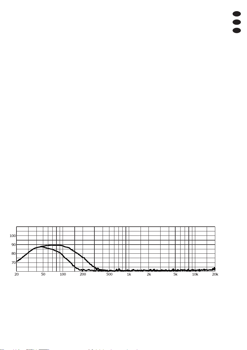
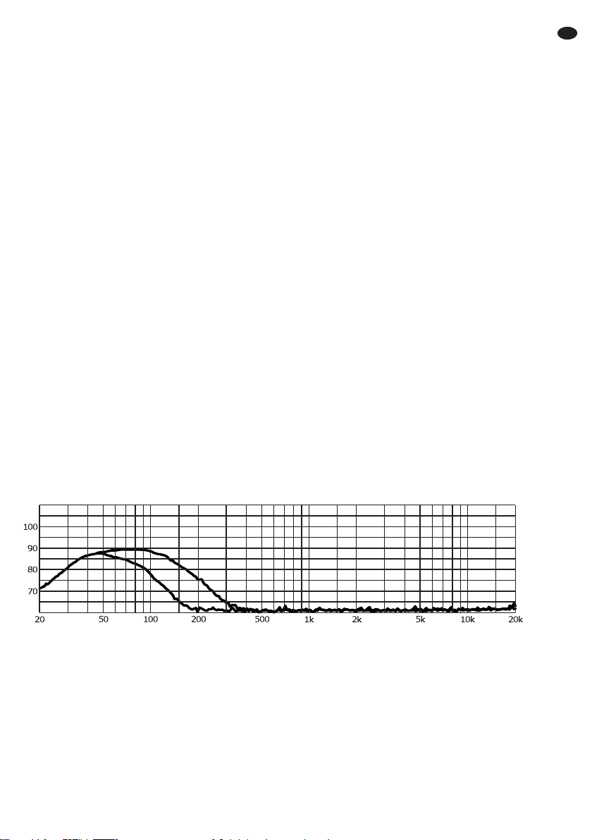
6 Technische Daten
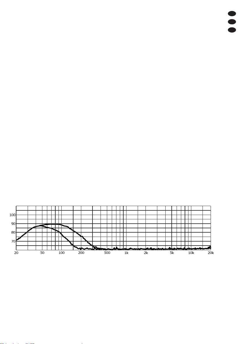
Frequenzbereich: . . . . . . . Diagramm unten
Verstärkerleistung: . . . . . . 120 WRMS,
200 WMAX
Lautsprecher-
Kennschalldruck: . . . . . . . 88 dB (1W/1m)
Max. Schalldruck: . . . . . . 108 dB
Eingänge (Empfindlichkeit, Impedanz, Anschluss)
LINE IN: . . . . . . . . . . . . 150 mV, 24 kΩ, Cinch
LFE: . . . . . . . . . . . . . . . 55 mV, 16 kΩ, Cinch
HIGH LEVEL IN: . . . . . 2,3 V, 440 Ω,
Schraubklemme mit
4-mm-Bananenbuchse
Stromversorgung: . . . . . . 230 V~/50 Hz
Leistungsaufnahme: . . . . max. 240 VA
Einsatztemperatur: . . . . . 0 – 40 °C
Abmessungen (B×H×T): 330 × 360 × 360 mm
Gewicht: . . . . . . . . . . . . . . 13 kg
Änderungen vorbehalten.
7
D
A
CH
Diese Bedienungsanleitung ist urheberrechtlich für MONACOR ®INTERNATIONAL GmbH & Co. KG
geschützt. Eine Reproduktion für eigene kommerzielle Zwecke – auch auszugsweise – ist untersagt.
[Hz]
[dB]
Frequenzgang bei Verwendung der Eingänge LINE IN oder HIGH LEVEL IN mit minimal und maximal eingestellter
Tiefpassfrequenz
All operating elements and connections de-
scribed can be found on the fold-out page 3.
1 Operating Elements
and Connections
1POWER LED
green subwoofer in operation
red subwoofer in standby mode or pro-
tective circuit activated
2VOLUME control
3CROSSOVER control to adjust the cutoff fre-
quency (50 – 150 Hz) of the low pass filter for the
inputs LINE IN and HIGH LEVEL IN
4POWER switch
5Support for the mains fuse;
always replace a blown fuse by one of the same
type only
6Cable for connection to a mains socket (230 V~/
50 Hz)
7Stereo signal input LINE IN as RCA jacks
8Mono signal input LFE as RCA jack
9PHASE reversal switch
10 STAND BY selector switch
position “OFF”: always in standby mode
position “ON”: always in operation
position “AUTO”:switching between the modes
operation and standby depending on the signal
level
11 Stereo signal input HIGH LEVEL IN for connec-
tion to the speaker output of an amplifier
There are banana jacks under the protective
caps of the screw terminals.
12 Feed-through outputs HIGH LEVEL OUT, con-
nected to the corresponding jacks HIGH LEVEL
IN (11), for connecting the other speakers
There are banana jacks under the protective
caps of the screw terminals.
2 Safety Notes
This unit corresponds to all relevant directives of
the EU and is therefore marked with .
Please observe the following items in any case:
The unit is suitable for indoor use only. Protect it
against dripping water and splash water, high air
humidity and heat (admissible ambient tempera-
ture range 0 – 40 °C).
Do not place any vessel filled with liquid on the
unit, e. g. a drinking glass.
The heat generated inside the unit must be dissi-
pated by air circulation. Do not cover the air vents
(bass-reflex openings).
Do not operate the unit and immediately discon-
nect the mains plug from the socket
1. if the unit or the mains cable is visibly dam-
aged,
2. if a defect might have occurred after the unit
was dropped or suffered a similar accident,
3. if malfunctions occur.
In any case the unit must be repaired by skilled
personnel.
A damaged mains cable must be replaced by
skilled personnel only.
Never pull the mains cable to disconnect the
mains plug from the socket, always seize the plug.
For cleaning only use a dry, soft cloth; never use
water or chemicals.
No guarantee claims for the unit and no liability
for any resulting personal damage or material
damage will be accepted if the unit is used for
other purposes than originally intended, if it is not
correctly connected or operated, or if it is not
repaired in an expert way.
If the unit is to be put out of operation
definitively, take it to a local recycling plant
for a disposal which will not be harmful to
the environment.
WARNING The unit uses dangerous mains volt-
age. Leave servicing to skilled per-
sonnel only. Inexpert handling or
modification of the unit may result in
electric shock.
8
GB

3 Applications
This compact active subwoofer is suited as a low-
frequency complement of existing audio systems
for hi-fi applications, home cinema and home
recording applications. It is equipped with a 25 cm
(10″) bass speaker. Its amplifier offers a peak out-
put power of 200 W.
The subwoofer features an adjustable low pass
filter, a volume control, a phase reversal switch and
an automatic standby mode. The integrated ampli-
fier is provided with protective circuits to prevent
overload and overheating.
Inputs are provided for connection to stereo out-
puts with line level and for connection to speaker
outputs (with feed-through facility for the other
speakers).
The subwoofer also features an LFE input. In
multi-channel systems for cinema applications,
e. g. “5.1”, the LFE channel (“Low Frequency
Effect” or “Low Frequency Enhancement”) is used
for low-frequency special effects.
4 Setting Up and Connecting
Set up the subwoofer on an even surface. It is not
important to place the subwoofer exactly in the mid-
dle between the stereo speakers as it will not be
possible to precisely locate the very low frequen-
cies reproduced by the subwoofer. However, do not
place it too close to walls or in corners; this would
distort the frequency response and prevent the
heat dissipation of the integrated amplifier. Like-
wise, do not cover the bass-reflex openings on the
lower side.
Prior to making connections or changing any exist-
ing connections, switch off the subwoofer and the
units to be connected.
Connect a signal source via one of the three
connection possibilities described in chapters 4.1
to 4.3.
4.1 Stereo input LINE IN
If a stereo output with line level is provided (e. g.
output of a preamplifier or mixer), connect this out-
put to the input LINE IN (7) on the subwoofer. From
the two stereo channels, a mono signal will be
created internally for the subwoofer.
If the outputs of the preamplifier or mixer are
already reserved for your audio system, use an
adapter to divide the output signal (e. g. ACA-120
from MONACOR).
4.2 Stereo input HIGH LEVEL IN
If no output with line level is available, connect the
inputs HIGH LEVEL IN (11) to the speaker outputs
of the amplifier (LEFT = left channel, RIGHT = right
channel). Observe the correct polarity of the con-
nections. When connecting, always switch off the
amplifier. Make sure that the cable ends used for
connection to the screw terminals are only stripped
as far as necessary and that no bare wires stick out
(danger of contact and short circuit). The feed-
through outputs HIGH LEVEL OUT (12) are directly
connected to the corresponding jacks HIGH
LEVEL IN. Use these jacks to connect the other
speaker systems.
There are banana jacks under the protective
caps of the screw terminals.
4.3 Mono input LFE
Connect the LFE output of a multi-channel system
or another mono output with line level to the jack
LFE (8).
Note: The adjustable low pass filter will not affect
the signal of a signal source connected to this input
as an LFE signal usually contains low-frequency
signals only.
4.4 Power supply
Connect the plug of the mains cable (6) to a mains
socket (230 V~/50 Hz).
WARNING If an amplifier is connected to the
inputs HIGH LEVEL IN (11), cover all
banana jacks not used with the pro-
tective caps; touching the connec-
tions may result in electric shock.
9
GB

5 Operation
Note: To prevent switching noise, always switch on
the units connected before switching on the
subwoofer and switch it off first after use.
1) Set the VOLUME control (2) to MIN (left stop) for
the time being and switch on the subwoofer with
the POWER switch (4). The POWER LED (1)
will light up.
2) With the STAND BY switch (10), switch on or off
the automatic standby mode.
Position “AUTO”:
The automatic standby mode is activated. The
subwoofer will automatically be in operation
once an input signal has been applied and the
VOLUME control (2) has been turned up accord-
ingly. The POWER LED (1) will show green. If
the signal level falls below a certain value for a
few minutes, the subwoofer will return to the
standby mode; the POWER LED will show red.
Position “ON”:
The automatic standby mode is deactivated.
After switching on, the subwoofer will always be
in operation. The POWER LED (1) will show
green.
Position “OFF”:
The subwoofer is always in standby mode. The
POWER LED (1) will show red. Thus, it will be
possible to set the subwoofer to the standby
mode immediately, e. g. for testing the switch-on
threshold in the position “AUTO” subsequently.
3) Reproduce sound, e. g. music, via the existing
audio system and add the desired low bass part
with the VOLUME control (2). Only turn up the
control to such an extent that the sound repro-
duced will not be distorted.
4) If the signal source is connected via the inputs
LINE IN (7) or HIGH LEVEL IN (11), adjust the
cutoff frequency of the low pass filter with the
CROSSOVER control (3) so that the subwoofer
will optimally complement the frequency re-
sponse of the other speakers. This filter will not
affect the input LFE (8).
If required, readjust the volume balance with
the VOLUME control (2).
5) Different distances of speakers to the listener
may result in phase interference (certain fre-
quencies will have a lower volume). To compen-
sate this, the phase of the subwoofer signal is
reversible with the PHASE reversal switch (9).
Test both switch positions to find the position
offering the bass reproduction of the highest vol-
ume at the listening position. Then readjust the
volume balance with the VOLUME control (2), if
required.
6) If the automatic standby mode is deactivated
( step 2), switch off the subwoofer with the
POWER switch (4) after use.
To prevent unnecessary power consumption,
it is always recommended to switch off the sub-
woofer when not in use for longer periods.
5.1 Protective circuits
The amplifier of the subwoofer is provided with pro-
tective circuits to prevent overload and overheat-
ing. If the POWER LED shows red although the
STAND BY switch (10) is set to “ON” or if the colour
of the POWER LED changes to red despite a suffi-
cient signal, a protective circuit has been activated.
In this case, switch off the subwoofer and eliminate
the cause of defect.
CAUTION Never adjust the audio system to a
very high volume. Permanent high
volumes may damage your hearing!
Your ear will get accustomed to high
volumes which do not seem to be that
high after some time. Therefore, do
not further increase a high volume
after getting used to it.
10
GB
6 Specifications
Frequency range: . . . . . . diagram below
Amplifier power: . . . . . . . 120 WRMS,
200 WMAX
Nominal SPL of speaker: . 88 dB (1 W / 1 m)
Max. SPL: . . . . . . . . . . . . 108 dB
Inputs (sensitivity, impedance, connection)
LINE IN: . . . . . . . . . . . . 150 mV, 24 kΩ, RCA
LFE: . . . . . . . . . . . . . . . 55 mV, 16 kΩ, RCA
HIGH LEVEL IN: . . . . . 2.3 V, 440 Ω,
screw terminal with
4 mm banana jack
Power supply: . . . . . . . . . 230 V~/50 Hz
Power consumption: . . . . 240 VA max.
Ambient temperature: . . . 0 – 40 °C
Dimensions (W × H × D): . 330 × 360 × 360 mm
Weight: . . . . . . . . . . . . . . 13 kg
Subject to technical modification.
11
GB
All rights reserved by MONACOR ®INTERNATIONAL GmbH & Co. KG. No part of this instruction manual
may be reproduced in any form or by any means for any commercial use.
[Hz]
[dB]
Frequency response when using the inputs LINE IN or HIGH LEVEL IN with the low pass frequency set to mini-
mum and maximum
Vous trouverez sur la page 3, dépliable, les élé-
ments et branchements décrits.
1 Eléments et branchements
1Témoin de fonctionnement
vert en fonctionnement
rouge stand by (mode veille)
ou si le circuit de protection est activé
2Potentiomètre de réglage de volume VOLUME
3Réglage CROSSOVER pour régler la fré-
quence de coupure (50 – 150 Hz) du filtre
passe-bas pour les entrées LINE IN et HIGH
LEVEL IN
4Interrupteur secteur POWER
5Porte-fusible : tout fusible fondu doit être rem-
placé impérativement par un fusible de même
type.
6Cordon à relier à une prise secteur 230 V~/
50 Hz
7Entrée signal stéréo LINE IN, prises RCA
8Entrée signal mono LFE, prise RCA
9Inverseur de phase PHASE
10 Commutateur STAND BY pour le mode de fonc-
tionnement veille
position “OFF”: toujours en mode veille
position “ON”: toujours en fonctionnement
position “AUTO”: commutation entre mode de
fonctionnement et veille selon le niveau du
signal
11 Entrée signal stéréo HIGH LEVEL pour bran-
cher à la sortie haut-parleur dʼun amplificateur
Les prises bananes se trouvent sous les caches
de protection des bornes à vis.
12 Sorties pour repiquage HIGH LEVEL OUT,
reliées aux prises HIGH LEVEL IN (11) corres-
pondantes, pour brancher les autres enceintes
Les prises bananes se trouvent sous les caches
de protection des bornes à vis.
2 Conseils dʼutilisation et de sécurité
Lʼappareil répond à toutes les directives néces-
saires de lʼUnion européenne et porte donc le sym-
bole .
Respectez scrupuleusement les points suivants :
Lʼappareil nʼest conçu que pour une utilisation en
intérieur. Protégez-le de tout type de projections
dʼeau, des éclaboussures, dʼune humidité élevée
de lʼair et de la chaleur (plage de température de
fonctionnement autorisée : 0 – 40 °C).
En aucun cas, vous ne devez poser dʼobjet
contenant du liquide ou un verre sur lʼappareil.
La chaleur dégagée par lʼappareil doit être éva-
cuée par une circulation dʼair correcte. En aucun
cas, les ouïes de ventilation (ouvertures bass-
reflex) ne doivent être obturée.
Ne faites pas fonctionner lʼappareil ou débran-
chez immédiatement la fiche du cordon du sec-
teur lorsque :
1. des dommages visibles apparaissent sur lʼap-
pareil ou sur le cordon secteur,
2. après une chute ou un cas similaire, vous avez
un doute sur lʼétat de lʼappareil,
3. des dysfonctionnements apparaissent.
Faites toujours appel à un technicien spécialisé
pour effectuer les réparations.
Tout cordon secteur endommagé ne doit être
remplacé que par un technicien habilité.
Ne débranchez jamais lʼappareil en tirant sur le
cordon secteur, tenez-le toujours par la fiche.
Pour nettoyer lʼappareil, utilisez uniquement un
chiffon sec et doux, en aucun cas, de produits
chimiques ou dʼeau.
Nous déclinons toute responsabilité en cas de
dommages corporels ou matériels résultants si
lʼappareil est utilisé dans un but autre que celui
pour lequel il a été conçu, sʼil nʼest pas correcte-
ment branché, utilisé ou nʼest pas réparé par une
personne habilitée, de même, la garantie devien-
drait caduque.
Lorsque lʼappareil est définitivement retiré
du service, vous devez le déposer dans
une usine de recyclage adaptée pour
contribuer à son élimination non polluante.
AVERTISSEMENT Lʼappareil est alimenté par une
tension secteur dangereuse. Ne
faites jamais de modification sur
lʼappareil. Une mauvaise mani-
pulation pourrait générer une
décharge électrique.
12
F
B
CH
3 Possibilités dʼutilisation
Ce subwoofer actif compact sert comme complé-
ment basse fréquence dʼinstallations audio exis-
tantes pour applications Hi-Fi, home cinéma et
home recording. Il est équipé dʼun haut-parleur de
grave 25 cm (10″) et dʼun amplificateur avec une
puissance de sortie crête de 200 W.
Il dispose dʼun filtre passe-bas réglable, dʼun
réglage de volume, dʼune inversion de phase com-
mutable et dʼun mode stand by automatique. Lʼam-
plificateur intégré est équipé de circuits de protec-
tion contre les surcharges et surchauffes.
Des entrées pour brancher aux sorties stéréo
avec niveau ligne et pour le branchement à des
sorties haut-parleurs (avec possibilité repiquage
pour les autres haut-parleurs) sont prévues.
En plus, le subwoofer dispose dʼune entrée LFE.
Dans des systèmes multicanaux pour applications
cinéma, par exemple “5.1”, le canal LFE (“Low Fre-
quency Effect” ou “Low Frequency Enhancement”)
permet de transmettre des effets spéciaux basse
fréquence.
4 Positionnement et branchements
Positionnez le subwoofer sur un support plat. Le
positionnement précis au centre entre les
enceintes stéréo nʼest pas capital puisque les fré-
quences très graves quʼil restitue ne peuvent pas
être localisées avec précision. Cependant, ne le
positionnez pas trop près des murs ou dans des
coins car cela fausse la réponse en fréquence et
peut gêner la dissipation de chaleur de lʼamplifica-
teur intégré. De même les ouvertures bass-reflex
situées dans la partie inférieure ne doivent pas être
obturées.
Avant dʼeffectuer les branchements ou de modifier
les branchements existants, veillez à éteindre le
subwoofer et les appareils reliés.
Reliez une source de signal via une des trois
possibilités de branchement décrites dans les cha-
pitres 4.1 à 4.3, au subwoofer.
4.1 Entrée stéréo LINE IN
Si une sortie stéréo avec niveau ligne existe (par
exemple sortie dʼun préamplificateur ou dʼune table
de mixage), reliez-la à lʼentrée LINE IN (7) du sub-
woofer. A partir des deux canaux stéréo, un signal
mono est constitué en interne pour le subwoofer.
Si les sorties du préamplificateur ou de la table
de mixage sont déjà configurées pour le branche-
ment de lʼinstallation audio existante, on peut utili-
ser un adaptateur pour diviser le signal de sortie
(par exemple ACA-120 de MONACOR).
4.2 Entrée stéréo HIGH LIVEL IN
Si aucune sortie avec niveau ligne nʼest disponible,
reliez les entrées HIGH LEVEL IN (11) aux sorties
haut-parleurs de lʼamplificateur (LEFT = canal
gauche, RIGHT = canal droit). Veillez à respecter la
polarité des branchements. Lorsque vous effectuez
les branchements, éteignez impérativement lʼam-
plificateur et assurez-vous que les extrémités de
câble pour le branchement aux bornes à vis ne
sont pas trop dénudées et quʼaucun fil nu ne sort
(risque de contact et de court-circuit). Les sorties
pour repiquage HIGH LEVEL OUT (12) sont direc-
tement reliées aux prises correspondantes HIGH
LEVEL IN. On peut relier ici les autres enceintes.
Les prises bananes se trouvent sous les caches
de protection des bornes à vis.
4.3 Entrée mono LFE
Reliez la sortie LFE dʼun système multicanal ou
une autre sortie mono avec niveau ligne à la prise
LFE (8).
Remarque: Le signal dʼune source de signal reliée
à cette entrée nʼest pas influencé par le filtre passe-
bas réglable puisquʼun signal LFE contient, en
général uniquement des signaux basse fréquence.
4.4 Alimentation
Reliez la fiche du cordon secteur (6) à une prise
secteur 230 V~/50 Hz.
AVERTISSEMENT Si un amplificateur est relié aux
bornes HIGH LEVEL IN (11), il
faut protéger toutes les prises
bananes non utilisées avec les
caches. Sinon, il y a risque de
décharge électrique en cas de
contacts des branchements.
13
F
B
CH

5 Utilisation
Conseil : Pour éviter tout bruit fort de commuta-
tion, allumez toujours les appareils reliés
avant dʼallumer le subwoofer et étei-
gnez-le en premier après utilisation.
1) Mettez le réglage VOLUME (2) tout dʼabord sur
MIN (butée de gauche) et allumez le subwoofer
avec lʼinterrupteur POWER (4). La LED (1) brille.
2) Avec lʼinterrupteur STAND BY (10), activez ou
désactivez le mode stand by automatique.
Position “AUTO” : le mode stand by automatique
est activé. Le subwoofer se met automatique-
ment en fonction lorsquʼun signal dʼentrée est
présent et que le réglage VOLUME (2) est
tourné en conséquence. Le témoin de fonction-
nement (1) brille en vert. Si le niveau de signal
diminue pendant quelques minutes sous un cer-
tain seuil, le subwoofer revient au mode stand
by ; le témoin de fonctionnement brille en rouge.
Position “ON” : le mode stand by automatique
est désactivé, le subwoofer est toujours en fonc-
tionnement une fois allumé, le témoin de fonc-
tionnement (1) brille en vert.
Position “OFF” : le subwoofer est toujours en
mode stand by, le témoin de fonctionnement (1)
brille en rouge. Ainsi, on peut mettre le subwoo-
fer en mode stand by immédiatement pour, par
exemple, tester ensuite en position “AUTO” le
seuil de commutation.
3) Via lʼinstallation audio existante, restituez par
exemple la musique et avec le réglage VOLUME
(2), mixez la part de graves souhaitée. Tournez
le réglage jusquʼà ce que le son soit restitué de
manière non distordue.
4) Si la source de signal est reliée via les entrées
LINE IN (7) ou HIGH LEVEL IN (11), réglez la
fréquence de coupure du filtre passe-bas avec
le réglage CROSSOVER (3) de telle sorte que le
subwoofer complète de manière optimale la
réponse en fréquence des autres haut-parleurs.
Ce filtre nʼa pas dʼeffet à lʼentrée LFE (8).
Si besoin, corrigez la balance de volume
avec le réglage VOLUME (2).
5) Des distances différentes des haut-parleurs
avec lʼauditoire peuvent créer des interférences
de phase (certaines fréquences sont moins
fortes). Pour compenser, on peut avec lʼinterrup-
teur PHASE (9), inverser la phase du signal du
subwoofer.
Testez les deux positions de lʼinterrupteur
pour trouver celle proposant la reproduction des
graves avec le volume le plus élevé au niveau
de la position dʼécoute. Si besoin, corrigez en
conséquence la balance de volume avec le
réglage VOLUME (2).
6) Si le mode stand by automatique est désactivé
(point 2), éteignez le subwoofer avec lʼinter-
rupteur POWER (4) après utilisation.
Dans tous les cas, il est recommandé dʼétein-
dre le subwoofer en cas de non utilisation pro-
longée pour éviter toute consommation inutile.
5.1 Circuits de protection
Lʼamplificateur du subwoofer est doté de circuits de
protection contre les surcharges et surchauffes. Si
le témoin de fonctionnement brille en rouge, bien
que lʼinterrupteur STAND BY (10) soit sur “ON”, ou
si la couleur du témoin de fonctionnement change
et passe au rouge pendant le fonctionnement mal-
gré un signal suffisant, un circuit de protection est
activé. Dans ce cas, il faut éteindre le subwoofer et
résoudre le problème.
ATTENTION Ne réglez jamais le volume de lʼins-
tallation audio trop fort. Un volume
trop élevé peut, à long terme, générer
des troubles de lʼaudition ! Lʼoreille
sʼhabitue à des volumes élevés et ne
les perçoit plus comme tels au bout
dʼun certain temps. Nous vous
conseillons donc de régler le volume
et de ne plus le modifier.
14
F
B
CH
6 Caractéristiques techniques
Bande passante : . . . . . . . diagramme
ci-dessous
Puissance amplificateur : . 120 WRMS,
200 WMAX
Pression sonore nominale
haut-parleurs : . . . . . . . . . 88 dB (1 W / 1 m)
Pression sonore
maximale : . . . . . . . . . . . . 108 dB
Entrées (sensibilité, impédance, branchement)
LINE IN : . . . . . . . . . . . 150 mV, 24 kΩ, RCA
LFE : . . . . . . . . . . . . . . 55 mV, 16 kΩ, RCA
HIGH LEVEL IN : . . . . . 2,3 V, 440 Ω, borne à
vis avec prise banane
4mm
Alimentation : . . . . . . . . . . 230 V~/50 Hz
Consommation : . . . . . . . max. 240 VA
Température fonc. : . . . . . 0 – 40 °C
Dimensions (L×H×P): .. 330 × 360 × 360 mm
Poid : . . . . . . . . . . . . . . . . 13 kg
Tout droit de modification réservé.
15
F
B
CH
Notice dʼutilisation protégée par le copyright de MONACOR ®INTERNATIONAL GmbH & Co. KG. Toute
reproduction même partielle à des fins commerciales est interdite.
[Hz]
[dB]
Réponse en fréquence si on utilise les entrées LINE IN ou HIGH LEVEL avec une fréquence passe-bas réglée au
minimum et maximum
A pagina 3, se aperta completamente, vedrete
sempre gli elementi di comando e i collega-
menti descritti.
1 Elementi di comando
e collegamenti
1Spia di funzionamento
verde in funzione
rosso stand-by
o con circuito attivo di protezione
2Regolatore VOLUME
3Regolatore CROSSOVER per impostare la fre-
quenza di taglio (50 – 150 Hz) del filtro passa-
basso per gli ingressi LINE IN e HIGH LEVEL
IN
4Interruttore di rete POWER
5Portafusibili;
sostituire un fusibile difettoso solo con uno dello
stesso tipo
6Cavo per il collegamento con una presa di rete
(230 V~/50 Hz)
7Ingresso dei segnali stereo LINE IN come prese
RCA
8Ingresso dei segnali mono LFE come presa
RCA
9Commutatore dʼinversione di fase PHASE
10 Commutatore STAND BY per il modo stand-by
Posizione “OFF”: sempre in stand-by
Posizione “ON”: sempre in funzione
Posizione “AUTO”: commutazione fra funzione
e stand-by a seconda del livello dei segnali
11 Ingresso dei segnali stereo HIGH LEVEL IN per
il collegamento con lʼuscita per altoparlanti di un
amplificatore
Sotto i cappucci dei morsetti a vite si trovano
delle prese a banana.
12 Uscite passanti HIGH LEVEL OUT, collegate
con le relative prese HIGH LEVEL IN (11), per il
collegamento degli altri altoparlanti
Sotto i cappucci dei morsetti a vite si trovano
delle prese a banana.
2 Avvertenze di sicurezza
Lʼapparecchio è conforme a tutte le direttive rile-
vanti dellʼUE e pertanto porta la sigla .
Si devono osservare assolutamente anche i
seguenti punti:
Usare lʼapparecchio solo allʼinterno di locali e pro-
teggerlo dallʼacqua gocciolante e dagli spruzzi
dʼacqua, da alta umidità dellʼaria e dal calore
(temperatura dʼimpiego ammessa fra 0 e 40 °C).
Non depositare sullʼapparecchio dei contenitori
riempiti di liquidi, p. es. bicchieri.
Devʼessere garantita la libera circolazione del-
lʼaria per dissipare il calore che viene prodotto
allʼinterno dellʼapparecchio. Non coprire in nes-
sun modo le fessure dʼaerazione (per il bass-
reflex).
Non mettere in funzione lʼapparecchio e staccare
subito la spina rete se:
1. lʼapparecchio o il cavo rete presentano dei
danni visibili;
2. dopo una caduta o dopo eventi simili sussiste
il sospetto di un difetto;
3. lʼapparecchio non funziona correttamente.
Per la riparazione rivolgersi sempre ad unʼoffi-
cina competente.
Il cavo rete, se danneggiato, deve essere sosti-
tuito solo da un laboratorio specializzato.
Staccare il cavo rete afferrando la spina, senza
tirare il cavo.
Per la pulizia usare solo un panno morbido,
asciutto; non impiegare in nessun caso prodotti
chimici o acqua.
Nel caso dʼuso improprio, di collegamenti sba-
gliati, dʼimpiego scorretto o di riparazione non a
regola dʼarte dellʼapparecchio, non si assume
nessuna responsabilità per eventuali danni con-
sequenziali a persone o a cose e non si assume
nessuna garanzia per lʼapparecchio.
Se si desidera eliminare lʼapparecchio
definitivamente, consegnarlo per lo smalti-
mento ad unʼistituzione locale per il rici-
claggio.
AVVERTIMENTO Lʼapparecchio funziona con peri-
colosa tensione di rete. Non inter-
venire mai personalmente al suo
interno! La manipolazione scor-
retta può provocare una scarica
elettrica pericolosa.
16
I

3 Possibilità dʼimpiego
Questo subwoofer attivo compatto serve come
integrazione per frequenze basse in impianti di
altoparlanti nei settore hifi, home-cinema e home-
recording. È equipaggiato con un woofer di 25 cm
(10″), e il suo amplificatore ha una potenza di picco
di 200 W.
Il subwoofer possiede un filtro passa-basso
regolabile, un regolatore del volume, una commu-
tazione dʼinversione di fase attivabile e stand-by
automatico. Lʼamplificatore integrato è equipag-
giato con circuiti di protezione contro sovraccarico
e surriscaldamento.
Esistono degli ingressi per il collegamento con
uscite stereo con livello Line nonché per il collega-
mento con uscite per altoparlanti (con possibilità di
passaggio agli altri altoparlanti).
In più, il subwoofer dispone di un ingresso LFE.
Nei sistemi multicanali nel settore dei cinema,
p. es. “5.1”, il canale LFE serve per la trasmissione
degli effetti speciali a bassa frequenza (“Low Fre-
quency Effect” o “Low Frequency Enhancement”).
4 Collocamento e collegamento
Collocare il subwoofer su un fondo piano. Lʼesatta
posizione nel centro fra gli altoparlanti stereo non è
decisiva con il subwoofer dato che non è possibile
localizzare con esattezza le basse frequenze che
riproduce. Ma non posizionarlo troppo vicino a
pareti o in angoli perché questo fatto falsifiche-
rebbe la risposta in frequenza e ostacolerebbe la
dissipazione del calore prodotto dallʼamplificatore.
Anche le aperture bass-reflex poste sul lato infe-
riore con devono essere coperte.
Prima di collegare il subwoofer o di modificare i col-
legamenti esistenti, spegnere il subwoofer e gli
apparecchi da collegare.
Collegare una fonte di segnali con il subwoofer
utilizzando una delle tre possibilità di collegamento
descritte nei capitoli 4.1 a 4.3.
4.1 Ingresso stereo LINE IN
Se è presente unʼuscita stereo con livello Line
(p. es. uscita di un preamplificatore o mixer), colle-
garla con lʼingresso LINE IN (7) del subwoofer. Dai
due canali stereo si genera internamente un
segnale mono per il subwoofer.
Se le uscite del preamplificatore o mixer sono
già occupate dal collegamento dellʼimpianto esi-
stente di altoparlanti, si può usare un adattatore per
raddoppiare le uscite del segnale audio (p. es.
ACA-120 di MONACOR).
4.2 Ingresso stereo HIGH LEVEL IN
Se non è disponibile nessunʼuscita con livello Line,
collegare i contatti HIGH LEVEL IN (11) con le
uscite per altoparlanti dellʼamplificatore (LEFT =
canale sinistro, RIGHT = canale destro). Rispettare
la polarità dei contatti. Prima del collegamento spe-
gnere assolutamente lʼamplificatore e fare atten-
zione che i terminali dei cavi ai morsetti a vite non
siano deisolati troppo con sporgenza di fili spelati
(pericolo di contatto e di cortocircuito). Le uscite
passanti HIGH LEVEL OUT (12) sono collegate
direttamente con le relative prese HIGH LEVEL IN.
Qui si possono collegare le altre casse acustiche.
Sotto i cappucci dei morsetti a vite si trovano
delle prese a banana.
4.3 Ingresso mono LFE
Collegare lʼuscita LFE di un sistema multicanale o
unʻaltra uscita mono con livello Line con la presa
LFE (8).
Nota: Il segnale della fonte collegata qui non è
influenzato dal filtro passa-basso regolabile, dato
che un segnale LFE contiene di regola solo segnali
a bassa frequenza.
4.4 Alimentazione
Inserire la spina del cavo (6) in una presa di rete
(230 V~/50 Hz).
AVVERTIMENTO Se è collegato un amplificatore
con i contatti HIGH LEVEL IN
(11), tutte le prese banana non
occupate devono essere coperte
con i cappucci. Altrimenti, toc-
cando i contatti, esiste il pericolo
di una scarica elettrica.
17
I

5 Funzionamento
Nota: Per escludere rumori di commutazione,
accendere il subwoofer sempre dopo gli
apparecchi collegati, e dopo lʼuso spegnerlo
per primo.
1) Portare il regolatore VOLUME (2) per il
momento su MIN (arresto a sinistra) e accen-
dere il subwoofer con lʼinterruttore POWER (4).
Si accende il LED (1).
2) Con il commutatore STAND BY (10) attivare o
disattivare lo stand-by automatico.
Posizione “AUTO”:
Lo standby automatico è attivo. Il subwoofer si
mette automaticamente in funzione se è pre-
sente un segnale allʼingresso e se il regolatore
VOLUME (2) è aperto sufficientemente. Allora,
la spia di funzionamento (1) è accesa di colore
verde. Se il livello del segnale cade per alcuni
minuti sotto un determinato valore, il subwoofer
ritorna nel modo di stand-by: la spia di funziona-
mento prende il colore rosso.
Posizione “ON”:
Lo standby automatico è disattivato. Dopo lʼac-
censione, il subwoofer è sempre in funzione. La
spia di funzionamento (1) è verde.
Posizione “OFF”:
Il subwoofer è sempre in stand-by. La spia di
funzionamento (1) è rossa. In questo modo si
può attivare immediatamente lo stand-by, p. es.
per testare la soglia dʼinserimento nella posi-
zione “AUTO”.
3) Riprodurre p. es. della musica per mezzo del-
lʼimpianto esistente di altoparlanti e aggiungere
la parte di frequenze basse per mezzo del rego-
latore VOLUME (2). Aprire il regolatore solo al
punto da non aver delle distorsioni del suono.
4) Se la fonte di segnali è collegata per mezzo degli
ingressi LINE IN (7) o HIGH LEVEL IN (11), con
il regolatore CROSSOVER (3) impostare la fre-
quenza di taglio del passa-basso in modo che il
subwoofer completi in modo ottimale la risposta
in frequenza degli altri altoparlanti. Questo filtro
non influenza lʼingresso LFE (8).
Se necessario, correggere il bilanciamento
del volume con il regolatore VOLUME (2).
5) In caso di distanze differenti degli altoparlanti
dallʼascoltatore, si possono manifestare delle
cancellazioni di fasi (determinate frequenze
diventano più deboli). Per compensare questo
effetto, con il commutatore PHASE (9) è possi-
bile invertire la fase del segnale del subwoofer.
Con delle prove pratiche si può comprendere
con quale posizione del commutatore si ottiene
la migliore riproduzione dei bassi al posto del-
lʼascoltatore. Se necessario, correggere succes-
sivamente il bilanciamento del volume con il
regolatore VOLUME (2).
6) Se lo stand-by automatico è disattivato
(punto 2), dopo lʼuso spegnere il subwoofer
con lʼinterruttore POWER (4).
In ogni caso è consigliabile spegnere il sub-
woofer quando non è usato per un certo periodo
per evitare consumi inutili di energia elettrica.
5.1 Circuiti di protezione
Lʼamplificatore del subwoofer è equipaggiato con
circuiti di protezione contro sovraccarico e surri-
scaldamento. Se la spia di funzionamento si
accende di rosso nonostante il commutatore
STAND BY (10) si trovi in posizione “ON”, oppure
se durante il funzionamento il colore della spia di
funzionamento diventa rosso alla presenza di un
segnale sufficientemente potente, significa che un
circuito di protezione è attivo. In questo caso
occorre spegnere il subwoofer e eliminare il gua-
sto.
AVVERTIMENTO
Mai tenere molto alto il volume del-
lʼimpianto audio. A lungo andare, il
volume eccessivo può procurare
danni allʼudito! Lʼorecchio si abitua
agli alti volumi e dopo un certo
tempo non se ne rende più conto.
Perciò non aumentare il volume
successivamente.
18
I

6 Dati tecnici
Banda passante : . . . . . . . vedere il
diagramma in fondo
Potenza dellʼamplificatore: 120 WRMS,
200 WMAX
Pressione sonora nominale
dellʼaltoparlante: . . . . . . . 88 dB (1W/1m)
Pressione sonora max.: . . 108 dB
Ingressi (sensibilità, impedenza, contatto)
LINE IN: . . . . . . . . . . . . 150 mV, 24 kΩ, RCA
LFE: . . . . . . . . . . . . . . . 55 mV, 16 kΩ, RCA
HIGH LEVEL IN: . . . . . 2,3 V, 440 Ω,
morsetto a vite con
presa a banana 4 mm
Alimentazione: . . . . . . . . . 230 V~/50 Hz
Potenza assorbita: . . . . . . max. 240 VA
Temperatura dʼesercizio: . 0 – 40 °C
Dimensioni (l×h×p): .... 330 × 360 × 360 mm
Peso: . . . . . . . . . . . . . . . . 13 kg
Con riserva di modifiche tecniche.
19
I
La MONACOR ®INTERNATIONAL GmbH & Co. KG si riserva ogni diritto di elaborazione in qualsiasi forma
delle presenti istruzioni per lʼuso. La riproduzione – anche parziale – per propri scopi commerciali è vietata.
[Hz]
[dB]
Risposta in frequenza con gli ingressi LINE IN o HIGH LEVEL IN con frequenza di taglio regolata sul minimo e sul
massimo
Puede encontrar todos los elementos de fun-
cionamiento y las conexiones que se describen
en la página 3 desplegable.
1 Elementos de Funcionamiento
y Conexiones
1LED POWER
Verde Subwoofer en funcionamiento
Rojo Subwoofer en modo Standby o cir-
cuito de protección activado
2Control de volumen VOLUME
3Control CROSSOVER para ajustar la frecuen-
cia de corte (50 – 150 Hz) del filtro pasa bajo
para las entradas LINE IN y HIGH LEVEL IN
4Interruptor POWER
5Soporte para el fusible de corriente;
Cambie siempre un fusible fundido sólo por otro
del mismo tipo.
6Cable de corriente para conectar a una toma
(230 V~/50 Hz)
7Entrada de señal estéreo LINE IN como tomas
RCA
8Entrada de señal mono LFE como toma RCA
9Interruptor de inversión de fase PHASE
10 Interruptor selector STAND BY para el modo
Standby
Posición “OFF”: Siempre en modo Standby
Posición “ON”: Siempre en funcionamiento
Posición “AUTO”: Cambio entre los modos de
funcionamiento y Standby dependiendo del
nivel de señal
11 Entrada de señal estéreo HIGH LEVEL IN para
conectar a la salida de altavoz de un amplifica-
dor
Hay tomas banana bajo las fundas de protec-
ción de los terminales de tornillo.
12 Salidas alimentadas HIGH LEVEL OUT, conec-
tadas a las tomas correspondientes HIGH
LEVEL IN (11), para conectar a los demás alta-
voces
Hay tomas banana bajo las fundas de protec-
ción de los terminales de tornillo.
2 Notas de Seguridad
Este aparato cumple con todas las directivas rele-
vantes por la UE y por lo tanto está marcado con el
símbolo .
Preste atención a los siguientes puntos bajo cual-
quier circunstancia:
El aparato está adecuado sólo para utilizarlo en
interiores. Proteja el aparato de goteos y salpica-
duras, elevada humedad del aire y calor (tempe-
ratura ambiente admisible: 0 – 40 ºC).
No coloque ningún recipiente con líquido encima
del aparato, p. ej. un vaso.
El calor generado dentro del aparato tiene que
disiparse con la circulación del aire. No cubra las
rejillas de ventilación (aperturas Bass Reflex).
No utilice el aparato y desconecte inmediata-
mente la toma de corriente del enchufe si:
1. El aparato o el cable de corriente están visi-
blemente dañados.
2. El aparato ha sufrido daños después de una
caída o accidente similar.
3. No funciona correctamente.
Sólo el personal cualificado puede reparar el
aparato bajo cualquier circunstancia.
Un cable de corriente dañado sólo puede repa-
rarse por el personal cualificado.
No tire nunca del cable de corriente para desco-
nectar el enchufe de la toma de corriente, tire
siempre del enchufe.
Utilice sólo un paño suave y seco para la lim-
pieza; no utilice nunca ni agua ni productos quí-
micos.
No podrá reclamarse garantía o responsabilidad
alguna por cualquier daño personal o material
producido si se utiliza el aparato para fines dife-
rentes a los originalmente concebidos, si no se
conecta o no se utiliza correctamente, o sino se
repara por expertos.
Si va a poner el aparato fuera de servicio
definitivamente, llévelo a la planta de reci-
claje de la zona para que su eliminación
no sea perjudicial para el medio ambiente.
ADVERTENCIA El aparato utiliza un voltaje peli-
groso. Deje el mantenimiento en
manos del personal cualificado. El
manejo inexperto o la modifica-
ción del aparato pueden provocar
una descarga.
20
E
This manual suits for next models
1
Table of contents
Languages:
Other IMG STAGE LINE Subwoofer manuals

IMG STAGE LINE
IMG STAGE LINE PSUB-215 User manual

IMG STAGE LINE
IMG STAGE LINE PSUB-418AK User manual

IMG STAGE LINE
IMG STAGE LINE PSUB-12 AKA User manual

IMG STAGE LINE
IMG STAGE LINE PSUB-418AK User manual

IMG STAGE LINE
IMG STAGE LINE MEGA-215DSP User manual

IMG STAGE LINE
IMG STAGE LINE CALDERA-B10 User manual

IMG STAGE LINE
IMG STAGE LINE PSUB-115AK User manual

IMG STAGE LINE
IMG STAGE LINE PSUB-12AKA User manual

IMG STAGE LINE
IMG STAGE LINE SOUND -100SUB User manual

IMG STAGE LINE
IMG STAGE LINE PSUB-15AKA User manual


