IMG STAGE LINE PSUB-12AKA User manual

BEDIENUNGSANLEITUNG • INSTRUCTION MANUAL
MODE D’EMPLOI • ISTRUZIONI PER L’USO • GEBRUIKSAANWIJZING
MANUAL DE INSTRUCCIONES • INSTRUKCJA OBSŁUGI
SIKKERHEDSOPLYSNINGER • SÄKERHETSFÖRESKRIFTER • TURVALLISUUDESTA
PSUB-12AKA Bestellnummer 25.4310
PSUB-15AKA Bestellnummer 25.4320
SUBWOOFERBOX MIT
STEREO-MISCHVERSTÄRKER
SUBWOOFER SYSTEM WITH STEREO MIXING AMPLIFIER
ENCEINTE SUBWOOFER AVEC AMPLIFICATEUR MIXEUR STÉRÉO
CASSA SUBWOOFER CON AMPLIFICATORE MIXER STEREO
All manuals and user guides at all-guides.com
all-guides.com
2
Bevor Sie einschalten …
Wir wünschen Ihnen viel Spaß mit Ihrem neuen
Gerät von „img Stage Line“. Bitte lesen Sie diese
Bedienungsanleitung vor dem Betrieb gründlich
durch. Nur so lernen Sie alle Funktionsmöglich-
keiten kennen, vermeiden Fehlbedienungen und
schützen sich und Ihr Gerät vor eventuellen Schä-
den durch unsachgemäßen Gebrauch. Heben
Sie die Anleitung für ein späteres Nachlesen auf.
Der deutsche Text beginnt auf der Seite 4.
Before switching on …
We wish you much pleasure with your new “img
Stage Line” unit. Please read these operating
instructions carefully prior to operating the unit.
Thus, you will get to know all functions of the unit,
operating errors will be prevented, and yourself
and the unit will be protected against any damage
caused by improper use. Please keep the operat-
ing instructions for later use.
The English text starts on page 8.
Avant toute installation …
Nous vous souhaitons beaucoup de plaisir à uti-
liser cet appareil “img Stage Line”. Lisez ce mode
dʼemploi entièrement avant toute utilisation. Uni-
quement ainsi, vous pourrez apprendre lʼensem-
ble des possibilités de fonctionnement de lʼappa-
reil, éviter toute manipulation erronée et vous
protéger, ainsi que lʼappareil, de dommages
éventuels engendrés par une utilisation inadap-
tée. Conservez la notice pour pouvoir vous y
reporter ultérieurement.
La version française se trouve page 12.
Prima di accendere …
Vi auguriamo buon divertimento con il vostro
nuovo apparecchio di “img Stage Line”. Leggete
attentamente le istruzioni prima di mettere in fun-
zione lʼapparecchio. Solo così potete conoscere
tutte le funzionalità, evitare comandi sbagliati e
proteggere voi stessi e lʼapparecchio da even-
tuali danni in seguito ad un uso improprio. Con-
servate le istruzioni per poterle consultare anche
in futuro.
Il testo italiano inizia a pagina 16.
D
A
CH
GB
Innan du slår på enheten …
Vi önskar dig mycket glädje med din nya “img
Stage Line” produkt. Läs igenom säkerhetsföre-
skrifterna innan enheten tas i bruk för att undvika
skador till följd av felaktig hantering. Behåll
instruktionerna för framtida bruk.
Säkerhetsföreskrifterna återfinns på sidan 32.
F
B
CH
I
SFIN
Antes de la utilización …
Le deseamos una buena utilización para su nue-
vo aparato “img Stage Line”. Por favor, lea estas
instrucciones de uso atentamente antes de hacer
funcionar el aparato. De esta manera conocerá
todas las funciones de la unidad, se prevendrán
errores de operación, usted y el aparato estarán
protegidos en contra de todo daño causado por
un uso inadecuado. Por favor, guarde las instruc-
ciones para una futura utilización.
El texto en español empieza en la página 24.
Voor u inschakelt …
Wij wensen u veel plezier met uw nieuwe appa-
raat van “img Stage Line”. Lees deze gebruikers-
handleiding grondig door, alvorens het apparaat
in gebruik te nemen. Alleen zo leert u alle functies
kennen, vermijdt u foutieve bediening en behoedt
u zichzelf en het apparaat voor eventuele schade
door ondeskundig gebruik. Bewaar de handlei-
ding voor latere raadpleging.
De Nederlandstalige tekst vindt u op pagina 20.
Przed uruchomieniem …
Zyczymy zadowolenia z nowego produktu “img
Stage Line”. Dzięki tej instrukcji obsługi będą
państwo w stanie poznać wszystkie funkcje tego
urządzenia. Stosując się do instrukcji unikną
państwo błędów i ewentualnego uszkodzenia
urządzenia na skutek nieprawidłowego użytko-
wania. Prosimy zachować instrukcję.
Tekst polski zaczyna się na stronie 28.
Før du tænder …
Tillykke med dit nye “img Stage Line” produkt.
Læs sikkerhedsanvisningerne nøje før ibrugtag-
ning, for at beskytte Dem og enheden mod ska-
der, der skyldes forkert brug. Gem manualen til
senere brug.
Sikkerhedsanvisningerne findes på side 32.
E
PL DK
NL
B
wwwwww..iimmggssttaaggeelliinnee..ccoomm
Ennen kytkemistä …
Toivomme Sinulle paljon miellyttäviä hetkiä uuden
“img Stage Line” laitteen kanssa. Ennen laitteen
käyttöä pyydämme Sinua huolellisesti tutustu-
maan turvallisuusohjeisiin. Näin vältyt vahingoilta,
joita virheellinen laitteen käyttö saattaa aiheuttaa.
Ole hyvä ja säilytä käyttöohjeet myöhempää tar-
vetta varten.
Turvallisuusohjeet löytyvät sivulta 33.
All manuals and user guides at all-guides.com

3
Signal
signal
signal
segnale
signaal
señal
sygnał
Masse
ground
masse
massa
massa
masa
mase
1 2 3
Masse Signal + Signal
-
ground signal + signal
-
masse signal + signal
-
massa segnale + segnale
-
massa signaal + signaal
-
masa señal + señal
-
mase sygnał + sygnał
-
All manuals and user guides at all-guides.com

D
A
CH
Auf der ausklappbaren Seite 3 finden Sie alle be-
schriebenen Bedienelemente und Anschlüsse.
1 Übersicht der Bedienelemente
und Anschlüsse
1Regler XOVER FREQ zum Einstellen der Trenn-
frequenz für den Subwoofer und die Stereo-Laut-
sprecherausgänge von 80 Hz bis 250 Hz
2Regler SUB LEVEL für die Subwoofer-Laut-
stärke
3Klangregler TREBLE für die Höhen
4Klangregler BASS für die Tiefen
5Regler BAL zum Einstellen der Balance für die
Stereo-Lautsprecherausgänge (17)
6LED CLIP SUB; zeigt die Übersteuerung des
Subwoofer-Verstärkers an
7LED CLIP L/R; zeigt die Übersteuerung des
Stereo-Verstärkers an
8Signal-LED
9Lautstärkeregler LINE LEVEL für den Eingang
LINE INPUT (10) oder (13)
10 Eingang LINE INPUT (XLR-Buchsen) zum sym-
metrischen Anschluss einer Stereo-Signalquelle
mit Line-Pegel
11 Signal-LED
12 Lautstärkeregler MIC LEVEL für den Eingang
MIC INPUT (15)
13 Eingang LINE INPUT (Cinch-Buchsen) zum
asymmetrischen Anschluss einer Stereo-Sig-
nalquelle mit Line-Pegel, alternativ zu den XLR-
Buchsen (10)
14 Ausgang PAR. LINE OUTPUT (Cinch-Buchsen)
zum Weiterleiten des Line-Eingangssignals
z. B. zu einer weiteren Lautsprecheranlage
15 Eingang MIC INPUT (6,3-mm-Klinkenbuchse,
asymmetrisch beschaltet) zum Anschluss eines
Mikrofons
16 Kühlrippen
17 Ausgänge für die Stereolautsprecher; OUTPUT
LEFT für den linken, OUTPUT RIGHT für den
rechten Lautsprecher
18 beleuchteter Netzschalter POWER
19 Halterung für die Netzsicherung
Eine durchgebrannte Sicherung nur durch eine
gleichen Typs ersetzen.
20 Netzbuchse zum Anschluss an eine Steckdose
(230 V~/50 Hz) über das beiliegende Netzkabel
2 Hinweise
für den sicheren Gebrauch
Das Gerät entspricht allen relevanten Richtlinien
der EU und ist deshalb mit gekennzeichnet.
Beachten Sie auch unbedingt folgende Punkte:
GVerwenden Sie das Gerät nur im Innenbereich
und schützen Sie es vor Tropf- und Spritzwasser,
hoher Luftfeuchtigkeit und Hitze (zulässiger Ein-
satztemperaturbereich 0 – 40 °C).
GStellen Sie keine mit Flüssigkeit gefüllten Ge-
fäße, z. B. Trinkgläser, auf das Gerät.
GDie beim Betrieb entstehende Wärme wird durch
Luftzirkulation an den Kühlrippen (16) abgege-
ben. Decken Sie diese deshalb nicht ab und hal-
ten Sie entsprechend Abstand z. B. zu einer
Wand.
GNehmen Sie das Gerät nicht in Betrieb oder zie-
hen Sie sofort den Netzstecker aus der Steck-
dose,
1. wenn sichtbare Schäden am Gerät oder am
Netzkabel vorhanden sind,
2. wenn nach einem Sturz oder Ähnlichem der
Verdacht auf einen Defekt besteht,
3. wenn Funktionsstörungen auftreten.
Geben Sie das Gerät in jedem Fall zur Reparatur
in eine Fachwerkstatt.
GZiehen Sie den Netzstecker nie am Kabel aus
der Steckdose, fassen Sie immer am Stecker an.
GVerwenden Sie für die Reinigung nur ein trocke-
nes, weiches Tuch, niemals Wasser oder Chemi-
kalien.
GWird das Gerät zweckentfremdet, nicht richtig
installiert, falsch bedient oder nicht fachgerecht
repariert, kann keine Haftung für daraus resultie-
rende Sach- oder Personenschäden und keine
Garantie für das Gerät übernommen werden.
WARNUNG Das Gerät wird mit lebensgefährlich
hoher Netzspannung versorgt. Neh-
men Sie deshalb niemals selbst Ein-
griffe am Gerät vor. Es besteht die
Gefahr eines elektrischen Schlages.
Soll das Gerät endgültig aus dem Betrieb
genommen werden, übergeben Sie es zur
umweltgerechten Entsorgung einem örtli-
chen Recyclingbetrieb.
4
All manuals and user guides at all-guides.com

D
A
CH
5
3 Einsatzmöglichkeiten
Die PSUB-12AKA und PSUB-15AKA sind leis-
tungsfähige Aktiv-Subwooferboxen in robusten
Holzgehäusen. Die Boxen besitzen einen einge-
bauten Stereo-Endverstärker, zwei mischbare Ein-
gangskanäle und Klangregler. Es sind daher zum
einfachen Aufbau einer kompakten Lautsprecher-
anlage zusätzlich nur zwei Lautsprecherboxen für
die Mittel-Hochtonwiedergabe erforderlich (z. B.
PAB-306 oder PAB-308 von „img Stage Line“).
Die Subwooferboxen verfügen über eine Fre-
quenzweiche mit einer einstellbaren Trennfre-
quenz (80 – 250 Hz), die das Signal auf den
Subwoofer und die angeschlossenen Stereolaut-
sprecher aufteilt.
Die Verstärker sind mit einem Limiter gegen
Überlastung und mit Schutzschaltungen gegen
Kurzschluss und Überhitzung ausgestattet.
Die Stativhülse auf der Oberseite des Subwoo-
fers bietet eine Montagemöglichkeit für eine Laut-
sprecherbox.
4 Aufstellen
Die Subwooferbox auf einen festen Untergrund
stellen. Bei der Verwendung eines einzelnen Sub-
woofers ist die genaue Positionierung in der Mitte
zwischen den Stereo-Lautsprechern nicht ent-
scheidend, da die von ihm wiedergegebenen sehr
tiefen Frequenzen nicht genau geortet werden kön-
nen. Stellen Sie ihn jedoch nicht zu dicht an Wände
oder in Ecken, weil dies den Frequenzgang ver-
fälscht und die Wärmeabfuhr des eingebauten Ver-
stärkers behindert.
Auf die Subwooferbox kann eine andere Laut-
sprecherbox montiert werden. Dazu ein Zwischen-
stück mit 35 mm Rohrdurchmesser (z. B. aus der
PAST-Serie von „img Stage Line“) in die Stativ-
hülse auf der Oberseite des Subwoofers stecken
und eine Lautsprecherbox mit einer Stativhülse an
der Unterseite darauf befestigen.
5 Anschließen
Vor dem Anschluss bzw. vor dem Ändern beste-
hender Anschlüsse die Subwooferbox und die
anzuschließenden Geräte ausschalten.
5.1 Signalquelle anschließen
Eine Signalquelle mit Line-Pegel (z. B. CD-Spie-
ler, Mischpultausgang) an die Cinch-Buchsen LINE
INPUT (13) anschließen. Die Eingänge sind für Ste-
reo-Signale ausgelegt (R = rechter Kanal, L = linker
Kanal). Aus den beiden Stereo-Kanälen der Sig-
nalquelle wird intern für den Subwoofer ein Mono-
Signal gebildet.
Ist eine Signalquelle mit symmetrischem Aus-
gangssignal vorhanden (z. B. Mischpultausgang),
diese an die XLR-Eingänge (10) anschließen. Die
Kontaktbelegung der Buchse ist in Abb. 2 darge-
stellt.
Die Cinch- und XLR-Eingänge können nicht
gleichzeitig verwendet werden!
Ein Mikrofon lässt sich an die Klinken-Buchse
MIC INPUT (15) anschließen. Die Buchse ist für
asymmetrische Signale beschaltet. Die Kontaktbe-
legung des Steckers ist in Abb. 3 dargestellt. Mikro-
fone mit symmetrischem Ausgangssignal über
einen Adapter anschließen.
5.2 Signalausgang
An den Cinch-Buchsen PAR. LINE OUTPUT (14)
liegt das Signal der Line-Eingänge (10, 13) an. Hier
kann z. B. eine weitere Lautsprecheranlage oder
ein Aufnahmegerät angeschlossen werden.
5.3 Stereo-Lautsprecher
Zwei Lautsprecherboxen für die Mittel-Hochton-
Wiedergabe mit einer Impedanz von mindestens
8 Ω, z. B. PAB-306, an die Lautsprecher-Buchsen
(17) OUTPUT LEFT (linker Lautsprecher) und
OUTPUT RIGHT (rechter Lautsprecher) anschlie-
ßen. Die Kontaktbelegung des Steckers ist in
Abb. 4 dargestellt. Werden mehrere Lautsprecher
an einem Ausgang zusammengeschaltet, darf die
Lautsprecher-Gesamtimpedanz 8 Ω pro Ausgang
nicht unterschreiten.
Einen Lautsprecher-Stecker nach dem Einste-
cken in die Buchse nach rechts drehen, bis er ein-
rastet. Zum späteren Herausziehen den Siche-
rungsriegel am Stecker zurückziehen und den
Stecker nach links drehen.
Beim Anschluss der Lautsprecher ist auf die
gleiche Polung beider Lautsprecher zu achten.
All manuals and user guides at all-guides.com

6
5.4 Stromversorgung
Das beiliegende Netzkabel an die Netzbuchse (20)
anschließen und den Stecker in eine Steckdose
(230 V~/50 Hz) stecken.
6 Bedienung
Hinweis: Um Schaltgeräusche zu vermeiden, im-
mer zuerst die angeschlossenen Signalquellen ein-
schalten und dann den Subwoofer. Beim Ausschal-
ten in umgekehrter Reihenfolge vorgehen.
1) Vor dem ersten Einschalten die Regler SUB
LEVEL (2), LINE LEVEL (9) und MIC LEVEL
(12) zunächst auf Minimum (Linksanschlag)
stellen. Zur Grundeinstellung die Klangregler
TREBLE (3) und BASS (4) sowie den Balance-
Regler BAL (5) in Mittelposition stellen.
2) Das Gerät mit dem Schalter POWER (18) ein-
schalten. Der Schalter leuchtet.
3) Ist eine Signalquelle an einem Eingang LINE
INPUT (10, 13) angeschlossen, mit dem Regler
LINE LEVEL (9) die gewünschte Lautstärke ein-
stellen. Den Regler nur so weit aufdrehen, dass
der Ton noch nicht verzerrt wiedergegeben wird
und die LED CLIP L/R (7) nicht leuchtet.
4) Ist ein Mikrofon angeschlossen, dessen Signal
mit dem Regler MIC LEVEL (12) dazumischen
und, wenn erforderlich, den Pegel des Line-Sig-
nals mit dem Regler LINE LEVEL (9) reduzie-
ren.
VORSICHT! Um ein Rückkopplungspfeifen zu
vermeiden, halten Sie ein Mikrofon nicht in Rich-
tung des Lautsprechers oder zu nah an ihn
heran. Bei einer zu hoch eingestellten Laut-
stärke kann ebenfalls eine Rückkopplung auftre-
ten. In diesem Fall oder wenn die LED CLIP L/R
(7) aufleuchtet, mit dem Regler MIC LEVEL (12)
eine niedrigere Mikrofonlautstärke einstellen.
5) Mit den beiden Reglern TREBLE (3) und BASS
(4) den Klang einstellen. Den gewünschten Tief-
bassanteil mit dem Lautstärkeregler des Sub-
woofers SUB LEVEL (2) dazumischen. Den
Regler nur so weit aufdrehen, dass der Ton nicht
verzerrt wiedergegeben wird. Leuchtet die LED
CLIP SUB (6) auf, ist der Subwooferverstärker
übersteuert. In diesem Fall den Regler entspre-
chend zurückdrehen oder die Lautstärke des
Eingangssignals reduzieren.
Mit dem Regler XOVER FREQ (1) die Trenn-
frequenz (80 – 250 Hz) so einstellen, dass der
Subwoofer den Klang der angeschlossenen
Stereo-Lautsprecher optimal ergänzt.
6) Wenn erforderlich, die Lautstärkebalance der
Stereo-Lautsprecher mit dem Regler BAL (5)
korrigieren.
7) Nach dem Gebrauch das Gerät mit dem Schal-
ter POWER wieder ausschalten.
VORSICHT Stellen Sie die Lautstärke nie sehr
hoch ein. Hohe Lautstärken können
auf Dauer das Gehör schädigen! Das
Ohr gewöhnt sich an sie und empfin-
det sie nach einiger Zeit als nicht
mehr so hoch. Darum eine hohe
Lautstärke nach der Gewöhnung
nicht weiter erhöhen.
CH
A
D
All manuals and user guides at all-guides.com
all-guides.com

Diese Bedienungsanleitung ist urheberrechtlich für MONACOR ®INTERNATIONAL GmbH & Co. KG
geschützt. Eine Reproduktion für eigene kommerzielle Zwecke – auch auszugsweise – ist untersagt.
Änderungen vorbehalten.
Modell PSUB-12AKA PSUB-15AKA
Verstärkerleistung
Sinusleistung Stereo (an 8 Ω)
Sinusleistung Subwoofer
Spitzengesamtleistung
2 × 150 W
500 W
1200 W
Frequenzbereich (Trennfrequenz variabel)
Subwoofer
Stereo
30 – 80 … 250 Hz
80 … 250 – 20 000 Hz
Rauschabstand > 74 dB
Subwoofer-Lautsprecher
Max. Nennschalldruck
∅30 cm (12″)
123 dB
∅38 cm (15″)
124 dB
Eingang LINE INPUT (Cinch)
Empfindlichkeit
Max. Eingangsspannung
Impedanz
880 mV
7V
10 kΩ
Eingang LINE INPUT (XLR)
Empfindlichkeit
Max. Eingangsspannung
Impedanz
880 mV
7V
10 kΩ
Eingang MIC INPUT (6,3-mm-Klinke, asym.)
Empfindlichkeit
Max. Eingangsspannung
Impedanz
30 mV
850 mV
1kΩ
Lautsprecher-Ausgänge
Mindestlastimpedanz
Anschluss
8Ω
Lautsprecherbuchsen (speakON®-kompatibel)
Einsatztemperatur 0 – 40 °C
Stromversorgung
max. Leistungsaufnahme
230 V~/50 Hz
1870 VA
Abmessungen (B × H × T)
Gewicht
460 × 380 × 455 mm
28 kg
600 × 500 × 580 mm
48 kg
7
7 Technische Daten
CH
A
D
All manuals and user guides at all-guides.com

8
All operating elements and connections de-
scribed can be found on the fold-out page 3.
1 Operating Elements
and Connections
1Control XOVER FREQ to set the crossover fre-
quency for the subwoofer and the stereo
speaker outputs from 80 Hz to 250 Hz
2Control SUB LEVEL for the subwoofer volume
3Tone control TREBLE for the high frequencies
4Tone control BASS for the low frequencies
5Control BAL to set the balance for the stereo
speaker outputs (17)
6LED CLIP SUB; to indicate overload of the sub-
woofer amplifier
7LED CLIP L/R; to indicate overload of the stereo
amplifier
8Signal LED
9Volume control LINE LEVEL for the LINE INPUT
(10) or (13)
10 LINE INPUT (XLR jacks) for balanced connec-
tion of a stereo signal source with line level
11 Signal LED
12 Volume control MIC LEVEL for the MIC INPUT
(15)
13 LINE INPUT (RCA jacks) for unbalanced con-
nection of a stereo signal source with line level,
as an alternative to the XLR jacks (10)
14 PAR. LINE OUTPUT (RCA jacks) to route the
line input signal, e. g. to another sound system
15 MIC INPUT (6.3 mm jack, unbalanced) to con-
nect a microphone
16 Cooling fins
17 Outputs for the stereo speakers; OUTPUT
LEFT for the left speaker, OUTPUT RIGHT for
the right speaker
18 Illuminated POWER switch
19 Support for the mains fuse
Only replace a blown fuse by one of the same
type.
20 Mains jack for connection to a socket (230 V~/
50 Hz) via the mains cable provided
2 Safety Notes
This unit corresponds to all relevant directives of
the EU and is therefore marked with .
Please observe the following items in any case:
GThe unit is suitable for indoor use only. Protect it
against dripping water and splash water, high air
humidity and heat (admissible ambient tempera-
ture range 0 – 40 °C).
GDo not place any vessel filled with liquid on the
unit, e. g. a drinking glass.
GThe heat generated inside the unit during opera-
tion is dissipated by air circulation at the cooling
fins (16). Never cover the cooling fins and keep a
sufficient distance, e. g. to walls.
GDo not operate the unit or immediately discon-
nect the mains plug from the socket
1. if the unit or the mains cable is visibly dam-
aged,
2. if a defect might have occurred after the unit
was dropped or suffered a similar accident,
3. if malfunctions occur.
In any case the unit must be repaired by skilled
personnel.
GNever pull the mains cable to disconnect the
mains plug from the socket, always seize the plug.
GFor cleaning only use a dry, soft cloth; never use
water or chemicals.
GNo guarantee claims for the unit and no liability
for any resulting personal damage or material
damage will be accepted if the unit is used for
other purposes than originally intended, if it is not
correctly installed or operated, or if it is not
repaired in an expert way.
GImportant for U. K. Customers!
The wires in this mains lead are coloured in
accordance with the following code:
green/yellow = earth
blue = neutral
brown = live
As the colours of the wires in the mains lead of
this appliance may not correspond with the
coloured markings identifying the terminals in
your plug, proceed as follows:
1. The wire which is coloured green and yellow
must be connected to the terminal in the plug
which is marked with the letter E or by the earth
symbol , or coloured green or green and yel-
low.
WARNING
The unit uses dangerous mains volt-
age. Leave servicing to skilled per-
sonnel only; inexpert handling may
result in electric shock.
GB
All manuals and user guides at all-guides.com

9
2. The wire which is coloured blue must be con-
nected to the terminal which is marked with the
letter N or coloured black.
3. The wire which is coloured brown must be con-
nected to the terminal which is marked with the
letter L or coloured red.
Warning – This appliance must be earthed.
3 Applications
The PSUB-12AKA and PSUB-15AKA are powerful
active subwoofer systems in rugged wooden cabi-
nets. They are equipped with an integrated stereo
power amplifier, two mixable input channels and
tone controls. This makes it easy to set up a com-
pact sound system: Only two speaker systems
for mid-high range reproduction are additionally
required (e. g. PAB-306 or PAB-308 from “img
Stage Line”).
The subwoofer systems feature a crossover
network with adjustable crossover frequency
(80 – 250 Hz) to distribute the signal to the sub-
woofer and the stereo speakers connected.
The amplifiers are protected with a limiter
against overload and with protective circuits
against short circuit and overheating.
The stand sleeve on the upper side of the sub-
woofer offers a mounting facility for a speaker sys-
tem.
4 Setting Up
Set up the subwoofer on solid ground. When using
a single subwoofer, it is not essential to place it
exactly in the middle between the stereo speakers
as you will not be able to precisely locate the very
low frequencies reproduced by the subwoofer.
However, do not place it too close to walls or in cor-
ners; this would distort the frequency response and
prevent heat dissipation of the integrated amplifier.
It is possible to install another speaker system
on top of the subwoofer system: Insert an adapter
with a tube diameter of 35 mm (e. g. from the PAST
series of “img Stage Line”) into the stand sleeve on
the upper side of the subwoofer, then fasten a
speaker system equipped with a stand sleeve on its
lower side on top of the subwoofer system.
5 Connecting
Prior to making connections or changing any exist-
ing connections, switch off the subwoofer system
and the units to be connected.
5.1 Connecting a signal source
Connect a signal source with line level (e. g. CD
player, output of a mixer) to the RCA jacks LINE
INPUT (13). The inputs are designed for stereo sig-
nals (R = right channel, L = left channel). The two
stereo channels of the signal source are internally
combined to a mono signal for the subwoofer.
If a signal source with balanced output signal is
available (e. g. output of a mixer), connect this
source to the XLR inputs (10). The configuration of
the jack is shown in figure. 2.
The RCA inputs and the XLR inputs cannot be
used at the same time!
To connect a microphone use the 6.3 mm jack
MIC INPUT (15). The jack is unbalanced. The con-
figuration of the plug is shown in figure 3. To con-
nect microphones with balanced output signal, use
an adapter.
5.2 Signal output
The signal of the line inputs (10, 13) is available at
the RCA jacks PAR. LINE OUTPUT (14). They can
be used e. g. to connect another sound system or a
recorder.
5.3 Stereo speakers
Connect two speaker systems for mid-high range
reproduction with a minimum impedance of 8 Ω,
e. g. PAB-306, to the speaker jacks (17) OUTPUT
LEFT (left speaker) and OUTPUT RIGHT (right
speaker). The configuration of the plug is shown in
figure 4. When several speakers are intercon-
nected at an output, the total impedance of the
speakers must not fall below 8 Ω at any output.
After connecting a speaker plug to the jack, turn
the plug clockwise until it engages. To disconnect
the plug, pull back the locking tab of the plug and
turn the plug counter-clockwise.
When connecting the speakers, make sure that
both speakers have the same polarity.
5.4 Power supply
Connect the mains cable provided to the mains
jack (20) and the plug to a mains socket (230 V~/
50 Hz).
If the unit is to be put out of operation
definitively, take it to a local recycling plant
for a disposal which is not harmful to the
environment.
GB
All manuals and user guides at all-guides.com

6 Operation
Note: To prevent switching noise, always switch on
the signal sources connected before switching on
the subwoofer. When switching off, proceed in the
reverse order.
1) Prior to initial operation, set the controls SUB
LEVEL (2), LINE LEVEL (9) and MIC LEVEL
(12) to minimum (left stop) for the time being.
For basic setting, set the tone controls TREBLE
(3) and BASS (4) and the balance control BAL
(5) to mid-position.
2) Switch on the unit with the POWER switch (18).
The switch is illuminated.
3) If a signal source is connected to the LINE
INPUT (10, 13), adjust the desired volume with
the control LINE LEVEL (9). Only turn up the
control to such an extent that the sound repro-
duced is not yet distorted and the LED CLIP L/R
(7) does not yet light up.
4) If a microphone is connected, add its signal to
the mix with the control MIC LEVEL (12). If
required, reduce the level of the line signal with
the control LINE LEVEL (9).
CAUTION! To prevent feedback noise, do not
point the microphone towards the speaker and
do not hold it too close to it. Feedback noise may
also occur when the volume is too high. In this
case, or if the LED CLIP L/R (7) lights up,
reduce the microphone volume with the control
MIC LEVEL (12).
5) Adjust the sound with the two controls TREBLE
(3) and BASS (4). Add the desired low bass part
to the mix with the volume control of the sub-
woofer SUB LEVEL (2). Only turn up the control
to such an extent that the sound is not yet dis-
torted. If the LED CLIP SUB (6) lights up, it is an
indication for overload of the subwoofer ampli-
fier. In this case, turn back the control accord-
ingly or reduce the volume of the input signal.
Use the control XOVER FREQ (1) to set the
crossover frequency (80 – 250 Hz) in such a way
that the subwoofer ideally complements the
sound of the stereo speakers connected.
6) If required, readjust the volume balance of the
stereo speakers with the control BAL (5).
7) After use, switch off the subwoofer system with
the POWER switch.
CAUTION Never adjust a very high volume. Per-
manent high volumes may damage
your hearing! Your ear will get accus-
tomed to high volumes which do not
seem to be that high after some time.
Therefore, do not further increase a
high volume after getting used to it.
10
GB
All manuals and user guides at all-guides.com

11
GB
All rights reserved by MONACOR ®INTERNATIONAL GmbH & Co. KG. No part of this instruction manual
may be reproduced in any form or by any means for any commercial use.
Subject to technical modification.
Model PSUB-12AKA PSUB-15AKA
Amplifier power
RMS power, stereo (at 8 Ω)
RMS power, subwoofer
Total peak power
2 × 150 W
500 W
1200 W
Frequency range (with variable crossover frequency)
Subwoofer
Stereo
30 – 80 … 250 Hz
80 … 250 – 20 000 Hz
S/N ratio > 74 dB
Subwoofer speaker
Max. nominal SPL
∅30 cm (12″)
123 dB
∅38 cm (15″)
124 dB
LINE INPUT (RCA)
Sensitivity
Max. input voltage
Impedance
880 mV
7V
10 kΩ
LINE INPUT (XLR)
Sensitivity
Max. input voltage
Impedance
880 mV
7V
10 kΩ
MIC INPUT (6.3 mm jack, unbal.)
Sensitivity
Max. input voltage
Impedance
30 mV
850 mV
1kΩ
Speaker outputs
Min. load impedance
Connection
8Ω
speaker jacks (speakON®compatible)
Ambient temperature 0 – 40 °C
Power supply
Max. power consumption
230 V~/50 Hz
1870 VA
Dimensions (W × H × D)
Weight
460 × 380 × 455 mm
28 kg
600 × 500 × 580 mm
48 kg
7 Specifications
All manuals and user guides at all-guides.com
all-guides.com
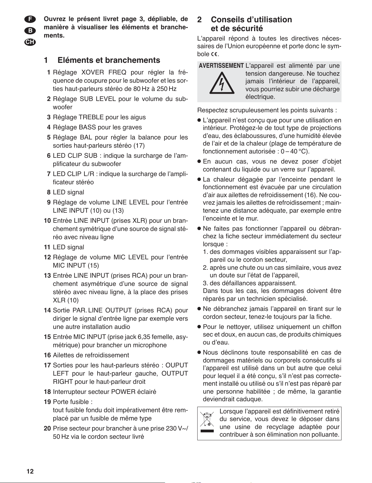
Ouvrez le présent livret page 3, dépliable, de
manière à visualiser les éléments et branche-
ments.
1 Eléments et branchements
1Réglage XOVER FREQ pour régler la fré-
quence de coupure pour le subwoofer et les sor-
ties haut-parleurs stéréo de 80 Hz à 250 Hz
2Réglage SUB LEVEL pour le volume du sub-
woofer
3Réglage TREBLE pour les aigus
4Réglage BASS pour les graves
5Réglage BAL pour régler la balance pour les
sorties haut-parleurs stéréo (17)
6LED CLIP SUB : indique la surcharge de lʼam-
plificateur du subwoofer
7LED CLIP L/R : indique la surcharge de lʼampli-
ficateur stéréo
8LED signal
9Réglage de volume LINE LEVEL pour lʼentrée
LINE INPUT (10) ou (13)
10 Entrée LINE INPUT (prises XLR) pour un bran-
chement symétrique dʼune source de signal sté-
réo avec niveau ligne
11 LED signal
12 Réglage de volume MIC LEVEL pour lʼentrée
MIC INPUT (15)
13 Entrée LINE INPUT (prises RCA) pour un bran-
chement asymétrique dʼune source de signal
stéréo avec niveau ligne, à la place des prises
XLR (10)
14 Sortie PAR. LINE OUTPUT (prises RCA) pour
diriger le signal dʼentrée ligne par exemple vers
une autre installation audio
15 Entrée MIC INPUT (prise jack 6,35 femelle, asy-
métrique) pour brancher un microphone
16 Ailettes de refroidissement
17 Sorties pour les haut-parleurs stéréo : OUPUT
LEFT pour le haut-parleur gauche, OUTPUT
RIGHT pour le haut-parleur droit
18 Interrupteur secteur POWER éclairé
19 Porte fusible :
tout fusible fondu doit impérativement être rem-
placé par un fusible de même type
20 Prise secteur pour brancher à une prise 230 V~/
50 Hz via le cordon secteur livré
2 Conseils dʼutilisation
et de sécurité
Lʼappareil répond à toutes les directives néces-
saires de lʼUnion européenne et porte donc le sym-
bole .
Respectez scrupuleusement les points suivants :
GLʼappareil nʼest conçu que pour une utilisation en
intérieur. Protégez-le de tout type de projections
dʼeau, des éclaboussures, dʼune humidité élevée
de lʼair et de la chaleur (plage de température de
fonctionnement autorisée : 0 – 40 °C).
GEn aucun cas, vous ne devez poser dʼobjet
contenant du liquide ou un verre sur lʼappareil.
GLa chaleur dégagée par lʼenceinte pendant le
fonctionnement est évacuée par une circulation
dʼair aux ailettes de refroidissement (16). Ne cou-
vrez jamais les ailettes de refroidissement ; main-
tenez une distance adéquate, par exemple entre
lʼenceinte et le mur.
GNe faites pas fonctionner lʼappareil ou débran-
chez la fiche secteur immédiatement du secteur
lorsque :
1. des dommages visibles apparaissent sur lʼap-
pareil ou le cordon secteur,
2. après une chute ou un cas similaire, vous avez
un doute sur lʼétat de lʼappareil,
3. des défaillances apparaissent.
Dans tous les cas, les dommages doivent être
réparés par un technicien spécialisé.
GNe débranchez jamais lʼappareil en tirant sur le
cordon secteur, tenez-le toujours par la fiche.
GPour le nettoyer, utilisez uniquement un chiffon
sec et doux, en aucun cas, de produits chimiques
ou dʼeau.
GNous déclinons toute responsabilité en cas de
dommages matériels ou corporels consécutifs si
lʼappareil est utilisé dans un but autre que celui
pour lequel il a été conçu, sʼil nʼest pas correcte-
ment installé ou utilisé ou sʼil nʼest pas réparé par
une personne habilitée ; de même, la garantie
deviendrait caduque.
Lorsque lʼappareil est définitivement retiré
du service, vous devez le déposer dans
une usine de recyclage adaptée pour
contribuer à son élimination non polluante.
AVERTISSEMENT Lʼappareil est alimenté par une
tension dangereuse. Ne touchez
jamais lʼintérieur de lʼappareil,
vous pourriez subir une décharge
électrique.
12
F
B
CH
All manuals and user guides at all-guides.com
3 Possibilités dʼutilisation
Les PSUB-12AKA et PSUB-15AKA sont des
enceintes actives subwoofer puissantes proposées
dans des caissons bois solides. Les enceintes pos-
sèdent un amplificateur final stéréo intégré, deux
canaux dʼentrée mixables et des réglages de tona-
lité. Cela rend plus facile une installation audio
compacte : seules deux enceintes pour la restitu-
tion des médiums-aigus sont nécessaires (par
exemple PAB-306 ou PAB-308 de “img Stage
Line”).
Les enceintes subwoofer disposent dʼun filtre
avec fréquence de coupure réglable (80 – 250 Hz)
qui répartit le signal sur le subwoofer et les
enceintes stéréo reliées.
Les amplificateurs sont dotés dʼun limiteur
contre les surcharges et de circuits de protection
contre le court-circuit et la surchauffe.
Lʼinsert pour pied sur la face supérieure du sub-
woofer permet un montage dʼune enceinte.
4 Positionnement
Placez lʼenceinte subwoofer sur une base fixe. Si
vous utilisez un seul subwoofer, le positionnement
précis au milieu entre les enceintes stéréo nʼest
pas primordial puisque les fréquences très basses
ne peuvent pas être localisées avec précision. Ne
le placez pas trop près des murs ou dans les coins
car cela modifie la plage de fréquences et
empêche la dissipation de chaleur de lʼamplifica-
teur intégré.
Il est possible de monter une autre enceinte sur
le subwoofer. Mettez un adaptateur de diamètre de
tube de 35 mm (par exemple dans la série PAST de
“img Stage Line”) dans lʼinsert pour pied sur la face
supérieure du subwoofer et fixez une enceinte
avec un insert sur la face inférieure.
5 Branchement
Avant dʼeffectuer les branchements ou de modifier
les branchements existants, éteignez le subwoofer
et les appareils à relier.
5.1 Branchement de la source de signal
Reliez une source de signal avec niveau ligne
(par exemple lecteur CD, sortie dʼune table de
mixage) aux prises RCA LINE INPUT (13). Les
entrées sont configurées pour des signaux stéréo
(R : canal droit, L : canal gauche). Un signal mono
est créé en interne pour le subwoofer à partir des
deux canaux stéréo de la source de signal.
Si une source de signal avec signal de sortie
symétrique est disponible (par exemple sortie
dʼune table de mixage), reliez cette source aux
entrées XLR (10). Vous trouverez la configuration
de la prise sur le schéma 2.
Les entrées RCA et XLR ne peuvent pas être uti-
lisées simultanément !
Pour relier un microphone, utilisez la prise jack
6,35 MIC INPUT (15). Elle est asymétrique. Vous
trouverez la configuration de la fiche sur le schéma
3. Pour relier des microphones avec signal de sor-
tie symétrique, utilisez un adaptateur.
5.2 Sortie signal
Le signal des entrées ligne (10, 13) est présent aux
prises RCA PAR.LINE OUTPUT (14). On peut relier
ici par exemple une autre installation audio ou un
enregistreur.
5.3 Haut-parleurs stéréo
Reliez deux enceintes pour la restitution des
médiums-aigus avec une impédance de 8 Ω au
moins, par exemple PAB-306, aux prises HP (17)
OUTPUT LEFT (enceinte gauche) et OUTPUT
RIGHT (enceinte droite). La configuration de la
fiche est indiquée sur le schéma 4. Si plusieurs
enceintes sont branchées ensemble à une sortie,
lʼimpédance totale des enceintes ne doit pas être
inférieure à 8 Ω par sortie.
Tournez vers la droite une fiche haut-parleur
après lʼavoir insérée dans la prise jusquʼà ce quʼelle
sʼenclenche. Pour pouvoir la retirer ultérieurement,
tirez sur le levier de verrouillage et tournez la fiche
vers la gauche.
Lorsque vous effectuez le branchement des
enceintes, veillez à respecter la même polarité
pour les deux enceintes.
13
F
B
CH
All manuals and user guides at all-guides.com

5.4 Alimentation
Reliez le cordon secteur livré à la prise (20) et lʼau-
tre extrémité du cordon secteur à une prise secteur
230 V~/50 Hz.
6 Utilisation
Conseil : Pour éviter tout bruit fort de commutation,
allumez toujours en premier les sources de signal
reliées puis le subwoofer. Eteignez les appareils
dans lʼordre inverse.
1) Avant la première mise en service, tournez
dʼabord les réglages SUB LEVEL (2), LINE
LEVEL (9) et MIC LEVEL (12) sur le minimum
(butée de gauche). Pour le régalage de base,
mettez sur la position médiane les réglages de
tonalité TREBLE (3) et BASS (4) et le réglage de
balance BAL (5).
2) Allumez lʼappareil avec lʼinterrupteur POWER
(18). Lʼinterrupteur brille.
3) Si une source de signal est reliée à une entrée
LINE INPUT (10, 13), réglez le volume souhaité
avec le réglage LINE LEVEL (9). Tournez le
réglage de telle sorte que le son ne soit pas
encore distordu et que la LED CLIP L/R (7) ne
brille pas.
4) Si un microphone est relié, mixez son signal
avec le réglage MIC LEVEL (12) et si besoin,
diminuez le niveau du signal ligne avec le
réglage LINE LEVEL (9).
ATTENTION ! Pour éviter tout sifflement de lar-
sen, ne tenez pas le microphone en direction du
haut-parleur ou trop près. Des effets larsen peu-
vent également survenir si le volume réglé est
trop élevé. Dans ce cas ou si la LED CLIP L/R
(7) brille, diminuez le volume micro avec le
réglage MIC LEVEL (12).
5) Avec les deux réglages TREBLE (3) et BASS
(4), réglez la tonalité. Mixez la part de graves
souhaitée avec le réglage de volume du sub-
woofer SUB LEVEL (2). Tournez le réglage de
telle sorte que le son ne soit pas encore dis-
tordu. Si la LED CLIP SUB (6) brille, lʼamplifica-
teur du subwoofer est en surcharge. Dans ce
cas, tournez le réglage en arrière ou diminuez le
volume du signal dʼentrée.
Avec le réglage XOVER FREQ (1), réglez la
fréquence de coupure (80 – 250 Hz) de telle
sorte que le subwoofer complète de manière
optimale le son des enceintes stéréo reliées.
6) Si besoin, corrigez la balance de volume des
enceintes stéréo avec le réglage BAL (5).
7) Après utilisation, éteignez lʼappareil avec lʼinter-
rupteur POWER.
ATTENTION Ne réglez pas le volume trop fort. Un
volume trop élevé peut, à long terme,
générer des troubles de lʼaudition.
Lʼoreille sʼhabitue à des volumes éle-
vés et ne les perçoit plus comme tels
au bout dʼun certain temps. Nous
vous conseillons donc de régler le
volume et de ne plus le modifier.
14
F
B
CH
All manuals and user guides at all-guides.com

15
F
B
CH
Notice dʼutilisation protégée par le copyright de MONACOR ®INTERNATIONAL GmbH & Co. KG. Toute
reproduction même partielle à des fins commerciales est interdite.
Tout droit de modification réservé.
Modèle PSUB-12AKA PSUB-15AKA
Puissance amplificateur
Puissance RMS stéréo (sous 8 Ω)
Puissance RMS subwoofer
Puissance crête totale
2 × 150 W
500 W
1200 W
Bande passante (fréquence coupure variable)
Subwoofer
Stéréo
30 – 80 … 250 Hz
80 … 250 – 20 000 Hz
Rapport signal sur bruit > 74 dB
Haut-parleur subwoofer
Pression sonore max.
∅30 cm (12″)
123 dB
∅38 cm (15″)
124 dB
Entrée LINE INPUT (RCA)
Sensibilité
Tension dʼentrée max.
Impédance
880 mV
7V
10 kΩ
Entrée LINE INPUT (XLR)
Sensibilité
Tension dʼentrée max.
Impédance
880 mV
7V
10 kΩ
Entrée MIC INPUT (jack 6,35, asym)
Sensibilité
Tension dʼentrée max.
Impédance
30 mV
850 mV
1kΩ
Sorties haut-parleurs
Impédance minimale de charge
Branchement
8Ω
prises HP (compatible speakON®)
Température fonc. 0 – 40 °C
Alimentation
Consommation max.
230 V~/50 Hz
1870 VA
Dimensions (L × H × P)
Poids
460 × 380 × 455 mm
28 kg
600 × 500 × 580 mm
48 kg
7 Caractéristiques techniques
All manuals and user guides at all-guides.com

A pagina 3, se aperta completamente, vedrete
tutti gli elementi di comando e i collegamenti
descritti.
1 Elementi di comando
e collegamenti
1Regolatore XOVER FREQ per impostare la fre-
quenza di taglio per il subwoofer e per le uscite
stereo degli altoparlanti da 80 Hz a 250 Hz
2Regolatore SUB LEVEL per il volume del sub-
woofer
3Regolatore toni TREBLE per gli alti
4Regolatore toni BASS per i bassi
5Regolatore BAL per impostare il bilanciamento
per le uscite stereo per altoparlanti (17)
6LED CLIP SUB; indica il sovrapilotaggio del-
lʼamplificatore del subwoofer
7LED CLIP L/R; indica il sovrapilotaggio dellʼam-
plificatore stereo
8LED dei segnali
9Regolatore volume LINE LEVEL per lʼingresso
LINE INPUT (10) o (13)
10 Ingresso LINE INPUT (prese XLR) per il colle-
gamento bilanciato di una fonte stereo con
livello line
11 LED dei segnali
12 Regolatore volume MIC LEVEL per lʼingresso
MIC INPUT (15)
13 Ingresso LINE INPUT (prese RCA) per il colle-
gamento sbilanciato di una fonte stereo con
livello line, in alternativa alle prese XLR (10)
14 Uscita PAR. LINE OUTPUT (prese RCA) per
inoltrare il segnale Line dʼingresso, p. es. ad un
ulteriore impianto di altoparlanti
15 Ingresso MIC INPUT (presa jack 6,3 mm, sbi-
lanciata) per il collegamento di un microfono
16 Alette di raffreddamento
17 Uscita per gli altoparlanti stereo;
OUTPUT LEFT per lʻaltoparlante sinistro,
OUTPUT RIGHT per quello destro
18 Interruttore rete POWER, illuminato
19 Portafusibile
Sostituire un fusibile difettoso solo con uno dello
stesso tipo.
20 Presa per il collegamento con una presa di rete
(230 V~/50 Hz) tramite il cavo in dotazione
2 Avvertenze di sicurezza
Lʼapparecchio è conforme a tutte le direttive rile-
vanti dellʼUE e pertanto porta la sigla .
Si devono osservare assolutamente anche i seguenti
punti:
GUsare lʼapparecchio solo allʼinterno di locali e pro-
teggerlo dallʼacqua gocciolante e dagli spruzzi
dʼacqua, da alta umidità dellʼaria e dal calore
(temperatura dʼimpiego ammessa fra 0 e 40 °C).
GNon depositare sullʼapparecchio dei contenitori
riempiti di liquidi, p. es. bicchieri.
GIl calore prodotto durante il funzionamento viene
dissipato alle alette di raffreddamento (16)
mediante circolazione dellʼaria. Perciò non coprire
le alette e mantenere una certa distanza p. es. da
una parete.
GNon mettere in funzione lʼapparecchio e staccare
subito la spina rete se:
1. lʼapparecchio o il cavo rete presentano dei
danni visibili;
2. dopo una caduta o dopo eventi simili sussiste
il sospetto di un difetto;
3. lʼapparecchio non funziona correttamente.
Per la riparazione rivolgersi sempre ad unʼoffi-
cina competente.
GStaccare il cavo rete afferrando la spina, senza
tirare il cavo.
GPer la pulizia usare solo un panno morbido,
asciutto; non impiegare in nessun caso acqua o
prodotti chimici.
GNel caso dʼuso improprio, dʼinstallazione sba-
gliata, dʼimpiego scorretto o di riparazione non a
regola dʼarte dellʼapparecchio, non si assume
nessuna responsabilità per eventuali danni con-
sequenziali a persone o a cose e non si assume
nessuna garanzia per lʼapparecchio.
Se si desidera eliminare lʼapparecchio
definitivamente, consegnarlo per lo smalti-
mento ad unʼistituzione locale per il rici-
claggio.
AVVERTIMENTO Lʼapparecchio è alimentato con
pericolosa tensione di rete. Non
intervenire mai personalmente al
suo interno: Esiste il pericolo di
una scarica elettrica.
16
I
All manuals and user guides at all-guides.com
all-guides.com

3 Possibilità dʻimpiego
Le PSUB-12AKA e PSUB-15AKA sono casse sub-
woofer attive e potenti in contenitori robusti di
legno. Le casse sono equipaggiate con un amplifi-
catore finale stereo, con due canali dʼingresso
miscelabili e con regolatori toni. Per la creazione
semplice di un impianto compatto di altoparlanti
bastano due casse per i medi/alti (p. es. PAB-306 o
PAB-308 di “img Stage Line”).
Le casse subwoofer dispongono di un filtro di
frequenze con frequenza di taglio impostabile (80 –
250 Hz), che divide il segnale fra il subwoofer e gli
altoparlanti stereo collegati.
Gli amplificatori sono equipaggiati con un limiter
per escludere il sovraccarico e con circuiti protettivi
contro cortocircuiti e surriscaldamento.
La boccola per stativo sul lato superiore del sub-
woofer permette il montaggio di una cassa acu-
stica.
4 Collocamento
Posizionare la cassa subwoofer su un fondo sta-
bile. Se si usa un solo subwoofer, lʼesatta posizione
nel centro fra gli altoparlanti stereo non è decisiva
dato che le frequenze molto basse del subwoofer
non possono essere localizzate con precisione.
Tuttavia, non posizionare il subwoofer troppo vicino
a pareti o in angoli per non sfalsare la risposta in
frequenza e per non ostacolare la dissipazione del
calore.
Sulla cassa del subwoofer si può montare unʼal-
tra cassa. Per fare ciò, inserire un tubo intermedio
con diametro di 35 mm (p. es. della serie PAST di
“img Stage Line”) nella boccola per stativi sul lato
superiore del subwoofer e fissare una cassa acu-
stica con boccola per stativi sul lato inferiore.
5 Collegamento
Prima di effettuare o modificare i collegamenti esi-
stenti spegnere il subwoofer e gli apparecchi da
collegare.
5.1 Collegare la fonte di segnali
Collegare una fonte di segnali con livello Line
(p. es. lettore CD, uscita mixer) con le prese RCA
LINE INPUT (13). Gli ingressi sono previsti per
segnali stereo (R = canale destro, L = canale sini-
stro). Dai due canali stereo della fonte di segnali si
crea internamento un segnale mono per il subwoo-
fer.
Se è presente una fonte di segnali con segnale
bilanciato dʼuscita (p. es. uscita del mixer), colle-
garla con gli ingressi XLR (10). I contatti della presa
sono rappresentati nella fig. 2.
Gli ingressi RCA e XLR non si possono usare
contemporaneamente!
Un microfono può essere collegato con la presa
jack MIC INPUT (15). La presa è prevista per
segnali sbilanciati. I contatti del connettore sono
rappresentati nella fig. 3. I microfoni con segnale
bilanciato dʼuscita sono da collegare per mezzo di
un adattatore.
5.2 Uscita dei segnali
Alle prese RCA PAR. LINE OUTPUT (14) è pre-
sente il segnale degli ingressi Line (10, 13). Qui si
può collegare per esempio unʼulteriore impianto di
altoparlanti o un registratore.
5.3 Altoparlanti stereo
Collegare due casse acustiche per la riproduzione
dei medi/alti con impedenza minima di 8 Ω, p. es.
PAB-306, con le prese per altoparlanti (17) OUT-
PUT LEFT (altoparlante sinistro) e OUTPUT
RIGHT (altoparlante destro). I contatti del connet-
tore sono rappresentati nella fig. 4. Se più altopar-
lanti sono collegati con unʼuscita, lʼimpedenza glo-
bale per lʼuscita non deve essere inferiore a 8 Ω.
Dopo aver inserito il connettore per altoparlanti
nella presa, girarlo a destro fino allo scatto. Per
staccarlo successivamente, tirare indietro la leva di
sicurezza e girare il connettore a sinistra.
Collegando gli altoparlanti rispettare la mede-
sima polarità per i due altoparlanti.
17
I
All manuals and user guides at all-guides.com

5.4 Alimentazione
Collegare il cavo in dotazione con la presa (20) e
inserire la spina in una presa di rete (230 V~/
50 Hz).
6 Funzionamento
N. B.: Per evitare i rumori di commutazione, accen-
dere prima le fonti collegate di segnali e solo suc-
cessivamente il subwoofer. Per spegnere, proce-
dere in modo inverso.
1) Prima della prima accensione portare i regola-
tori SUB LEVEL (2), LINE LEVEL (9) e MIC
LEVEL (12) momentaneamente sul minimo
(arresto a sinistra). Per lʼimpostazione base por-
tare i regolatori dei toni TREBLE (3) e BASS (4)
nonché quello del bilanciamento BAL (5) in posi-
zione centrale.
2) Accendere lʼapparecchio con lʼinterruttore
POWER (18). Sʼillumina lʻinterruttore.
3) Se allʼingresso LINE INPUT (10, 13) è collegata
una fonte di segnali, impostare il volume con il
regolatore LINE LEVEL (9). Aprire il regolatore
solo al punto da non distorcere i toni e senza che
il LED CLIP L/R (7) si accenda.
4) Se è collegato un microfono, aggiungere il suo
segnale con il regolatore MIC LEVEL (12) e, se
necessario, ridurre il livello del segnale line con
il regolatore LINE LEVEL (9).
ATTENZIONE! Per escludere un fischio di feed-
back, non tenere il microfono in direzione dellʼal-
toparlante e non troppo vicino allo stesso. Anche
con un volume impostato troppo alto si può
manifestare il feedback. In questo caso o se il
LED CLIP L/R (7) si accende, con il regolatore
MIC LEVEL (12) impostare un volume minore
per il microfono.
5) Impostare i toni con i regolatori TREBLE (3) e
BASS (4). Aggiungere la parte molto bassa del
subwoofer con il suo regolatore di volume SUB
LEVEL (2). Aprire il regolatore al punto da non
distorcere i toni. Se si accende il LED CLIP SUB
(6), significa che lʼamplificatore del subwoofer è
sovrapilotato. In questo caso ridurre il regolatore
oppure ridurre il volume del segnale dʻingresso.
Con il regolatore XOVER FREQ (1) impo-
stare la frequenza di taglio (80 – 250 Hz) così
che il subwoofer completi in modo ottimale i toni
degli altoparlanti stereo collegati.
6) Se necessario, con il regolatore BAL (5) correg-
gere il bilanciamento del volume degli altopar-
lanti stereo.
7) Dopo lʼuso spegnere lʼapparecchio con lʼinterrut-
tore POWER.
ATTENZIONE! Mai tenere molto alto il volume. A
lungo andare, il volume ecces-
sivo può procurare danni allʼudito!
Lʼorecchio si abitua agli alti volumi
e dopo un certo tempo non se
ne rende più conto. Perciò non
aumentare il volume successiva-
mente.
18
I
All manuals and user guides at all-guides.com

19
I
La MONACOR ®INTERNATIONAL GmbH & Co. KG si riserva ogni diritto di elaborazione in qualsiasi forma
delle presenti istruzioni per lʼuso. La riproduzione – anche parziale – per propri scopi commerciali è vietata.
Con riserva di modifiche tecniche.
Modello PSUB-12AKA PSUB-15AKA
Potenza degli amplificatori
Potenza efficace stereo (con 8 Ω)
Potenza efficace subwoofer
Potenza globale di picco
2 × 150 W
500 W
1200 W
Gamma di frequenze (frequenza di taglio variabile)
subwoofer
stereo
30 – 80 … 250 Hz
80 … 250 – 20 000 Hz
Rapporto S/R > 74 dB
Altoparlante subwoofer
Pressione sonora nominale max.
∅30 cm (12″)
123 dB
∅38 cm (15″)
124 dB
Ingresso LINE INPUT (RCA)
Sensibilità
Tensione max. dʼingresso
Impedenza
880 mV
7V
10 kΩ
Ingresso LINE INPUT (XLR)
Sensibilità
Tensione max. dʼingresso
Impedenza
880 mV
7V
10 kΩ
Ingresso MIC INPUT (jack 6,3 mm, sbil.)
Sensibilità
Tensione max. dʼingresso
Impedenza
30 mV
850 mV
1kΩ
Uscita altoparlanti
Impedenza min. di carico
Collegamento
8Ω
Prese per altoparlanti (compatibili speakON®)
Temperatura dʻesercizio 0 – 40 °C
Alimentazione
Potenza assorbita max.
230 V~/50 Hz
1870 VA
Dimensioni (l × h × p)
Peso
460 × 380 × 455 mm
28 kg
600 × 500 × 580 mm
48 kg
7 Dati tecnici
All manuals and user guides at all-guides.com

Op de uitklapbare pagina 3 vindt u een over-
zicht van alle bedieningselementen en de aan-
sluitingen.
1 Overzicht van de bedienings-
elementen en aansluitingen
1Regelaar XOVER FREQ om de scheidingsfre-
quentie voor de subwoofer en de stereoluid-
sprekeruitgangen van 80 Hz tot 250 Hz in te
stellen
2Regelaar SUB LEVEL voor het volume van de
subwoofer
3Klankregelaar TREBLE voor de hoge tonen
4Klankregelaar BASS voor de lage tonen
5Regelaar BAL voor het instellen van de balans
van de stereoluidsprekeruitgangen (17)
6Led CLIP SUB; geeft de oversturing van de
subwooferversterker aan
7Led CLIP L/R; geeft de oversturing van de ste-
reoversterker aan
8Signaal-led
9Volumeregelaar LINE LEVEL voor de ingang
LINE INPUT (10) of (13)
10 Ingang LINE INPUT (XLR-jacks) voor gebalan-
ceerde aansluiting van een stereosignaalbron
met lijnniveau
11 Signaal-led
12 Volumeregelaar MIC LEVEL voor de ingang
MIC INPUT (15)
13 Ingang LINE INPUT (cinch-jacks) voor de onge-
balanceerde aansluiting van een stereosignaal-
bron met lijnniveau, in de plaats van de XLR-
jacks (10)
14 Uitgang PAR. LINE OUTPUT (cinch-jacks) om
lijningangssignaal door te sturen, bv. naar een
volgende luidsprekerinstallatie
15 Ingang MIC INPUT (6,3 mm-stekkerbus, onge-
balanceerd geschakeld) voor het aansluiten van
een microfoon
16 Koelribben
17 Uitgangen voor de stereoluidspreker; OUTPUT
LEFT voor de linker, OUTPUT RIGHT voor de
rechter luidspreker
18 Verlichte POWER-schakelaar
19 Houder voor de netzekering
Vervang een gesmolten zekering uitsluitend
door een zekering van hetzelfde type.
20 POWER-jack voor aansluiting op een stopcon-
tact (230 V~/50 Hz) via het bijgeleverde nets-
noer
2 Veiligheidsvoorschriften
Het apparaat is in overeenstemming met alle rele-
vante EU-Richtlijnen en is daarom met geken-
merkt.
Let bij ingebruikname ook zeker op het volgende:
GHet apparaat is enkel geschikt voor gebruik bin-
nenshuis; vermijd druip- en spatwater, plaatsen
met een hoge vochtigheid en uitzonderlijk warme
plaatsen (toegestaan omgevingstemperatuurbe-
reik: 0 – 40 °C).
GPlaats geen bekers met vloeistof zoals drinkgla-
zen etc. op het apparaat.
GDe warmte die tijdens het gebruik ontstaat, wordt
door luchtcirculatie aan de koelribben (16) afge-
geven. Dek ze daarom niet af, en houd vol-
doende afstand bv. tot een muur.
GSchakel het apparaat niet in of trek onmiddellijk
de stekker uit het stopcontact,
1. wanneer het apparaat of het netsnoer zicht-
baar beschadigd is,
2. wanneer er een defect zou kunnen optreden
nadat het apparaat bijvoorbeeld is gevallen,
3. wanneer het apparaat slecht functioneert.
Het apparaat moet in elk geval worden hersteld
door een gekwalificeerd vakman.
GTrek de stekker nooit met het snoer uit het stop-
contact, maar met de stekker zelf.
GVerwijder het stof met een droge, zachte doek.
Gebruik zeker geen water of chemicaliën.
GIn geval van ongeoorloofd of verkeerd gebruik,
verkeerde installatie, foutieve bediening of van
herstelling door een niet-gekwalificeerd persoon
vervalt de garantie en de verantwoordelijkheid
voor hieruit resulterende materiële of lichamelijke
schade.
Wanneer het apparaat definitief uit bedrijf
wordt genomen, bezorg het dan voor
milieuvriendelijke verwerking aan een
plaatselijk recyclagebedrijf.
WAARSCHUWING De netspanning van de appa-
raat is levensgevaarlijk. Open
het apparaat niet, want u loopt
het risico van een elektrische
schok.
20
NL
B
All manuals and user guides at all-guides.com
This manual suits for next models
3
Table of contents
Languages:
Other IMG STAGE LINE Subwoofer manuals

IMG STAGE LINE
IMG STAGE LINE MCX-200/SW User manual

IMG STAGE LINE
IMG STAGE LINE CALDERA-B10 User manual

IMG STAGE LINE
IMG STAGE LINE PSUB-18L User manual

IMG STAGE LINE
IMG STAGE LINE SOUND-100SUB User manual

IMG STAGE LINE
IMG STAGE LINE SOUND -100SUB User manual

IMG STAGE LINE
IMG STAGE LINE PSUB-15AKA User manual

IMG STAGE LINE
IMG STAGE LINE PSUB-418AK User manual

IMG STAGE LINE
IMG STAGE LINE PSUB-418AK User manual

IMG STAGE LINE
IMG STAGE LINE PSUB-215AK User manual

IMG STAGE LINE
IMG STAGE LINE PSUB-18L User manual


