IMI Bimba BPGS Series User manual

BPGS PNEUMATIC
GRIPPER SYSTEM
BPGS10 and BPGS11
User Manual
We make
things MOVE
®

BPGS PNEUMATIC GRIPPER SYSTEM
User Manual
BIM-BPGSM-0519 Rev 1 | For Technical Assistance: 800-442-4622
2
WARNING
Using the equipment in a manner not specified in this manual can impair the safety of the equipment.
Technical support is available from:
Bimba Manufacturing Company
25150 S Governors Hwy University Park, Illinois 60484
Phone: 708-534-8544 Toll Free: 800-44-BIMBA Fax: 708-235-2014
SCOPE OF THIS MANUAL
This instruction manual supports Bimba standard components only. If special components, including but
not limited to serial hubs, power supplies, and drivers, are included based on a customer’s specifications
or special request, it is the customer’s responsibility to consult support materials and technical support
specific to these special components provided by the third party manufacturers. Bimba assumes no liability
for misuse, misapplication, or support for components that are not the Bimba brand.

BPGS PNEUMATIC GRIPPER SYSTEM
User Manual
BIM-BPGSM-0519 Rev 1 | For Technical Assistance: 800-442-4622
3
Port Size and Operation 4
Gripper Unlock 4
Jaw Removal 4
Jaw Replacement 5
Setting Jaw Open Angle 6
Installing a Side Plate or Indirect Sensor 7
Pad Replacement 8
Calibrating In-Direct Sensor 8
Installing an In-Pad Sensor 9
Cleaning and Maintenance 10
Quality Assurance Requirements 10
Specifications 10
TABLE OF CONTENTS

BPGS PNEUMATIC GRIPPER SYSTEM
User Manual
BIM-BPGSM-0519 Rev 1 | For Technical Assistance: 800-442-4622
4
PORT SIZE AND OPERATION
Gripper open
Gripper close letter “C” to identify part
1. Ports are available in 1/8" NPS or 1/8 Rc.
GRIPPER UNLOCK
1. Release jaw by using a hex key or flat screwdriver and pushing on drive pin through slot in side plate
JAW REMOVAL
1. Unlock gripper as shown in step above and remove pad(s) from existing jaws. Set a side for reassembly.
2. Top jaw should always be removed first. Remove Socket Head Cap Screw (SHCS) from side plate or indirect
sensor. Rotate side plate/sensor up to about 45° and remove side plate/sensor from gripper. Set SHCS and
Side Plate/Sensor aside for re-assembly. Remove bumper from gripper.
3. Remove jaw from gripper and flip gripper over to remove other jaw

BPGS PNEUMATIC GRIPPER SYSTEM
User Manual
BIM-BPGSM-0519 Rev 1 | For Technical Assistance: 800-442-4622
5
4. Remove SHCS from side plate/sensor. Rotate side plate/sensor up to about 45° angle and remove from gripper.
Set SHCS and Side Plate/Sensor aside for re-assembly.
5. Remove bushing from lower jaw using a small flat screwdriver or hex key and set aside for re-assembly. Lower jaw
should be rotated completely down before removal. Lift up on front of jaw by pad so there is an angle between
jaw and frame. Remove lower jaw from gripper.
JAW REPLACEMENT
1. For lower jaws (B10151, B11105, B11105-01, B11105-02, B11106, B11106-01, B11106-02, B11103, B12978,
B12978-01, B12978-02, B12985, B12985-01, B12985-02): Apply grease to cam and inside of jaw. Angle new
jaw so that tail of jaw goes in pocket of frame. Align pivot hole with boss and drive pin with the bottom side of the
cam slot. Carefully slide jaw over boss and onto gripper. Replace bushing over pin and into cam. Apply grease to
outside of jaw.
2. Refer to steps for "Installing a Side Plate or Indirect Sensor"
3. Flip gripper over for top jaw installation
Tail of jaw in pocket
Angle

BPGS PNEUMATIC GRIPPER SYSTEM
User Manual
BIM-BPGSM-0519 Rev 1 | For Technical Assistance: 800-442-4622
6
5. Refer to "Setting Jaw Open Angle" step 2 to set bumper position. Refer to "Gripper Unlock" for installing a Side
Plate or Indirect Sensor.
4. For upper jaws: Apply grease to cam and inside of jaw. Replace bushing over drive pin and onto gripper. Align
hole in jaw with boss on frame and cam with bushing. Slide jaw over boss and drive pin so that jaw rests on
gripper. Apply grease to outside of jaw.
SETTING JAW OPEN ANGLE
1. Look for bumper which should be on the upper jaw side. Remove M5X12mm SHCS from side plate. If indirect
sensor is in place of side plate remove M5X30mm from indirect sensor. Rotate side plate/sensor up to about a
45° and remove from gripper. Set SHCS and Side Plate/Sensor aside for re-assembly. Remove bumper from
gripper.
2. Insert bumper into new position, based on required open jaw angle. Bumpers should only be on the top jaw side
of gripper. Jaws do not need to be removed to change bumper position. Insert bumper into frame and insure
bumper is seated properly.
22° Open Jaw Angle 45° Open Jaw Angle 70° Open Jaw Angle

BPGS PNEUMATIC GRIPPER SYSTEM
User Manual
BIM-BPGSM-0519 Rev 1 | For Technical Assistance: 800-442-4622
7
INSTALLING A SIDE PLATE OR INDIRECT SENSOR
1. With the Side Plate at 45°, align pins of side plate with slots of frame. Slide pins into slot. When pins are fully
seated, rotate side plate and slide down onto frame.
2. If an Indirect Sensor is to be installed, move brass bushing in sensor to align with drive pin in gripper. This must
be done to correctly install sensor. Align dowel pins with slots of frame. Once pins are fully into slots, rotate sensor
down onto frame. As rotation begins make sure bushing and drive pin are still aligned.
Note: Whenever any part of the gripper is replaced including pads the sensor will need to be recalibrated, see
"Calibrating In-Direct Sensor".
3. Clean and apply Loctite 262 or equivalent to M5 X 12mm SHCS for side plate or M5 X 30mm SHCS for sensor.
Insert through side plate/sensor and into frame. Tighten M5 SHCS to 72in-lb.
Side Plate Indirect Sensor

BPGS PNEUMATIC GRIPPER SYSTEM
User Manual
BIM-BPGSM-0519 Rev 1 | For Technical Assistance: 800-442-4622
8
PAD REPLACEMENT
1. Unlock jaws on gripper & open jaws to get access to pads. Side plates/sensor DO NOT need to be removed.
Refer to Gripper Unlock.
2. Remove M5X8mm SHCS from jaw.
3.
3. Apply Loctite 262 to M5 X 8mm SHCS and insert into one of the jaws. Take replacement pads and insert it into
the opposite side of the jaw with SHCS sticking out. Thread SHCS into pad and tighten to 72in-lb.Repeat step
for other jaw. Chisel jaws only require one pad
CALIBRATING IN-DIRECT SENSOR
Sensor must be calibrated whenever any part of the gripper is replaced including pads.
1. Part Present
a.) To program the sensor for a particular material thickness, apply air to the gripper and grip on the material
thickness which is to be used for the particular job. With an object such as a small Allen wrench, press the
button until the Red LED corresponding to the material range of the job lights as shown on the label.
b.) Verify calibration:
(1) Close the gripper with no material between the pads. The LED should be o.
(2) Close the gripper on a single blank of material. The Red LED corresponding to your material range
should be on.

BPGS PNEUMATIC GRIPPER SYSTEM
User Manual
BIM-BPGSM-0519 Rev 1 | For Technical Assistance: 800-442-4622
9
2. Double Blank
1) To program the sensor for a particular material thickness, apply air to the gripper and grip on the material
thickness which is to be used for the particular job. With an object such as a small Allen wrench, press the
button until the Red LED(s) corresponding to the material range of the job lights as shown on the label.
2) Verify calibration:
(a.) Close the gripper with no material between the pads. The LED(s) should be o.
(b.) Close the gripper on a single blank of material. The Red LED(s) corresponding to you material range should
be on.
INSTALLING AN IN-PAD SENSOR
1. If an In-Pad Sensor is to be installed, it goes on top of the side plate assembly. Wrap sensor cable through
holder and align holes on side plate. Clean and apply Red Loctite 262 or equivalent to 2X M5 X 10mm SHCS
and thread thru sensor into side plate. Tighten both SHCS to 36in-lb.
2. Shim is only used for part numbers listed. If a shim is to be used on an angle pad, smaller tabs go on the
narrow side of the pads.
Small Tabs
BPGS10RXXXXX1XXX
BPGS10FXXXXX1XXX
BPGS10CXXXXX1XXX
BPGS10DXXXXX4XXX
BPGS10EXXXXX7XXX
BPGS10SXXXXX1XXX
BPGS10TXXXXX4XXX
BPGS10UXXXXX7XXX
BPGS10VXXXXX1XXX
BPGS10WXXXXX4XXX
BPGS10YXXXXX7XXX

BPGS PNEUMATIC GRIPPER SYSTEM
User Manual
BIM-BPGSM-0519 Rev 1 | For Technical Assistance: 800-442-4622
10
Gripper Throat Depth
Inch (mm)
Flange Height
Inch (mm)
Working Pressure Double Sided Grip
Force Up To
Actuation Time
BPGS10C .76 19.3 1.27 (32.3) 60 psi (413kPa) Min. –
100 psi (689 kPa) Max.
450lbs (200kgf) @ 80
psi (551kPa)
.050±.010 sec close /
<.090 sec open
BPGS10D .76 19.3 1.27 (32.3) 60 psi (413kPa) Min. –
100 psi (689 kPa) Max.
450lbs (200kgf) @ 80
psi (551kPa)
.050±.010 sec close /
<.090 sec open
BPGS10E .76 19.3 1.27 (32.3) 60 psi (413kPa) Min. –
100 psi (689 kPa) Max.
450lbs (200kgf) @ 80
psi (551kPa))
.050±.010 sec close /
<.090 sec open
BPGS10F .92 23.4 1.21 (30.6mm) 60 psi (413kPa) Min. –
100 psi (689 kPa) Max.
450lbs (200kgf) @ 80
psi (551kPa)
.050±.010 sec close /
<.090 sec open
BPGS10R .75 19 1.03 (26.3mm) 60 psi (413kPa) Min. –
100 psi (689 kPa) Max.
450lbs (200kgf) @ 80
psi (551kPa)
.050±.010 sec close /
<.090 sec open
BPGS10S .76 19.3 1.27 (32.3) 60 psi (413kPa) Min. –
100 psi (689 kPa) Max.
450lbs (200kgf) @ 80
psi (551kPa)
050±.010 sec close /
<.090 sec open
BPGS10T .76 19.3 1.27 (32.3) 60 psi (413kPa) Min. –
100 psi (689 kPa) Max.
450lbs (200kgf) @ 80
psi (551kPa)
.050±.010 sec close /
<.090 sec open
BPGS10U .76 19.3 1.27 (32.3) 60 psi (413kPa) Min. –
100 psi (689 kPa) Max.
450lbs (200kgf) @ 80
psi (551kPa)
.050±.010 sec close /
<.090 sec open
BPGS10V .76 19.3 1.27 (32.3) 60 psi (413kPa) Min. –
100 psi (689 kPa) Max.
450lbs (200kgf) @ 80
psi (551kPa)
.050±.010 sec close /
<.090 sec open
BPGS10W .76 19.3 1.27 (32.3) 60 psi (413kPa) Min. –
100 psi (689 kPa) Max.
450lbs (200kgf) @ 80
psi (551kPa)
.050±.010 sec close /
<.090 sec open
BPGS10Y .76 19.3 1.27 (32.3) 60 psi (413kPa) Min. –
100 psi (689 kPa) Max.
450lbs (200kgf) @ 80
psi (551kPa)
.050±.010 sec close /
<.090 sec open
CLEANING AND MAINTENANCE
1) Remove excess grease from outer surfaces of gripper.
2) No required maintenance.
QUALITY ASSURANCE REQUIREMENTS
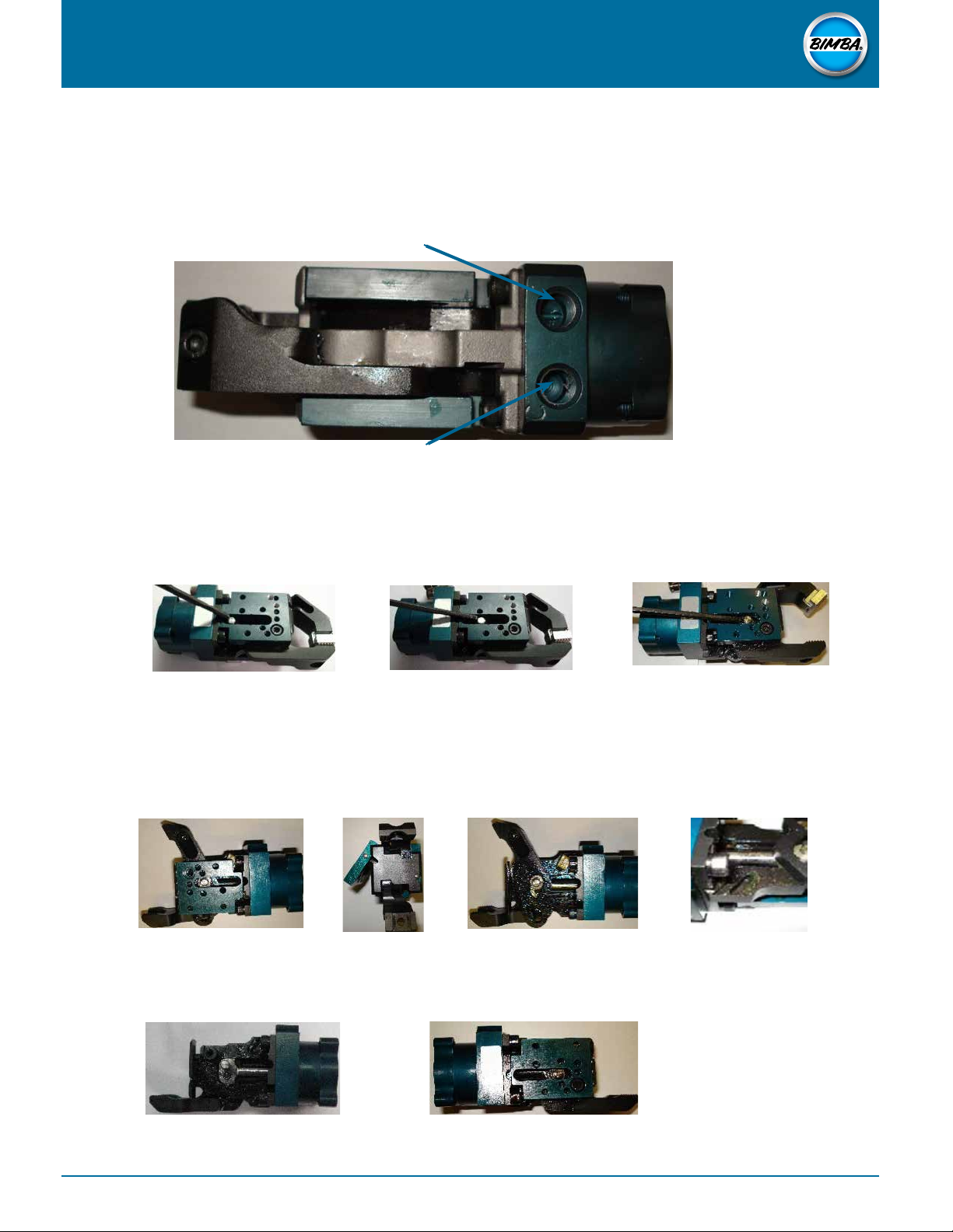
1) Verify that jaws shall open freely. Look for any irregular movement, binding, or interference.
SPECIFICATIONS
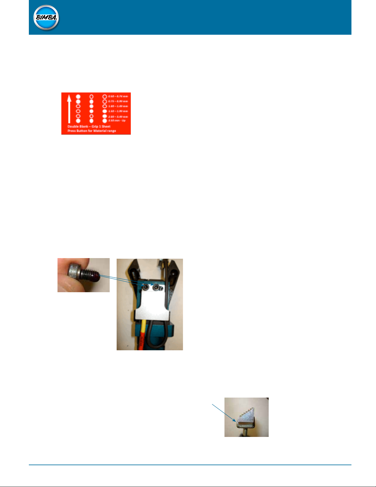
3. Apply Red Loctite 262 or equivalent to sensor stud, place thru jaw and tighten sensor nut to 72in-lb.
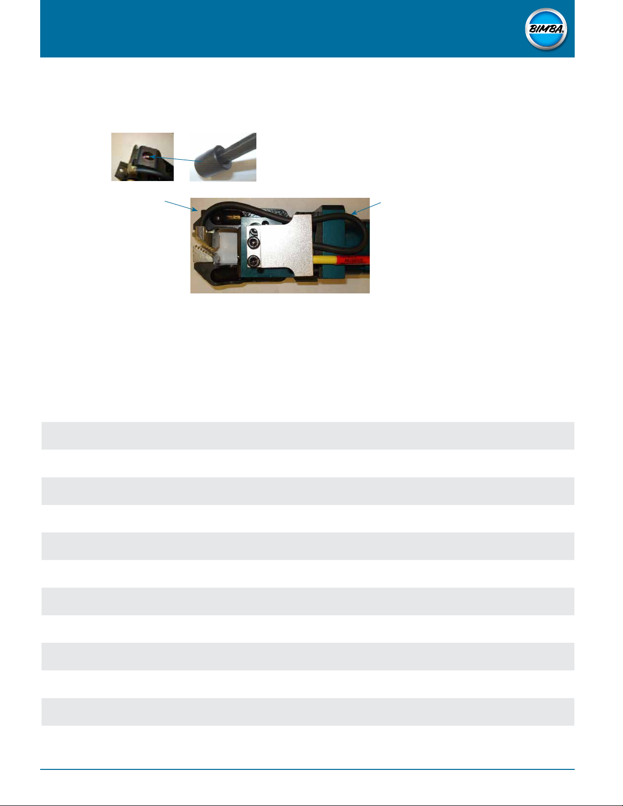
Cable should follow
the contour of the
gripper jaw
Cable storage loop
can be adjusted with
a push/pull motion to
provide more or less
cable slack in gripper
jaw area

BPGS PNEUMATIC GRIPPER SYSTEM
User Manual
BIM-BPGSM-0519 Rev 1 | For Technical Assistance: 800-442-4622
11
Chisel jaw / shovel Regular / flange jaw
Single blank
thickness
Movable jaw
pad color
Opposing fixed
jaw color
Moveable jaw
pad color
Opposing jaw
pad color
0.50mm to 2.0mm Black (note 1) Black Black Black
2.01mm to 3.5mm Silver Black Silver Silver
3.51mm to 5.0mm Black (note 1) Silver Gold Silver
5.01mm to 6.5mm Silver Silver n/a n/a
6.51mm to 8.0mm Black (note 1) Gold n/a n/a
8.01mm to 9.5mm Silver Gold n/a n/a
Note: A shim is required under a black pad when it is installed on a chisel jaw gripper. This shim is included in all black replacement pad kits for the chisel jaw gripper.

BPGS PNEUMATIC GRIPPER SYSTEM
User Manual
BIM-BPGSM-0519 Rev 1 | For Technical Assistance: 800-442-4622
12
TECHNICAL DOCUMENTS
Visit the Bimba website for additional models, drawings, and further documentation.
www.bimba.com
SUPPLIER CONTACT
To purchase electric motion products, accessories, or receive further information,
contact your local Bimba distributor or contact Bimba directly.
Bimba Manufacturing Headquarters
25150 S Governors Hwy University Park, Illinois 60484
Phone: 708-534-8544
Toll Free: 800-44-BIMBA
Fax: 708-235-2014
www.bimba.com
© Copyright 2019 Bimba Manufacturing Company. All Rights Reserved. HM-BIM-BPGSM-0519 Eective May 2019.
This manual suits for next models
13
Table of contents
Other IMI Industrial Equipment manuals
Popular Industrial Equipment manuals by other brands

Index
Index R200 Operating instructions and Maintenance instructions

SABROE
SABROE HPC 100 Mk 4 LL operating manual

OLAER
OLAER IHV Series Repair instructions

Hitachi
Hitachi KPI-252-2002E4E Installation and operation manual

GSi
GSi EVO-50 Construction manual

Spirax Sarco
Spirax Sarco UTD30 Series Installation and maintenance instructions