KIT VALVOLA DI NON RITORNO
SUI FUMI CENTROTHERM
COD. 3.031599
Code. 1.045341 - Rev. ST.005280/001
IT IE
NONRETURN VALVE KIT
ON CENTROTHERM FLUE
CODE 3.031599
AVVERTENZE GENERALI.
Tutti i prodotti Immergas sono protetti con idoneo imballaggio da trasporto.
Il materiale deve essere immagazzinato in ambienti asciutti ed al riparo dalle
intemperie.
Il presente foglio istruzioni contiene informazioni tecniche relative all’installazione
del kit Immergas. Per quanto concerne le altre tematiche correlate all’installazione
del kit stesso (a titolo esemplicativo: sicurezza sui luoghi di lavoro, salvaguardia
dell’ambiente, prevenzioni degli infortuni), è necessario rispettare i dettami della
normativa vigente ed i principi della buona tecnica.
L’installazione o il montaggio improprio dell’apparecchio e/o dei componenti,
accessori, kit e dispositivi Immergas potrebbe dare luogo a problematiche non
prevedibili a priori nei confronti di persone, animali, cose. Leggere attentamente
le istruzioni a corredo del prodotto per una corretta installazione dello stesso.
L'installazione e la manutenzione devono essere eettuate in ottemperanza alle
normative vigenti, secondo le istruzioni del costruttore e da parte di personale
abilitato nonché professionalmente qualicato, intendendo per tale quello avente
specica competenza tecnica nel settore degli impianti, come previsto dalla Legge.
ATTENZIONE.
Il kit deve essere utilizzato solo in abbinamento a caldaie a gas a condensazione
IMMERGAS, in conformità alle istruzioni riportate sul manuale d'installazione
a corredo dell'apparecchio.
Il kit è installabile solamente con fumisteria concentrica 80/125 o con fumi-
steria sdoppiata 80/80, nelle configurazioni che prevedono l'innesto in canna
fumaria collettiva (C10) - (C12).
Questo kit deve essere necessariamente abbinato a fumisteria originale Im-
mergas (Omologata).
COMPOSIZIONE SISTEMA.
Il presente kit per essere funzionale e completo deve essere abbinato ad uno dei
seguenti componenti venduti a parte:
- Kit intubamento C9 adattatore Ø125
- Kit separatore Ø 80 per caldaie a condensazione
GENERAL WARNINGS.
All Immergas products are protected with suitable transport packaging.
e material must be stored in a dry place protected from the weather.
is instruction manual provides technical information for installing the Immergas
kit. As for the other issues related to kit installation (e.g. safety in the workplace,
environmental protection, accident prevention), it is necessary to comply with
the provisions specied in the regulations in force and with the principles of good
practice.
Improper installation or assembly of the Immergas appliance and/or components,
accessories, kits and devices can cause unexpected problems for people, animals
and objects. Read the instructions provided with the product carefully to ensure
proper installation.
Installation and maintenance must be performed in compliance with the regula-
tions in force, according to the manufacturer's instructions and by professionally
qualied sta, meaning sta with specic technical skills in the plant sector, as
envisioned by the law.
1
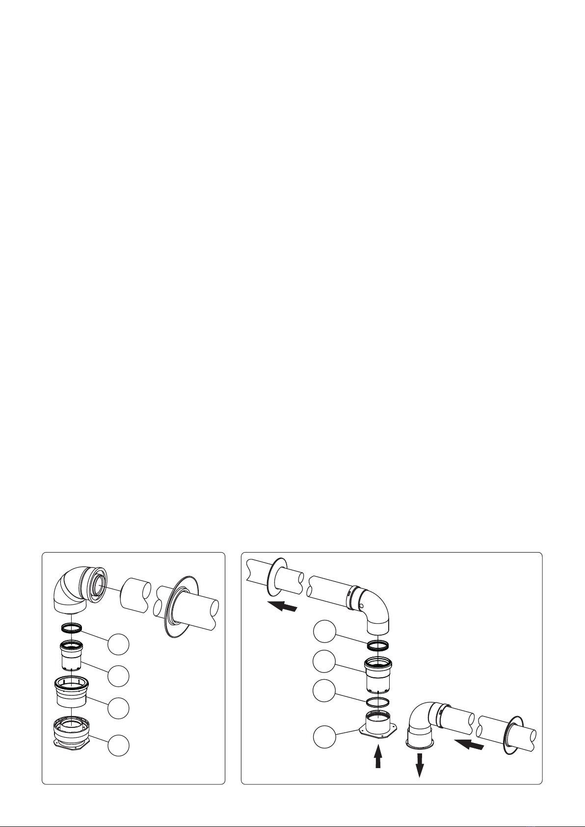
Il Kit comprende:
N° 1 - Guarnizione Ø80 (1)
N° 1 - Valvola di non ritorno sui fumi Ø80 (2)
N° 1 - Prolunga Ø125 (3)
N° 1 - Distanziale Ø80 sp. 5 mm (4)
N° 1 - Adesivo informativo in lingua (da applicare sulla facciata mantello)
e kit comprises:
N° 1 - Lip seal Ø80 (1)
N° 1 - Non-return valve on ue Ø80 (2)
N° 1 - Extension Ø125 (3)
N° 1 - Spacer Ø80 sp. 5 mm (4)
N° 1 - Information sticker in the language (to be applied on the front casing)
ATTENTION.
e kit must be used only in conjunction with IMMERGAS gas condensing
boilers, in accordance with the instructions given in the installation manual
supplied with the appliance.
e kit can be installed only with concentric ue ø80/125 or with split ue
ø80/80, in the congurations that require the connection in the collective ue
(C10) - (C12).
is kit must necessarily be combined with the original Immergas ue system
(Homologated).
SYSTEM COMPOSITION.
This kit must be combined with one of the following components (sold
separately) to be functional and complete:
- C9 Ducting kit Ø 125 adapter
- Separator kit Ø 80 for condensing boilers