Immergas VICTRIX 50-75-90-115 User manual

Montaggio Kit.
Premontare il gruppo tre vie in ottone (4) con il motorino (5),
in modo che il lato morsettiera dello stesso sia posizionato verso
il lato "A" stampato sul corpo tre vie in ottone (4), accessibile
comunque dalla parte anteriore della caldaia.
Montare il tubo (6) alla valvola miscelatrice (lato A) interponendo
la relativa guarnizione senza serrare a fondo il dado.
Montare la valvola (4) con tubo (6) al collettore (3) interponendo
le relative guarnizioni senza serrare a fondo i dadi.
Al termine serrare a fondo tutti i dadi di collegamento.
Collegare il kit 3 vie per abbinamento unità bollitore come da
gura 2 assicurandosi di interporre le guarnizioni (1).
KIT VALVOLA TRE VIE PER ABBINAMENTO
UNITÀ BOLLITORE VICTRIX 50-75-90-115
COD. 3.015223
Legenda:
1 - Guarnizione
2 - Tronchetto di mandata all'unità bollitore
3 - Collettore 3 vie
4 - Valvola 3 vie in ottone
5 - Motore azionamento valvola
6 - Tubo di raccordo
G1" 4
1
5
6
G1"1/2
G1"1/2
1
G1"1/2
G1"
2
A
B
AB
G1" G1"
G1"
3
VICTRIX 50-75-90-115 3-WAY VALVE KIT FOR
COUPLING WITH GENERATOR UNIT
CODE 3.015223
Key:
1 - Seal
2 - Delivery section to generator unit
3 - 3-way valve mainfold
4 - Brass 3-way valve
5 - Valve operation motor
6 - Connection pipe
Kit assembly.
Preassemble the brass 3-way unit (4) with motor (5), so that its
terminal block side is positioned towards side “A” stamped on
brass 3-way body (4), and in any case accessible from the front
of the boiler.
Fit pipe (6) on the mixer valve (side A), interposing the relevant
seal without tightening down the nut.
Fit the valve (4) with pipe (6) on mainfold (3), interposing the
relative seals without tightening down the nuts.
On completion, tighten down all the connection nuts.
Connect the 3-way kit for coupling with generator unit as shown
in g. 2, making sure to interpose the seals (1).
Fig. 1
Fig. 2

Allacciamento elettrico.
N:B: nel caso di utilizzo dell’unità bollitore Immergas, è necessario
sostituire la sonda boiler già montata sull’unità bollitore con la
sonda boiler presente all’interno del kit valvola 3 vie.
Collegare la sonda boiler (B2) presente nel kit sui morsetti R e H
della morsettiera assicurandosi di aver precedentemente asportato
il ponticello (R8).
Collegare i cavi provenienti dal motore comando valvola a tre vie
(M30) come descritto nella gura sotto riportata.
Collegare il connettore (3) al morsetto (T) utilizzando il cavo nero
fornito in dotazione.
Collegare il connettore (6) al morsetto (S) utilizzando il cavo
arancio fornito in dotazione.
Collegare il connettore (2) al morsetto (K) utilizzando il cavo
rosso fornito in dotazione.
Attenzione: La caldaia ha un grado di isolamento elettrico IPX5D
e può essere installata anche all'esterno senza bisogno di prote-
zioni aggiuntive, è opportuno comunque se installati all'esterno
coibentare le tubazioni e proteggere dagli agenti atmosferici il kit
in base al suo grado di protezione elettrica.
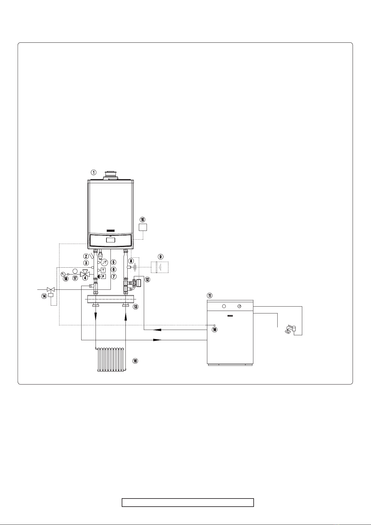
MANDATA
BOILER
RITORNO
BOILER
BOILER
DELIVERY
BOILER
RETURN
Electrical connection.
N.B.: if the Immergas generator unit is used, the boiler sensor
already tted on the generator unit must be replaced with boiler
sensor included in the 3-way valve kit.
Connect boiler sensor (B2), included in the kit, to terminals R
and H on the terminal board, making sure to previously remove
the jumper (R8).
Connect the cables coming from the 3-way valve control motor
(M30) as described in the gure below.
Connect connector (3) to terminal (T) using the black cable
supplied.
Connect connector (6) to terminal (S) using the orange cable
supplied.
Connect connector (2) to terminal (K) using the red cable sup-
plied.
Important: e boiler has IPX5D electrical insulation rating
and can also be installed outside, without requiring additional
protection; however, if installed outside it is advisable to insulate
the piping and protect the kit from atmospheric agents according
to its electrical protection rating.
Sonda boiler
Boiler sensor
Valvola tre vie
3-way valve
Fig. 3
Fig. 4

Parametri modicabili.
Para-
metro descrizione
Valore
limite
inferiore
Valore
limite
superiore
Valore di
fabbrica
1
Valore di set
acqua calda
sanitaria
20 °C 70 °C 20 °C
2
Modalità
di funzio-
namento
sanitario
0 = escluso
1 = attivo
2 = escluso + pompa
continua
3 = attivo + pompa conti-
nua
0
3
Modalità
di funzio-
namento
riscalda-
mento
0 = escluso
1 = attivo
2 = escluso + pompa
continua
3 = attivo + pompa conti-
nua
1
4
Temperatu-
ra massima
di mandata
riscalda-
mento
20 °C 90 °C 85 °C
La caldaia esce di fabbrica impostata come solo riscaldamento, nel
caso in cui si installi un unità bollitore esterno occorre modicare
le impostazioni della scheda di caldaia nel seguente modo:
- premere il tasto MODE una volta per accedere alla modalità
parametri (PARA)
- per mezzo del tasto STEP scegliere il parametro da modicare
(parametro 1)
- cambiare il valore agendo sui tasti + o -
- premere il tasto STORE per memorizzare il nuovo valore
- per mezzo del tasto STEP scegliere il parametro da modicare
(parametro 2)
- cambiare il valore agendo sui tasti + o - (impostandolo su 1)
- premere il tasto STORE per memorizzare il nuovo valore
Per eventuali regolazione della potenza in sanitario vedere indi-
cazioni sul libretto di caldaia.
Modiable parameters.
Param-
eter description Lower limit
value
Upper limit
value
Factory
value
1
Domestic
hot water
setting value
20 °C 70 °C 20 °C
2
Domestic
hot water
function
mode
0 = cut out
1 = active
2 = cut out + continuous
pump
3 = active + continuous
pump
0
3
Heating
function
mode
0 = cut out
1 = active
2 = cut out + continuous
pump
3 = active + continuous
pump
1
4
Max. heat-
ing delivery
temperature 20 °C 90 °C 85 °C
B oilers leave the factory set for heating only; to install an external
generator unit the boiler card settings must be modied as follows:
- press the MODE key once to enter parameter mode (PARA)
- using the STEP key select the parameter to be changed (param-
eter 1)
- use the + or - keys to change the value
- press the STORE key to store the new value
- using the STEP key select the parameter to be changed (param-
eter 2)
- use the + or - keys to change the value (setting it to 1)
- press the STORE key to store the new value
For any adjustment of output in domestic hot water see instruc-
tions in the boiler manual.

COD. 1.020128 REV. 15.015747/004
Esempio installativo caldaia singola con kit valvola tre vie.
Legenda:
1 - Generatore
2 - Pozzetto portatermometro
3 - Sonda per bulbo valvola intercettazione combustibile
4 - Rubinetto portamanometro omologato ISPESL
5 - Termometro omologato ISPESL
6 - Termostato riarmo manuale omologato ISPESL
7 - Pressostato riarmo manuale omologato ISPESL
8 - Attacco per vaso espansione
9 - Vaso espansione
10 - Sonda temperatura bollitore
11 - Unità bollitore esterna
12 - Valvola 3 vie collegamento boiler
13 - Disgiuntore idraulico
14 - Valvola intercettazione combustibile
15 - Sonda esterna
16 - Impianto a radiatori
17 - Riccio ammortizzatore
18 - Manometro omologato ISPESL
Installation example of single boiler with 3-way valve kit.
Key:
1 - Generator
2 - ermometer well
3 - Sensor for gas on/o valve bulb
4 - Manometer cock
5 - ermometer
6 - Manual reset thermostat
7 - Manual reset pressure switch
8 - Connection for expansion tank
9 - Expansion tank
10 - Generator temperature sensor
11 - External generator unit
12 - Boiler connection 3-way valve
13 - Hydraulic disjunctor
14 - Gas on/o valve
15 - External sensor
16 - Radiator system
17 - Water hammer reducing loop
18 - Manometer
Fig. 5
Other Immergas Control Unit manuals
Popular Control Unit manuals by other brands

VAT
VAT 244 Series Installation, operating, & maintenance instructions

Nibe
Nibe SAM 40 user manual

Aerotech
Aerotech ARMS Series Hardware manual

CSQ
CSQ VL10 Series Installation, operation and maintenance instructions

Glowworm
Glowworm SYSTEMPRO Installation and servicing

Siemens
Siemens SIWAREX FTC Device manual