8
THIS SHEET MUST BE LEFT WITH THE USER ALONG WITH THE INSTRUCTIONS MANUAL FOR THE FINISHED PRODUCT
IE
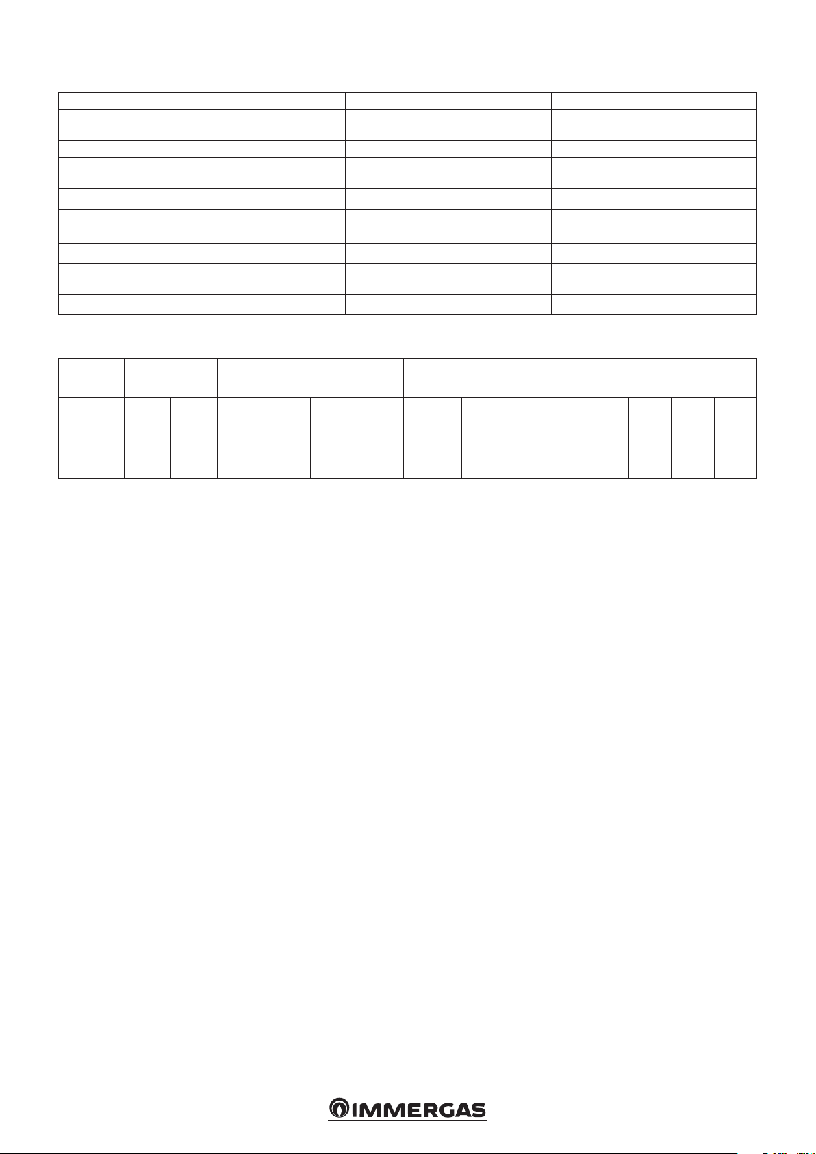
(*) ATTENTION.
e 5 support feet are adjustable.
e height of the feet ranges from 35 to 50 mm.
Domus Container Value:
height with pack feet: 2095 mm
maximum reachable height: 2110 mm
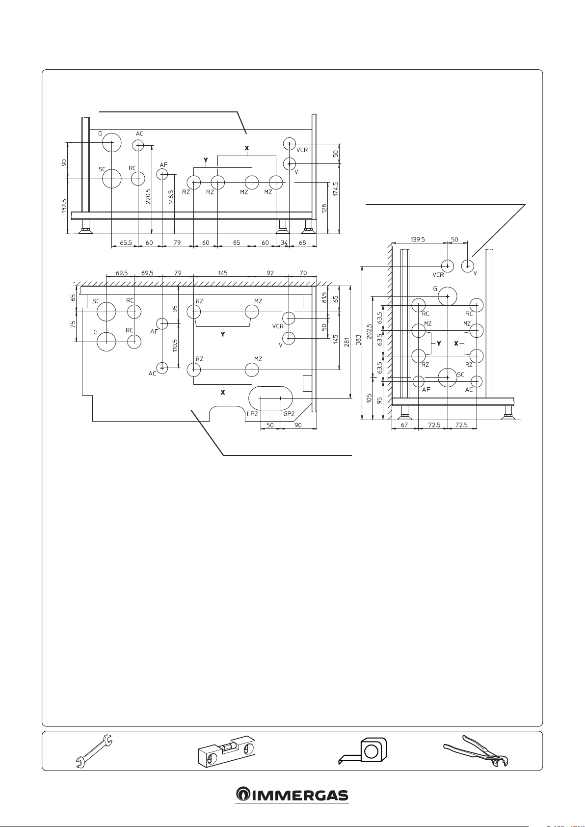
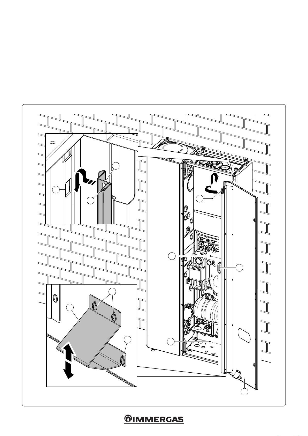
ATTENTION: the connections to the heat pump
in Trio Pack can only be made from below, as
indicated in the connection template (Fig. 2); the
connections to the heat pump in the remaining
installations can only be made on the rear side.
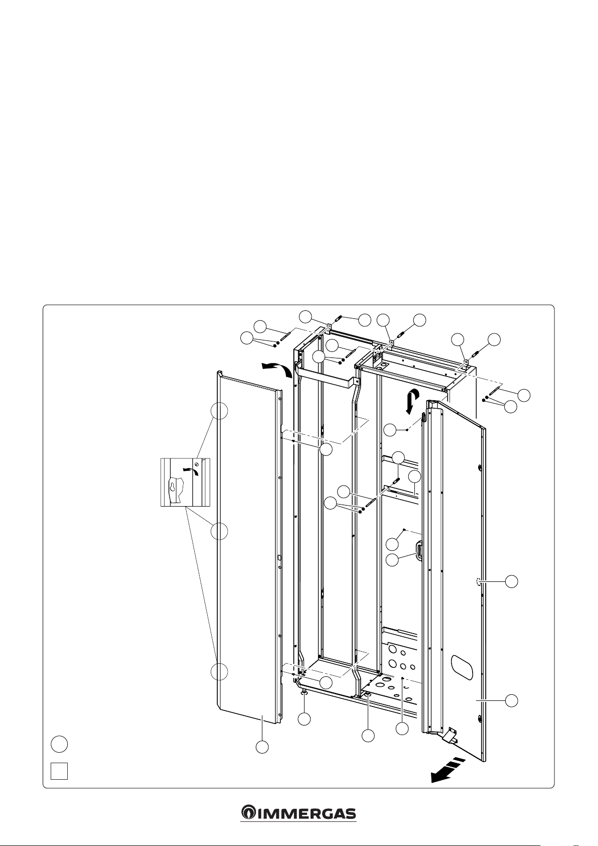
ATTENTION: in case of installation with con-
centric flue system, it is necessary to use the
anged stub pipe kit to exit the Domus Container
clearance
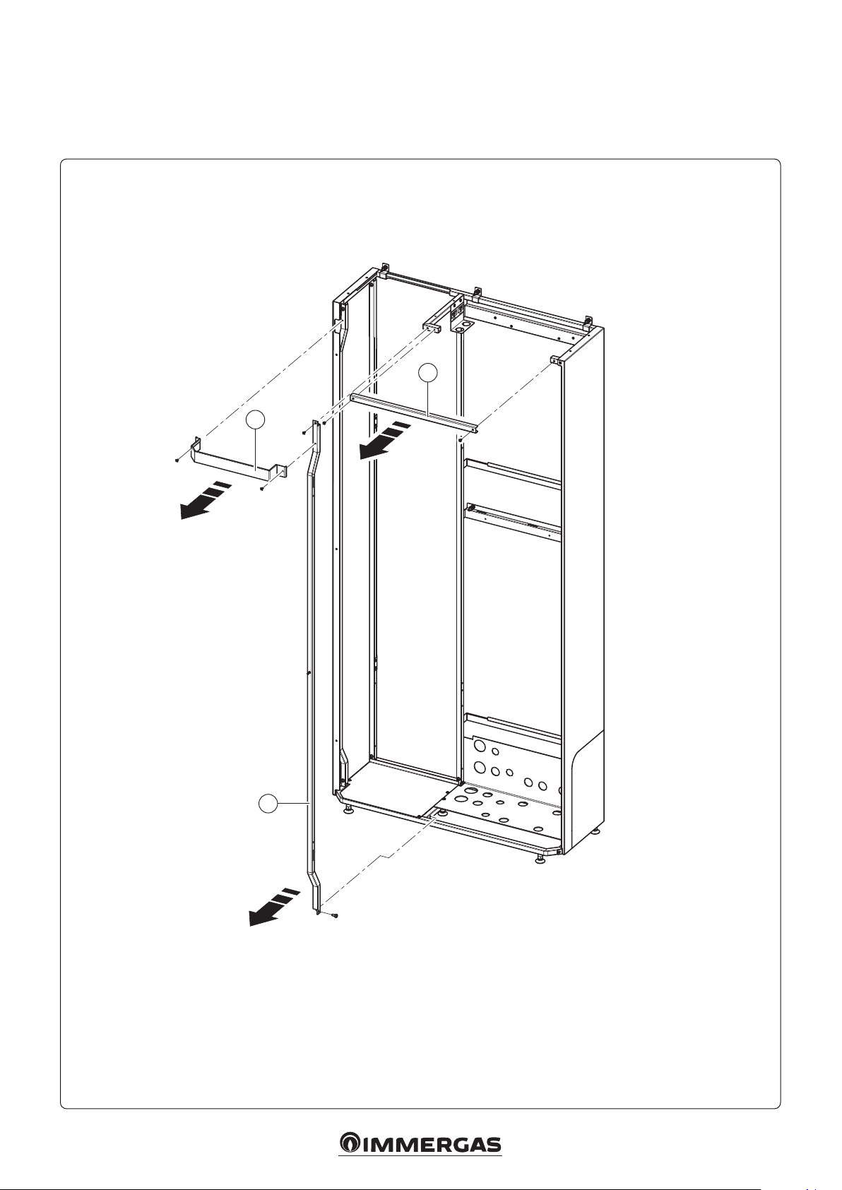
N.B.: the Domus Container comes with 3 mobile
points for wall mounting at the top; place them
as needed, without them interfering with the
products installed inside it.
Right-hand side minimum size to open
and disassemble door
Maximum door opening
- not indispensable -
MAIN DIMENSIONS.
Fig. 1
GENERAL WARNINGS.
All Immergas products are protected with suitable transport packaging.
e material must be stored in a dry place protected from the weather.
is instruction manual provides technical information for installing
the Immergas kit. As for the other issues related to kit installation (e.g.
safety at the workplace, environmental protection, accident prevention),
it is necessary to comply with the provisions specied in the regulations
in force and with the principles of good practice.
Improper installation or assembly of the Immergas appliance and/or
components, accessories, kits and devices can cause unexpected problems
for people, animals and objects. Read the instructions provided with the
product carefully to ensure proper installation.
Installation and maintenance must be performed in compliance with the
regulations in force, according to the manufacturer's instructions and by
professionally qualied sta, meaning sta with specic technical skills
in the plant sector, as envisioned by the law.
DET. A
SCALE 2:1
DET. B
SCALE 2:1