Immergas Hercules Condensing 26 2 E User manual

HERCULES
Condensing 26 2 E / 32 2 I
Ecological floor-standing
condensing boiler
with stainless steel storage tank
HERCULES Condensing 26 2 E / 32 2 I


1
STHCkW ed 04/09 HERCULES Condensing Export
Technical Documentation Technical Documentation
HERCULES Condensing
Ecological oor-standing condensing
boiler with 120 litre storage tank
HERCULES Condensing 26 2 E
HERCULES Condensing 32 2 I
HERCULES Condensing ABT 32 2 I
HERCULES Condensing combines the advantages of an
ecological condensing boiler with VICTRIX Superior type mi-
croprocessor with those of a oor standing boiler with storage
tank. e range envisions two versions with useful heat outputs
of 23.9 kW (20554 kcal/h) and 32.0 kW (27520 kcal/h). Both
models are equipped with a total premix combustion system,
which guarantees particularly low pollutant emissions and
allows functioning with methane or LPG. anks to condensa-
tion technology, it is characterised for its high eciency and
for the large modulating eld (20÷100% of the nominal heat
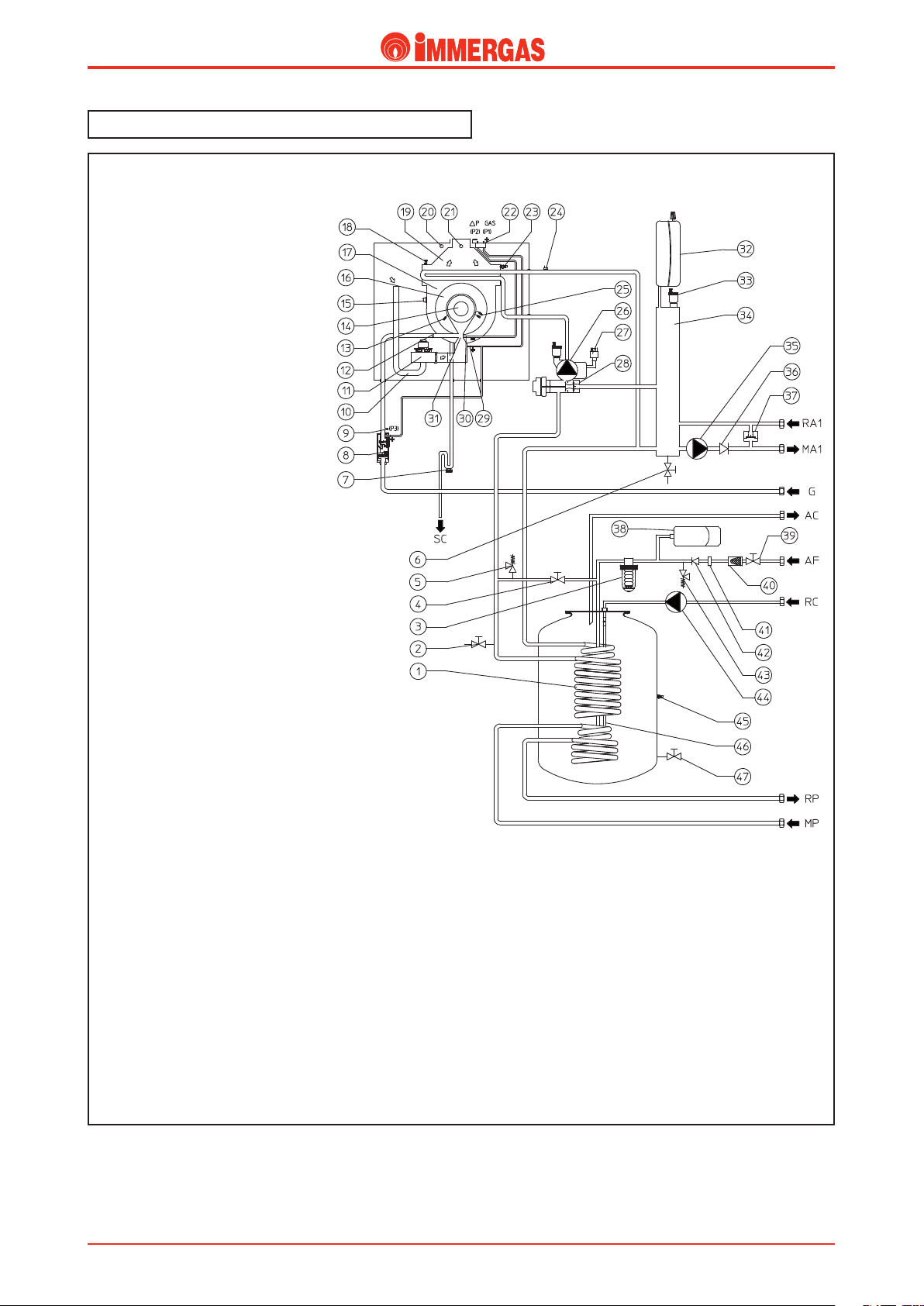
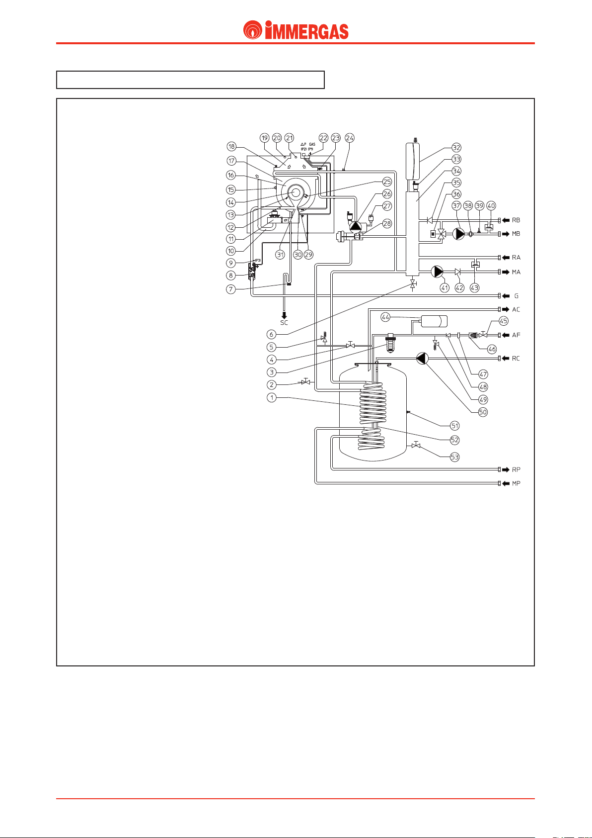
output). e hydraulic circuit, made up from one stainless steel
water-gas coil exchanger, a hydraulic manifold inserted as per
standard and two pumps, means that the boiler is suitable for
the heating systems that require high ow rate.
HERCULES Condensing can function in zone systems con-
trolled by pumps: it is, in fact, prepared to house the pumps
necessary to control up to 3 zones on the heating system inside
the casing. It is also prepared for the realisation of mixed sys-
tems: one high temperature zone (e.g. radiators) and two low
temperature zones (e.g. oor radiating panels) by inserting the
optional kit inside the casing (including pumps, mixer valves
and zone management board). e new zone management board
allows to use the Remote Control (optional) to control that
considered to be the main zone.
N.B.: e HERCULES Condensing ABT boiler is equipped
to manage a high temperature zone (example radiators) and a
low temperature zone (example oor radiating panels). e tem-
perature of the ow water onto the low temperature zones can
be adjusted on the boiler control panel (whenever functioning
General features.
with variable temperature is not envisioned) from 25 to 50°C.
All models are prepared for coupling and connection of the
storage tank to solar panel systems (optional).
e new electronics allow the connection of the appliance
to the Comando Amico Remoto and to the Super Comando
Amico Remoto remote control; both allow to manage and
control the boiler at a distance with great ease. Using the Super
CAR it is possible to indierently vary some settings from the
boiler control panel and from the Super CAR control panel,
such as: selection of Summer Winter, DHW set point, DHW
comfort status, Reset.
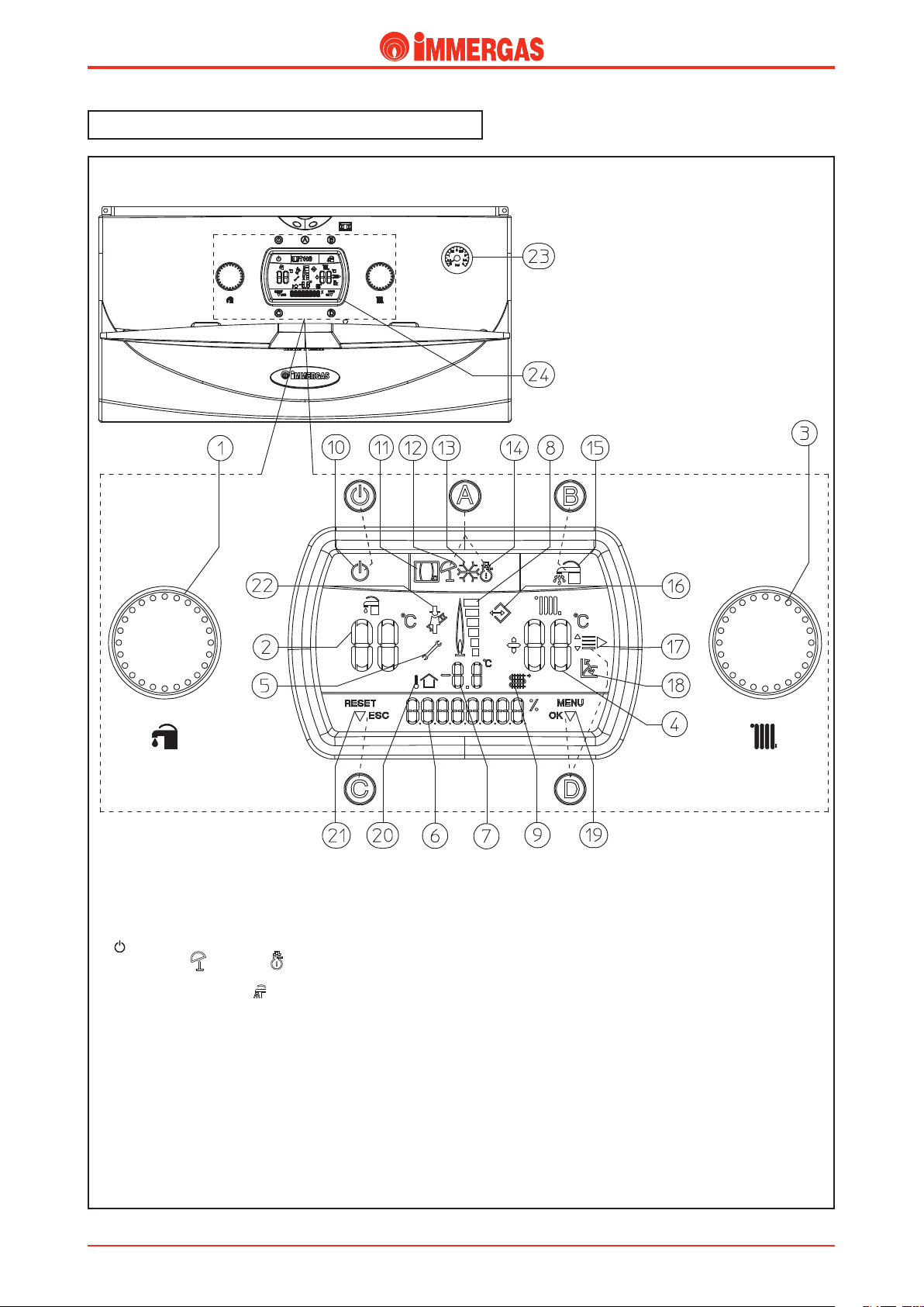
e adjustment and the control of the appliance are entrusted
to a P.C.B. with continuous ame modulation. e boiler
functioning parameters are set using the buttons and knobs
while display of the status, functioning mode and anomalies
takes place on the back-lit digital display.
e DHW circuit is equipped with a 5 litre expansion vessel
and a120 litre stainless steel storage tank which, as well as the
advantages of storage, guarantees the instantaneous produc-
tion of hot water.
HERCULES Condensing must be installed using the intake/
exhaust kits or the ducting systems (Ø 60 mm rigid, Ø 80 mm
rigid and Ø 80 mm exible) realised in plastic and designed
expressly for Immergas condensing boilers.

2
STHCkW ed 0409 HERCULES Condensing Export
Technical DocumentationTechnical Documentation
Main dimensions and connections.
HERCULES Condensing
HERCULES Condensing ABT
Key:
RA3 - Zone 3 high temperature system return G
3/4” (optional)
MA3 - Zone 3 high temperature system ow G 3/4”
(optional)
RA2 - Zone 2 high temperature system return G
3/4” (optional)
MA2 - Zone 2 high temperature system ow G 3/4”
(optional)
RB2 - Zone 2 low temperature system return G 1”
(optional)
MB2 - Zone 2 low temperature system ow G 1”
(optional)
RB1 - Zone 1 low temperature system return G 1”
(optional)
MB1 - Zone 1 low temperature system ow G 1”
(optional)
RA1 - Zone 1 high temperature system return G
3/4”
MA1 - Zone 1 high temperature system ow G 3/4”
G - Gas supply G 1/2”
AC - DHW outlet G 3/4”
AF - DHW inlet G 3/4”
RC - Recirculation G 1/2” (optional)
RP - Solar panels return G 3/4” (optional)
MP - Solar panels ow G 3/4” (optional)
SC - Condensate drain
(minimum internal diameter Ø 13 mm)
Key:
RB2 - Zone 2 low temperature system return G 1”
(optional)
MB2 - Zone 2 low temperature system ow G 1”
(optional)
RB1 - Zone 1 low temperature system return G 1”
MB1 - Zone 1 low temperature system ow G 1”
RA1 - Zone 1 high temperature system return G
3/4”
MA1 - Zone 1 high temperature system ow G 3/4”
G - Gas supply G 1/2”
AC - DHW outlet G 3/4”
AF - DHW inlet G 3/4”
RC - Recirculation G 1/2” (optional)
RP - Solar panels return G 3/4” (optional)
MP - Solar panels ow G 3/4” (optional)
SC - Condensate drain
(minimum internal diameter Ø 13 mm)

3
STHCkW ed 04/09 HERCULES Condensing Export
Technical Documentation Technical Documentation
HERCULES Condensing control panel.
Key:
- Stand-by - On Button
A- Summer ( ) and winter ( ) functioning mode selection but-
ton
B- DHW priority button ( )
C- (RESET) / menu exit (ESC) reset button
D- Menu entry button (MENU)/ data conrmation (OK)
1 - Domestic hot water temperature selector
2 - Domestic hot water temperature set
3 - Central heating temperature selector
4 - Central heating temperature set
4 - Presence of anomalies
6 - Display of boiler functioning status
8 - Flame presence symbol and relative power scale
9 and 7 - Primary heat exchanger outlet water temperature
10 - Boiler in Stand-by
11 - Boiler connected to remote control (Optional)
12 - Functioning in summer mode
13 - Anti-freeze function in progress
14 - Functioning in winter mode
15 - Functioning with domestic hot water priority active
16 - Connection to external tools for technician
17 - Display of menu items
18 - Functioning with external temperature probe active
19 - Display of data conrmation or menu access
20 and 7 - External temperature display
with external probe connected (optional)
21 - Display of reset or exit menu request
22 - Chimney sweep function in progress
23 - Boiler manometer
24 - Multi-function display

4
STHCkW ed 0409 HERCULES Condensing Export
Technical DocumentationTechnical Documentation
HERCULES Condensing main components.
Key:
1 - Stainless steel storage tank unit
2 - DHW recirculation pump (optional)
3 - ree-way valve (motorised)
4 - Zone 1 by-pass
5 - Zone 1 one-way valve
6 - Zone 1 pump
7 - Safety thermostat (Low temperature) (optional)
8 - Flow probe (Low temperature) (optional)
9 - Zone 2 pump (optional)
10 - Zone 2 one-way valve (optional)
11 - Zone 2 by-pass (optional)
12 - Mixing valve (optional)
13 - Condensation module
14 - Flue safety thermostat
15 - Burner
16 - Ignition electrode
17 - Detection electrode
18 - Venturi
19 - Gas nozzle
20 - Fan
21 - Cold water inlet valve
22 - 8 bar safety valve
23 - Air intake pipe
24 - 3 bar safety valve
25 - D.H.W. expansion vessel
26 - System lling valve
27 - Condensate drain trap
28 - Polyphosphate dispenser (optional)
29 - Domestic hot water probe
30 - Storage tank unit draining valve
31 - Sample points (air A) - (ue gas F)
32 - Positive signal pressure point
33 - Negative signal pressure point
34 - Manual air vent valve
35 - Vent valve
36 - Zones management electrical connection box (optional)
37 - Hydraulic manifold
38 - System expansion vessel
39 - Flow probe
40 - Safety thermostat
41 - Manifold draining valve
42 - System pressure switch (absolute)
43 - Boiler Pump
44 - Sealed Chamber
45 - Gas valve
46 - System draining valve

5
STHCkW ed 04/09 HERCULES Condensing Export
Technical Documentation Technical Documentation
HERCULES Condensing ABT main components.
Key:
1 - Stainless steel storage tank unit
2 - DHW recirculation pump (optional)
3 - ree-way valve (motorised)
4 - High temp. zone automatic by-pass
5 - High temp. zone one-way valve
6 - High temperature zone system pump
7 - Low temperature safety thermostat
8 - Low temp. ow probe
9 - Low temperature zone system pump
10 - Low temp. zone one-way valve
11 - Low temp. zone automatic by-pass
12 - Mixing valve
13 - Condensation module
14 - Flue safety thermostat
15 - Burner
16 - Ignition electrode
17 - Detection electrode
18 - Venturi
19 - Gas nozzle
20 - Fan
21 - Cold water inlet valve
22 - 8 bar safety valve
23 - Air intake pipe
24 - 3 bar safety valve
25 - D.H.W. expansion vessel
26 - System lling valve
27 - Condensate drain trap
28 - Polyphosphate dispenser (optional)
29 - Domestic hot water probe
30 - Storage tank unit draining valve
31 - Sample points (air A) - (ue gas F)
32 - Positive signal pressure point
33 - Negative signal pressure point
34 - Manual air vent valve
35 - Vent valve
36 - Zones management electrical connection box
37 - Hydraulic manifold
38 - System expansion vessel
39 - Flow probe
40 - Safety thermostat
41 - Manifold draining valve
42 - System pressure switch (absolute)
43 - Boiler Pump
44 - Sealed Chamber
45 - Gas valve
46 - System draining valve

6
STHCkW ed 0409 HERCULES Condensing Export
Technical DocumentationTechnical Documentation
HERCULES Condensing hydraulic diagram.
Key:
1 - Stainless steel coil for storage tank
2 - System draining valve
3 - Polyphosphate dispenser (optional)
4 - System lling valve
5 - 3 bar safety valve
6 - Manifold draining valve
7 - Condensate drain trap
8 - Gas valve
9 - Gas valve outlet pressure point (P3)
10 - Air intake pipe
11 - Fan
12 - Gas nozzle
13 - Detection electrode
14 - Burner
15 - Flue safety thermostat
16 - Condensation module covers
17 - Condensation module
18 - Manual air vent valve
19 - Flue hood
20 - Air sample point
21 - Flue sample point
22 - Pressure point ΔP gas
23 - Flow probe
24 - Safety thermostat
25 - Ignition electrode
26 - Boiler Pump
27 - System pressure switch (absolute)
28 - ree-way valve (motorised)
29 - Venturi positive sign P1
23 - Venturi negative sign P2
31 - Air/gas Venturi manifold
32 - System expansion vessel
33 - Vent valve
34 - Hydraulic manifold
35 - Zone 1 pump
36 - Zone 1 one-way valve
37 - Zone 1 by-pass
38 - D.H.W. expansion vessel
39 - Cold water inlet valve
40 - Cold water inlet lter
41 - Flow limiter
42 - Cold water inlet non-return valve
43 - 8 bar safety valve
44 - DHW recirculation pump (optional)
45 - Domestic hot water probe
46 - Magnesium anode
47 - Storage tank unit draining valve
RA1 - Zone 1 system return (High temperature)
MA1 - Zone 1 system ow (High temperature)
G - Gas supply
AC - Domestic hot water outlet
AF - Domestic cold water inlet
RC - Domestic hot water recirculation
RP - Return from solar panels
MP - Flow from solar panels
e hot water used for central heating and domestic hot water
is produced via a primary and a secondary circuit (DHW)
which are aected according to necessity.
Standard Conguration

7
STHCkW ed 04/09 HERCULES Condensing Export
Technical Documentation Technical Documentation
HERCULES Condensing ABT hydraulic diagram.
Key:
1 - Stainless steel coil for storage tank
2 - System draining valve
3 - Polyphosphate dispenser (optional)
4 - System lling valve
5 - 3 bar safety valve
6 - Manifold draining valve
7 - Condensate drain trap
8 - Gas valve
9 - Gas valve outlet pressure point (P3)
10 - Air intake pipe
11 - Fan
12 - Gas nozzle
13 - Detection electrode
14 - Burner
15 - Flue safety thermostat
16 - Condensation module covers
17 - Condensation module
18 - Manual air vent valve
19 - Flue hood
20 - Air sample point
21 - Flue sample point
22 - Pressure point ΔP gas
23 - Flow probe
24 - Safety thermostat
25 - Ignition electrode
26 - Boiler Pump
27 - System pressure switch (absolute)
28 - ree-way valve (motorised)
29 - Venturi positive sign P1
23 - Venturi negative sign P2
31 - Air/gas Venturi manifold
32 - System expansion vessel
33 - Vent valve
34 - Hydraulic manifold
35 - Low temp. zone one-way valve
36 - Low temp. zone mixing valve
37 - Low temperature zone system pump
38 - Low temperature safety thermostat
39 - Low temp. zone ow probe
40 - Low temp. zone automatic by-pass
41 - High temperature zone system pump
42 - High temp. zone one-way valve
43 - High temp. zone automatic by-pass
44 - D.H.W. expansion vessel
45 - Cold water inlet cock
46 - Cold water inlet lter
47 - Flow limiter
48 - Cold water inlet non-return valve
49 - 8 bar safety valve
50 - DHW recirculation pump (optional)
51 - Domestic hot water probe
52 - Magnesium anode
53 - Storage tank unit draining valve
RB - Low temperature zone system return
MB - Low temperature zone system ow
RA - High temperature zone system return
MA - High temperature zone system ow
G - Gas supply
AC - Domestic hot water outlet
AF - Domestic hot water inlet
RC - Domestic hot water recirculation
RP - Return from solar panels
MP - Flow from solar panels

8
STHCkW ed 0409 HERCULES Condensing Export
Technical DocumentationTechnical Documentation
Primary circuit (boiler circuit).
e primary circuit, with relative control and safety devices,
is started every time there is a central heating or domestic
hot water request.
Operation (see HERCULES Condensing hy-
draulic diagram).
e heat contained in the combustion products is absorbed
by the pipes of the water-gas primary heat exchanger with coil
inserted in the condensation module (17) which then gives
the heat up to the water made to circulate inside the boiler
pump (26).
e water is introduced directly into the hydraulic manifold
(34) and therefore to the system or can be diverted inside the
storage tank coil (1).
is depends on the position of the motorised 3-way valve
(28), which depending on request, allows ow towards the
system ow and return pipes of the hydraulic manifold (34)
or causes diversion towards the coil (1).
Boiler pump (1).
Operates on the primary circuit return immediately after the
3-way valve to which it is connected. It is part of the integrated
multifunction unit realised in composite material.
ere is a seat on the body where the automatic air vent valve
(2) is housed.
1
2

9
STHCkW ed 04/09 HERCULES Condensing Export
Technical Documentation Technical Documentation
2
1
4
35
Primary heat exchanger
(condensation module).
It is formed by a casing that contains 4 (version 26 2 E) and 5
(version 32 2 I) coil-shaped elements.
Each element is made up from 5 elliptical spirals (3).
e entire module is realised in stainless steel and its internal
part makes up the sealed combustion chamber and the con-
densation chamber (2).
HERCULES Condensing 26 2 E.
e rst three elements are aected directly by the action of
the cylindrical burner applied to the front, while the fourth is
arranged in the condensation chamber, which is separated from
the combustion chamber by sheet steel (see ue circuit).
To reduce head losses to a minimum and increase the ow rate
available to the system, the ow is made up from the parallel
connection of the rst two elements, the return, instead is made
up from the parallel connection of the last two elements.
HERCULES Condensing 32 2 I.
e rst four elements are aected directly by the action of
the cylindrical burner applied to the front, while the fth is
arranged in the condensation chamber, which is separated from
the combustion chamber by sheet steel (see ue circuit).
To reduce head losses to a minimum and increase the ow
rate available to the system, the ow is made up from the
parallel connection of the rst three elements, the return,
instead is made up from the parallel connection of the last
two elements.
For both versions, the heat exchanger inlet is connected to
the pump ow and the outlet, on which the NTC central
heating probe is positioned (1), is connected to the primary
circuit ow.
e primary circuit return and ow pipes are coupled using
threaded ttings with at gasket.
e ue hood (4) is connected to the rear using a relevant
gasket blocked by a metal ring and xed using three nuts to
the steel condensation module.
e condensate drain is also found in the lower part.
To ease the escape of any air bubbles still present in the coils,
there is a manual air vent in the upper part of the module
(5).
FLUE GAS
RETURN
FLOW
CONDENSATE
DRAIN

10
STHCkW ed 0409 HERCULES Condensing Export
Technical DocumentationTechnical Documentation
Motorised 3-way valve.
It is an electric 3-way valve operating on he primary circuit
return that allows, according to request (DHW or CH), to
introduce boiler water into the CH system or the storage
tank coil.
is depends on the position of the shutter (5) which, closes
the passage towards the system opening it at the same time
towards the storage tank (DHW position) or vice versa (CH
position).
e shutter (5) is moved into both positions by powering the
motor (1).
e hydraulic part is made up from a group of composite
material (2) that also integrates the pump and is put into ac-
tion thanks to a motor (1) that causes movement according
to necessity.
Operation.
When it is necessary to reach the CH or DHW position, the
motor (1) is activated by the P.C.B.
Functioning of the motor leads to the movement of the shut-
ter (5) at every 180° rotation and compresses (CH position) or
leaves (DHW position) the shutter contrast spring to release
(4).
Both the spring (4) and the shutter (5) are situated inside the
3-way cartridge (3).
e hydraulic arrival at the requested position, alternatively
causes the opening and closure of one of the two end run micro
switches (6) organised inside the motor box (1).
is allows to remove voltage to the motor blocking it in the
position reached and to enable motor functioning only in the
presence of a dierent request (DHW or CH signal).
PUMP
RETURN
COIL
RETURN
HYDRAULIC
MANIFOLD
RETURN
4
1
2
3
5
Pump
Flow
Storage tank
coil
return
Hydraulic
manifold
return

11
STHCkW ed 04/09 HERCULES Condensing Export
Technical Documentation Technical Documentation
Safety devices and controls.
System lling (3).
It is a ball valve positioned between the boiler circuit and the
domestic cold water inlet that allows to pressurise the CH
system.
e valve is connected to the domestic cold water inlet unit
(4).
System pressure switch (5).
Detects the pressure inside the primary circuit.
Its seat is on the ow pump body directly on the hydraulic unit
and is coupled to a micro switch that prevents functioning of
the burner when the pressure detected is below 0.3 bar.
Prevents overheating of the main heat exchanger.
Automatic air vent valve (6).
Allows the automatic expulsion of the gaseous substances that
may be present in the boiler circuit.
It is mounted on the pump ow directly on the hydraulic
unit.
3 bar safety valve (7).
Prevents the safety pressure in the primary circuit from being
exceeded (3 bar).
It is situated in the right side of the boiler and is visible by
opening the right lateral door. It is positioned on the hydraulic
unit connection pipe - lling valve.
System expansion vessel (8).
It compensates the volume variation consequent to heating
the water, thus limiting the pressure variations.
It has a capacity of 12 litres and a factory-set pressure of 1.0
bar.
It is organised at the rear of the upper right zone of the ap-
pliance.
8
4
3
7
65

12
STHCkW ed 0409 HERCULES Condensing Export
Technical DocumentationTechnical Documentation
GIM Multifunction Integrated Unit.
Before replacing the various components present on the GIM
unit, the water present inside the primary circuit must be
drained by opening the system draining valve positioned on
the storage tank return connection pipe.
Before draining, ensure that the system lling valve is closed.
ree-way valve cartridge replacement (1).
To replace the 3-way cartridge (1) slide the locking clip out (2)
and extract the small electric motor (3) and then unscrew the
screw fasteners (4) that x the cartridge (1) to the composite
body (6).
N.B.: when re-mounting the cartridge, pay particular atten-
tion to correctly insert the two small sheet steel reinforcement
plates (5).
Pump motor replacement (7).
To replace the pump body, remove the 4 screws (8) that x the
motor (7) to the composite body (6).
Replacement of the automatic air vent valve (9).
To replace the air vent valve, the relative locking clip must be
removed and the valve extracted (9) paying attention not to
damage the relative O-ring.
N.B.: when re-mounting the air vent valve, pay particular
attention to insert the relative O-ring correctly.
System pressure switch replacement (10).
To replace the system pressure switch (10), slide the relevant
locking clips out.
N.B.: when re-mounting the system pressure switch, pay par-
ticular attention to insert the relative O-ring correctly.
3
2
1
45
9
8
7
6
10

13
STHCkW ed 04/09 HERCULES Condensing Export
Technical Documentation Technical Documentation
Central heating circuit.
HERCULES Condensing functioning with 1 pump (Zone 1)
(standard conguration).
Following a central heating type request, the P.C.B. starts the
boiler pump (2), powers the central heating pump (4) and
powers the electric 3-way valve motor (3) causing it to shift
to the central heating position.
In this way the passage towards the storage tank coil is closed
and that towards the hydraulic manifold is opened (1) into
which the water from the primary circuit is introduced.
e hot water is introduced directly into the system through
the ow (MA1) and return (RA1) pipes via the central heat-
ing pump (4).
anks to functioning with the two pumps (2 and 4) and
the use of an open hydraulic manifold (1) the water ow rate
and the head available are particularly high (see ow rate/head
graphics).
STORAGE TANK
COILS
FLOW
STORAGE TANK
COILS
RETURN
RA1
MA1
1
4
2
3

14
STHCkW ed 0409 HERCULES Condensing Export
Technical DocumentationTechnical Documentation
Central heating pump (4).
It operates on the system ow after the hydraulic manifold
(1).
It is physically xed onto the system ow pipe and to the
boiler ow manifold, to which it is connected using threaded
ttings.
Hydraulic manifold (1) (manifold).
It is an open manifold onto which the coiler and system ow
and return pipes are connected and which allows, along with
boiler (2) and CH pumps (4) (see previous page) to make a ow
rate and head available to the system that is high with respect
to the traditional boiler.
is takes place because the circulation inside the primary
circuit is guaranteed by the boiler pump and therefore the CH
pump head is not reduced by the appliance head losses.
e open manifold (1) also allows to mix the ow water with
a part of the return water and therefore supply a ow rate that
is higher than that circulating in the boiler.
To ease the escape of any air bubbles and gaseous substances,
there is an automatic air vent in the upper part of the hydraulic
manifold (2).
Safety devices and controls.
By-pass (6).
Guarantees circulation in the primary circuit also when the
high resistance of the system does not allow it.
It is mounted between the system ow and return connection
pipes.
System lter (7).
It prevents any impurities present in the system from obstruct-
ing the primary circuit (heat exchanger) and preserves the one-
way valves by preventing leaks occurring on the CH system
during DHW functioning.
It is inserted into the by-pass block in correspondence with
the tting to the system return pipe.
"Europa" system one-way valve (5).
Prevents undesired circulation in the system when the pump
(4) is not working.
It is inserted into the rst ow pipe of the respective by-pass.
N.B.: e pump, the system by-pass, the system lter and
the one-way valve of zone 1 are supplied as per standard,
while the others are included in the zone systems connection
kit (optional).
R
M
67
5
R1
M1
R2
M2
R3
M3
1
2
Primary
Flow Primary
Return

15
STHCkW ed 04/09 HERCULES Condensing Export
Technical Documentation Technical Documentation
Head available at zone 1 (standard) with by-pass inserted
e use of the pump positioned downstream from the hydrau-
lic manifold allows to provide a high system ow rate.
e graphics below represent the trend of the head available
to zone 1 system (standard), depending on pump speed and
with the by-pass inserted between ow and return.
Head (kPa)
A
B
C
A - Head available to the system with the standard pump (1st zone) at maximum speed
B - Head available to the system with the standard pump (1st zone) at speed 4,5 (factory setting)
C - Head available to the system with the standard pump (1st zone) at speed 3
Head (m H2O)
Flow rate Litres/h

16
STHCkW ed 0409 HERCULES Condensing Export
Technical DocumentationTechnical Documentation
HERCULES Condensing functioning with 2 or 3 additional homogeneous zones (optional)
(conguration with high temperature zones kit).
Any division of the zone system (2 or 3) requires the assembly
of a relevant kit inside the casing, which envisions the use of
the zones management board (21) (see "Digital zones board"
functioning) and additional pumps to be used (max 2) with
that mounted as standard.
With the installation f these kits, the pumps (7 and 10) are
connected to the hydraulic manifold (1) (return) and to the
respective system ow pipe (ow) into which the primary
circuit water is introduced directly.
e return pipes of zones 2 or 3 are tted tot he same hy-
draulic manifold (1) connected to the primary heat exchanger
return.
e functioning of each pump (7 and 10) depends on the
functioning request of the respective room thermostats (or CAR
for zone n. º 1) connected to the zones control unit (21).
For every additional zone the lit includes a pump, a system by-
pass (9 and 12) and a one-way valve (8 and 11) to be inserted
into the system ow pipe.
N.B.: Regarding the wiring diagram, settings, signals, etc. see
the “Zones digital control unit" technical sheet.
STORAGE TANK
COILS
FLOW
STORAGE TANK
COILS
RETURN
21 11 8
7
10 12 9
RA1
MA1
RA2
MA2
RA3
MA3

17
STHCkW ed 04/09 HERCULES Condensing Export
Technical Documentation Technical Documentation
Head at the other additional high temperature zones.
e use of several pumps positioned downstream from the
hydraulic manifold allows to provide a high system ow rate.
e graphics below represent the trend of the head available
to system zones 2 and 3 at high temperature, depending on
pump speed and with the by-pass inserted between ow and
return.
Head (m H2O)
Head (kPa)
Flow rate Litres/h
A
B
C
A - Head available to the additional zones (2nd and 3rd zone) at maximum speed
B - Head available to the additional zones (2nd and 3rd zone) at speed 4,5
C - Head available to the additional zones (2nd and 3rd zone) at speed 3

18
STHCkW ed 0409 HERCULES Condensing Export
Technical DocumentationTechnical Documentation
Functioning with mixed systems (as per standard for HERCULES Condensing ABT, optional for
HERCULES Condensing)
(conguration with Low Temperature Kit).
e coupling to a mixed system divided into two zones envi-
sions the installation of the "low temperature kit" inside the
casing.
e assembly of this kit leads to the use of a three-way mixing
valve (7), a zone management board (21) (see "Zones digital
control unit" functioning) prepared for control of the valve and
the pump (10), a system by-pass (13) and one-way valve (9)
to be inserted into the system return pipe.
anks to this system, the boiler can serve two zones operat-
ing at dierentiated temperatures; a high temperature zone
(example radiators) and a low temperature zone (example oor
radiating panels).
high temperature” zone (zone 1 already standard).
is portion of circuit is envisioned to operate at an ideal
temperature for radiator plants, fan coils etc.
It is served by the standard pump and its temperature is ad-
justed by acting on the boiler control panel.
“low temperature” zone (zone 2).
is portion of circuit is envisioned to operate with oor
panel systems.
It is served by a pump (10) which, via a motorised 3-way
mixing valve (7), introduces water into the system at constant
temperature.
To allow this, the 3-way valve (7) is controlled by a P.C.B.
(21) that varies the position depending on the pre-selected
temperature (from 25°C to 50°C).
is setting is made on the boiler control panel.
e temperature of the ow water is obtained by mixing the
high temperature circuit ow water and the low temperature
STORAGE TANK
COILS
FLOW
STORAGE TANK
COILS
RETURN
circuit return water in variable quantities according to neces-
sity, (see hydraulic diagram).
e control of the correct mixing is entrusted to an NTC probe
(12) connected to the zones control unit (21).
21 913
7
10
RA1
MA1
RB1
MB1
12
Other manuals for Hercules Condensing 26 2 E
2
This manual suits for next models
2
Other Immergas Storage manuals

Immergas
Immergas INOXSTOR 200 V2 Operating instructions

Immergas
Immergas UB INOX 80 ErP User manual

Immergas
Immergas 3.027290 User manual

Immergas
Immergas 3.022167 Product manual

Immergas
Immergas UB 1000 V2 Operating instructions

Immergas
Immergas COD. 3.030394 Product manual

Immergas
Immergas BASIC MAGIS PRO Product manual