Immergas COD. 3.030394 Product manual

Instructions and warnings IE
IT
Istruzioni e avvertenze
COD. 3.030394
CONTAINER
SUPER TRIO
SUPER TRIO
CONTAINER

2
AVVERTENZE GENERALI.
Tutti i prodotti Immergas sono protetti con idoneo imballaggio
da trasporto.
Il materiale deve essere immagazzinato in ambienti asciutti ed al
riparo dalle intemperie.
Il presente foglio istruzioni contiene informazioni tecniche relative
all’installazione del kit Immergas. Per quanto concerne le altre
tematiche correlate all’installazione del kit stesso (a titolo esempli-
cativo: sicurezza sui luoghi di lavoro, salvaguardia dell’ambiente,
prevenzioni degli infortuni), è necessario rispettare i dettami della
normativa vigente ed i principi della buona tecnica.
IL PRESENTE FOGLIO È DA LASCIARE ALL'UTENTE ABBINATO AL LIBRETTO ISTRUZIONI DEL PRODOTTO FINITO
L’installazione o il montaggio improprio dell’apparecchio e/o dei
componenti, accessori, kit e dispositivi Immergas potrebbe dare
luogo a problematiche non prevedibili a priori nei confronti di
persone, animali, cose. Leggere attentamente le istruzioni a corredo
del prodotto per una corretta installazione dello stesso.
L'installazione e la manutenzione devono essere eettuate in
ottemperanza alle normative vigenti, secondo le istruzioni del co-
struttore e da parte di personale abilitato nonché professionalmente
qualicato, intendendo per tale quello avente specica competenza
tecnica nel settore degli impianti, come previsto dalla Legge.
IT

3
DIMENSIONI PRINCIPALI.
Fig. 1
DESCRIZIONE KIT.
Il kit Container Super Trio è stato studiato per contenere al
minimo l’ingombro d’installazione per Magis Combo e Magis
Pro in pareti esterne e interne.
Il telaio nella sua parte inferiore è dotato dei fori necessari per
gli allacciamenti idraulici, gas, elettrici, scarico condensa e per
il collegamento della termoregolazione.
Nella sua parte laterale destra è dotato dei fori necessari per gli
allacciamenti alle pompe di calore.
Nella parte superiore vi sono situati i fori per l’uscita alla can-
na fumaria (installazioni “tipo B” e “tipo C”) e al condotto di
aspirazione (solo per installazione “tipo C”) mediante l’utilizzo
di fumisteria marcata Immergas (da utilizzare solo in presenza
di caldaia).
ATTENZIONE: non vi è la possibilità di uscire sul lato sinistro
con i kit fumi e con i tubi di allacciamento solare.

4
DISTANZA MINIMA DI INSTALLAZIONE.
ATTENZIONE
Posizionare il lato sinistro del Container ad almeno 100 mm di distanza dalla parete
per permettere le normali operazioni di manutenzione.
Fig. 2

5
DIMA ALLACCIAMENTO.
Fig. 3
Legenda:
G - Alimentazione gas
AC - Uscita acqua calda sanitario
AF - Entrata acqua sanitario
LP - Linea frigorifera - stato liquido
GP - Linea frigorifera - stato gassoso
MZ - Mandata impianto
RZ - Ritorno impianto
RC - Ricircolo sanitario
SC - Scarico condensa
V - Allacciamento elettrico
VCR - Comando Amico Remoto
VS - Valvola di scarico 3 bar
ALLACCIAMENTO LATERALE DESTRO
ALLACCIAMENTO POSTERIORE
ALLACCIAMENTO INFERIORE
TABELLA ALLACCIAMENTI ZONE.
Zona Y Zona X
Magis Combo Plus Zona 2 miscelata
(Optional) Zona 1 diretta
Magis Pro Zona 2 miscelata
(Optional) Zona 1 diretta
ATTACCHI
GAS ACQUA
SANITARIA IMPIANTO LINEA
FRIGORIFERA
GAC AF RZ
(Y)
MZ
(Y)
RZ
(X)
MZ
(X) LP GP
Magis Combo Plus 4-6-9
Magis Pro 4-6-9
(con Super Trio)
G 1/2" G 1/2" G 1/2" G 3/4" G 3/4" G 3/4" G 3/4" 3/8" SAE 5/8”
SAE
Magis Combo Plus 12-14-16
Magis Pro 12-14-16
(con Super Trio Top)
G 1/2" G 1/2" G 1/2" G 1" G 1" G 1" G 1" 3/8" SAE 5/8”
SAE

6
INSTALLAZIONE:
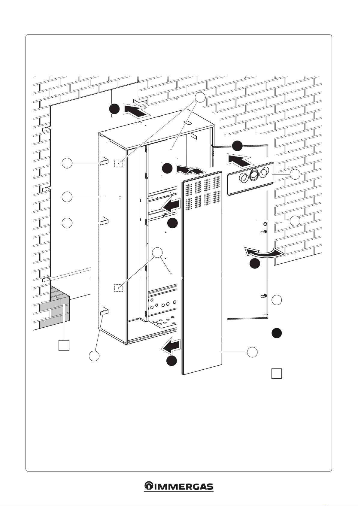
Predisporre le opere murarie creando un'apertura nella parete
dove verrà installato il telaio (1), facendo attenzione a preve-
dere lo spazio per i sei spacchi per inserire le rispettive alette
di sostegno (2) e uno spazio sotto il telaio suciente per poter
eettuare gli allacciamenti del kit (Fig. 4).
N.B.: è importantissimo prevedere un massetto di sostegno (A)
nella zona sottostante il Container Super Trio in corrispondenza
del punto d'appoggio dell'unità bollitore.
E' possibile inoltre ssare il telaio al muro mediante tasselli non
forniti utilizzando gli appositi quattro fori (6).
Il Container Super Trio viene chiuso dal coperchio latera-
le (5), dove è presente la griglia per l'aspirazione dell'aria,
dal coperchio superiore (3) dove è possibile far uscire la
fumisteria e dal portello (4) il quale è apribile mediante
la maniglia e solo dopo avere sbloccato le serrature po-
ste in verticale per poter accedere ai componenti interni.
Internamente sono presenti delle appendici (7) predisposte per
l’aggancio dei vari componenti.
Attenzione: L’installazione del Container Super Trio all’inter-
no della parete, deve garantire un sostegno stabile ed ecace
all'apparecchio contenuto al suo interno. Il presente kit assicura
un adeguato sostegno solo se inserito correttamente (secondo
le regole della buona tecnica) e posizionato in squadro rispetto
al muro seguendo le istruzioni di seguito riportate, garantendo
così la corretta funzionalità dei portelli anteriori. Il Container
Super Trio non è una struttura portante e non può sostituire
il muro asportato, è quindi necessario vericarne il proprio
posizionamento all’interno della parete.
Per motivi di sicurezza è necessario sigillare opportunamente il
vano di alloggiamento del Container Super Trio nella parete in
muratura, in ottemperanza alle normative vigenti.
Assicurarsi che le pretranciature per i collegamenti idraulici
siano state rimosse in corrispondenza del percorso tubi previ-
sto. Assicurarsi di asportare i relativi tranci in funzione della
canna fumaria (installazioni “tipo B” e “tipo C”) e dei condotti
di aspirazione (solo per installazione “tipo C”). Inserire il telaio
nella propria sede ricordandosi di aprire le sei alette di sostegno
(2) prima di inserirlo.
Alcuni fori sono pretranciati più piccoli rispetto alla misura
utile per dare la possibilità di essere allargati secondo le proprie
esigenze.
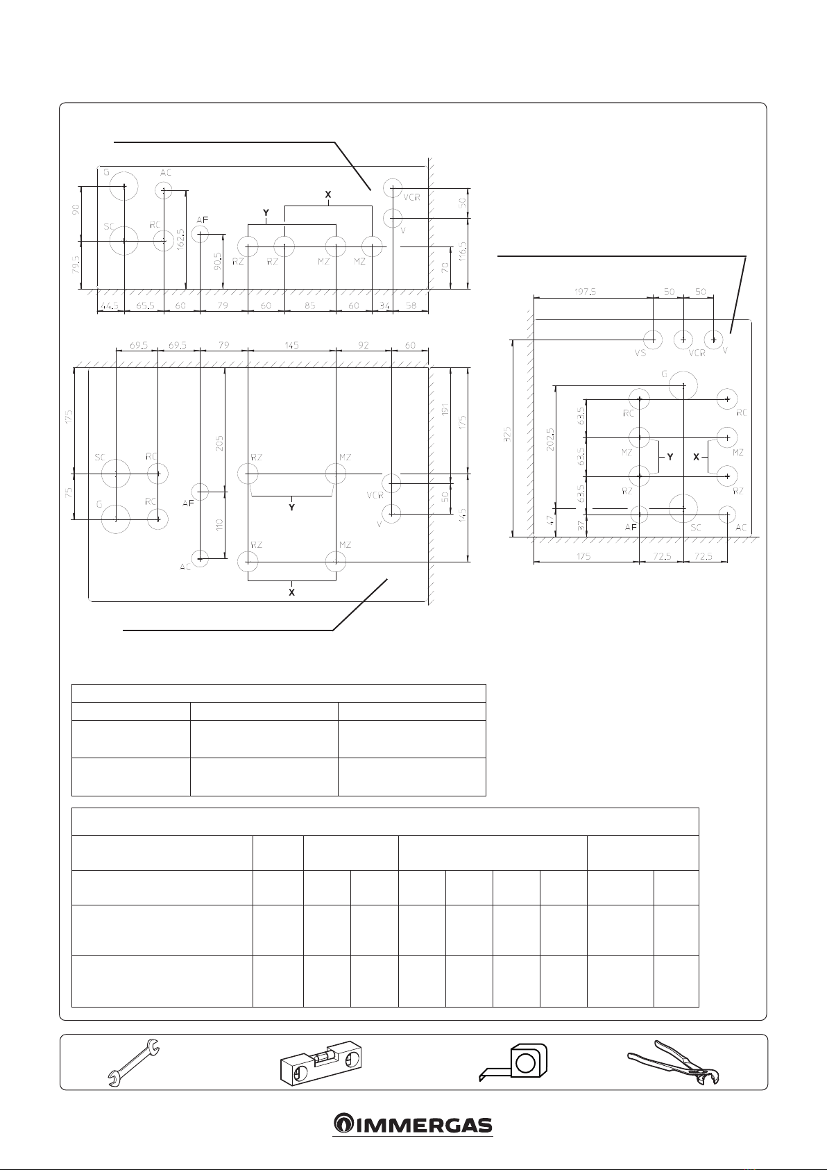
Eettuata l’installazione del telaio è necessario predisporre
tutte le connessioni per il collegamento idraulico allo specico
prodotto prescelto nella parte inferiore e laterale.
N.B.: Il gruppo di allacciamento non è a corredo, ma venduto
separatamente (optional). Per facilitare l’installazione è possibile
scegliere se operare l’allacciamento nella parte posteriore, nella
parte inferiore o laterale (in basso a destra) del Container Super
Trio (vedi Fig.3).
Per i collegamenti elettrici separare la connessione alla rete elet-
trica e dell’allacciamento alla termoregolazione facendo passare
i cavi nelle varie aperture previste.
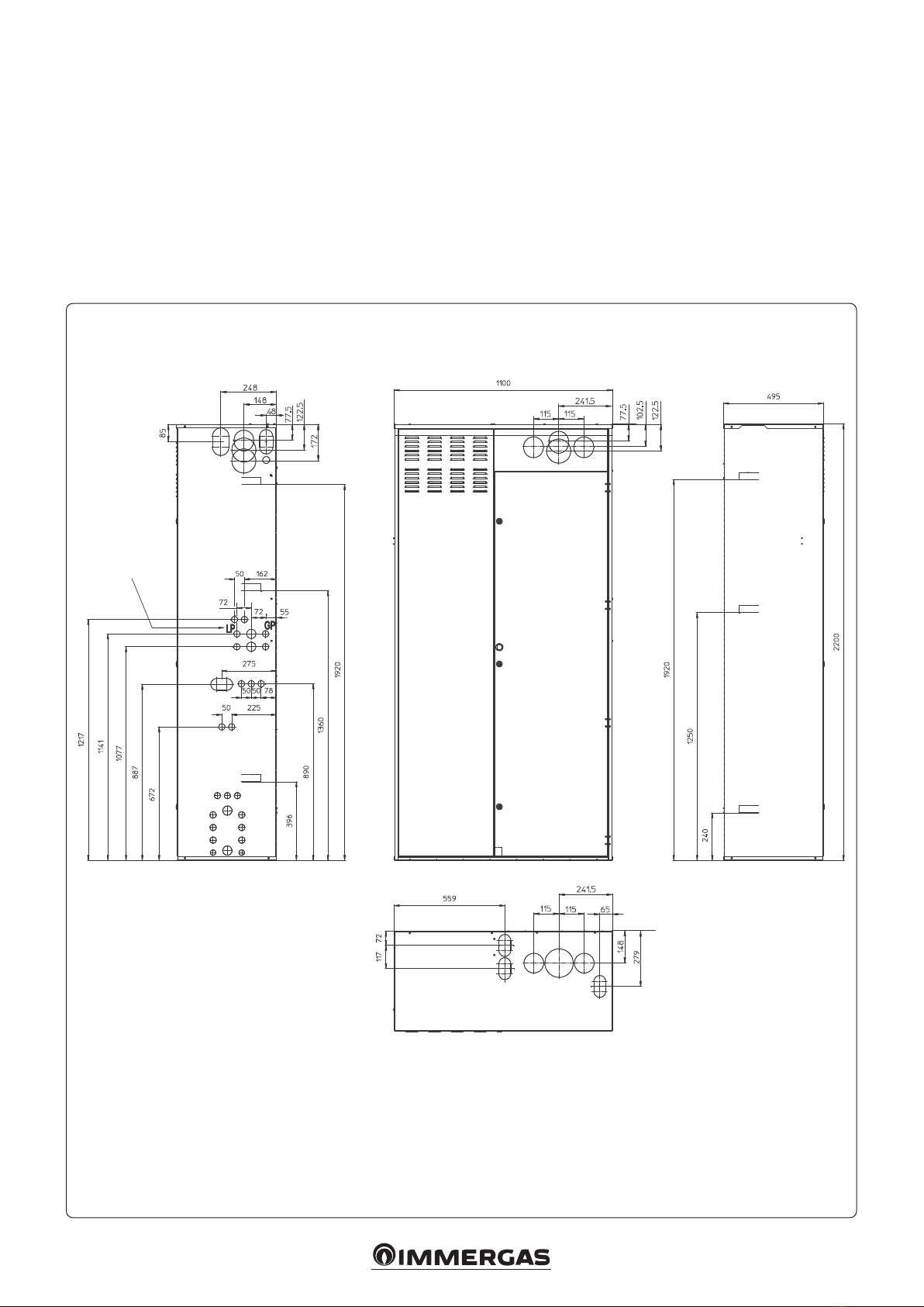
Eettuare l’allacciamento gas (dove richiesto). Il tubo gas può
uscire verso il basso, attraverso l'uscita posteriore, l'uscita infe-
riore, l’uscita laterale destra oppure frontalmente utilizzando
l’apposito pre-trancio già previsto sul portello (vedi gure di
seguito).
E’ possibile, una volta usciti frontalmente, far girare il tubo del
gas nella direzione preferita
N.B.: Per l’installazione del tubo di alimentazione gas, sotto
o fuori traccia, rispettare le norme d’installazione UNI 7129 /
7131-99.
Installare i tubi di collegamento del circuito gas refrigerante
utilizzando le forature predisposte. Le tubazioni devono spor-
gere all'interno del Container Super Trio quanto necessario per
permettere l'allacciamento al prodotto prescelto.
N.B.: Per l’installazione del circuito gas refrigerante e colle-
gamento a pompa di calore rispettare le Norme UNI EN 378.
Attenzione: Per il montaggio/installazione e messa in servizio
dei vari componenti all’interno del Container Super Trio si ri-
manda allo specico libretto istruzioni di ogni singolo prodotto.
Una volta terminati gli allacciamenti, assemblare la fumisteria se-
guendo le istruzioni riportate sul libretto istruzioni della caldaia.
Come ultima operazione chiudere il telaio utilizzando il portello
frontale
A questo punto l’installazione è completata ed è possibile
tinteggiare la copertura del telaio a seconda delle proprie ne-
cessità

7
Fig. 4
2b
d
c
e
c
1
2
6
25
4
3
6
A
a
Legenda disegni
installazione:
Identicazione
univoca
componente
Identicazione
sequenziale
operazione
da svolgere
Identicazione
componente
generico o
non fornito
in dotazione
1
a
A

8
Fig. 5 Fig. 6
Fig. 7 Fig. 8

9
THIS SHEET MUST BE LEFT WITH THE USER ALONG WITH THE INSTRUCTIONS MANUAL FOR THE FINISHED PRODUCT
IE
GENERAL WARNINGS.
All Immergas products are protected with suitable transport
packaging.
e material must be stored in a dry place protected from the
weather.
This instruction manual provides technical information for
installing the Immergas kit. As for the other issues related to kit
installation (e.g. safety at the workplace, environmental protection,
accident prevention), it is necessary to comply with the provisions
specied in the regulations in force and with the principles of good
practice.
Improper installation or assembly of the Immergas appliance and/
or components, accessories, kits and devices can cause unexpected
problems for people, animals and objects. Read the instructions
provided with the product carefully to ensure proper installation.
Installation and maintenance must be performed in compliance
with the regulations in force, according to the manufacturer's in-
structions and by professionally qualied sta, meaning sta with
specic technical skills in the plant sector, as envisioned by the law.

10
GENERALITIES.
e Super Trio Container has been designed to keep the instal-
lation space in external and internal walls to a minimum for
Magis Combo and Magis Pro.
e lower part of the frame is equipped with the holes necessary
for the hydraulic, gas, electrical connections, condensate drain
and for the connection of the thermoregulation.
In its right side part it is equipped with the holes necessary for
connections to the heat pumps.
e upper part has the holes for the outlet to the ue (“B type”
and “C type” installations) and to the intake duct (only for “C
type” installation) using the Immergas ue.
ATTENTION: it is not possible to exit on the le side with
the ue / ue gas kits and with the solar connection pipes.
MAIN DIMENSIONS.
Fig. 1
External unit
connection

11
MINIMUM INSTALLATION DISTANCE.
ATTENTION
Place the le side of the Container at least 100 mm away from the wall
to allow normal maintenance operations.
Fig. 2

12
CONNECTION TEMPLATE.
Fig. 3
RIGHT HAND SIDE CONNECTION
REAR CONNECTION
LOWER CONNECTION
ZONE CONNECTION TABLE.
Zona Y Zona X
Magis Combo Plus Zone 2 mixed
(Optional) Zone 1 direct
Magis Pro Zone 2 mixed
(Optional) Zone 1 direct
ATTACCHI
GAS
WATER
DOMESTIC CW
SYSTEM CONDENSING
UNIT
GAC AF RZ
(Y)
MZ
(Y)
RZ
(X)
MZ
(X) LP GP
Magis Combo Plus 4-6-9
Magis Pro 4-6-9
(with Super Trio)
G 1/2" G 1/2" G 1/2" G 3/4" G 3/4" G 3/4" G 3/4" 3/8" SAE 5/8”
SAE
Magis Combo Plus 12-14-16
Magis Pro 12-14-16
(with Super Trio Top)
G 1/2" G 1/2" G 1/2" G 1" G 1" G 1" G 1" 3/8" SAE 5/8”
SAE
Key:
G - Gas supply
AC - Domestic hot water outlet
AF - DHW (Domestic hot water) water inlet
LP - Chiller line - liquid phase
GP - Chiller line - gaseous phase
MZ - System ow
MZ - System ow
RZ - System return
RZ - System return
RC - DHW (Domestic hot water) recirculation
SC - Condensate drain
V - Electrical connection
VCR - Comando Amico Remoto remote control
VS - 3 bar discharge valve

13
INSTALLATION:
Set-up the masonry jobs creating an opening in the wall where
the frame will be installed (1), paying attention to envision the
space for the six slots for inserting the respective support ns
(2) and a space under the frame sucient to carry out the kit
connections (Fig. 4).
N.B.: it is very important to provide a support screed (A) in
the area under the Super Trio Container at the support point
of the storage tank.
It is also possible to x the frame to the wall with plugs (not
supplied) using the special four holes Ø 8 mm (6).
e Super Trio Container is closed by the side cover (5), where
the air intake grid is present, by the upper cover (3) where it
is possible to let the ue out and by the door (4) which can be
opened using the handle and only aer having unlocked the
vertical locks in order to access the internal components.
Internally there are appendices (7) prepared for the attachment
of the various components.
Attention: e installation of the Super Trio Container inside
the wall, must guarantee a stable and eective support to the
appliance it contains. is kit only ensures adequate support
if it is inserted properly (according to good practice rules)
and positioned in square with respect to the wall following
the instructions given below, thus guaranteeing the correct
functionality of the front doors. e Super Trio Container is
not a supporting structure and cannot replace the piece of wall
removed. It is therefore necessary to check its correct positioning
inside the wall.
For safety reasons, it is necessary to carefully seal the housing
compartment of the Super Trio Container in the wall, in com-
pliance with Standards in force.
Make sure that the knockouts for the hydraulic connections
have been removed at the intended pipe path. Be sure to remove
the relevant sections based on the ue (“B type” and “C type”
installations) and the intake ducts (only for “C type” installation).
Make sure that the pre-cuts for the various connections have
been removed from the intended route.
Insert the frame inside its own seat, remembering to open the
six support ns (2) before inserting it.
Aer installing the frame, it is possible to insert the thermal kits
by hooking them to the provided hooks.
Now make the connections according to your needs.
Some holes are pre-cut smaller with respect to the useful size
in order to allow them to be enlarged according to your needs.
Once the frame has been installed, it is necessary to prepare
all the connections for the hydraulic connection to the specic
product selected in the lower and lateral part.
N.B.: e connection unit is not supplied, but is sold separately
(optional). To ease installation, choose whether to make the
connection at the rear, bottom or side (bottom right) of the
Container Super Trio (see Fig. 3).
For electrical connections, separate the connection to the
electricity grid and the connection to the temperature control
by passing the cables through the various openings provided.
Make the gas connection (where required). e gas pipe can
exit downwards, through the rear outlet, lower outlet, right side
outlet or from the front using the appropriate pre-cut already
provided on the door (see gures below).
Once out from the front, it is possible to turn the gas pipe in the
preferred direction.
N.B.: to install the gas supply pipe, under or out of route, comply
with the installation standards UNI 7129 / 7131-99.
Install the refrigerant gas circuit connection pipes using the
pre-drilled holes. e pipes must protrude inside the Solar
Container kit as much as necessary to allow connection to the
chosen product
N.B.: For the installation of the refrigerant gas circuit and
connection to the heat pump, comply with the UNI EN 378
Standards.
Attention: For assembly / installation and commissioning of the
various components inside the Super Trio Container, please refer
to the specic instruction booklet of each individual product.
Once the connections have been made, assemble the ue ac-
cording to the instructions in the boiler instructions manual.
Lastly, close the frame using the front door.
At this point, the installation is complete and the frame cover
can be painted according to requirements and taste.

14
2b
d
c
e
c
1
2
6
25
4
3
6
A
a
Fig. 4
1
a
A
Drawings key
installation:
Unambiguous
component
identication
Sequential
identication of
the operation
to perform
Identication
of generic or
not supplied
componenent

15
Fig. 5 Fig. 6
Fig. 7 Fig. 8

Nel corso della vita utile dei prodotti, le prestazioni sono
inuenzate da fattori esterni, come ad es. la durezza dell'acqua
sanitaria, gli agenti atmosferici, le incrostazioni nell'impianto
e così via. I dati dichiarati si riferiscono ai prodotti nuovi e
correttamente installati ed utilizzati, nel rispetto delle norme
vigenti.
N.B.: si raccomanda di fare eseguire una corretta
manutenzione periodica.
During the useful life of the products, performance is aected
by external factors, e.g. the hardness of the DHW, atmospheric
agents, deposits in the system and so on. e data declared
refer to new products that are correctly installed and used with
respect to the Standards in force.
N.B.: correct periodic maintenance is highly recommended.
Cod. 1.043593 - rev. ST.004532/006 - 04/22
immergas.com
Per richiedere ulteriori approfondimenti specici, i Professionisti
del settore possono anche avvalersi dell’indirizzo e-mail:
To request further specic details, sector Professionals can also
Immergas S.p.A.
42041 Brescello (RE) - Italy
Tel. 0522.689011
Fax 0522.680617
Azienda certicata ISO 9001
ISO 9001 certied company
Il librettoistruzioni è realizzato incarta ecologica.
e instruction manual is printed on environmental-
ly-friendlypaper.
Table of contents
Languages:
Other Immergas Storage manuals

Immergas
Immergas 3.022167 Product manual

Immergas
Immergas UB 1000 V2 Operating instructions

Immergas
Immergas INOXSTOR 200 V2 Operating instructions

Immergas
Immergas 3.027290 User manual

Immergas
Immergas UB INOX 80 ErP User manual

Immergas
Immergas BASIC MAGIS PRO Product manual

Immergas
Immergas Hercules Condensing 26 2 E User manual