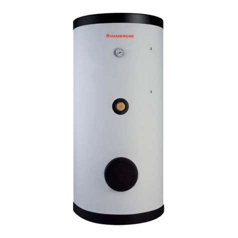
Immergas UB INOX 80 ErP User manual

*1.038279ENG*
Instruction and
recommendation booklet
IE UB INOX
80-120-200 ErP
Storage tank


Dear Customer,
Our compliments for having chosen a top-quality Immergas product, able to assure well-being and safety for a long period of time. As an Immergas customer
you can also count on a qualied aer-sales service, prepared and updated to guarantee constant eciency of your storage tank.
Read the following pages carefully: you will be able to draw useful suggestions regarding the correct use of the storage unit, the respect of which, will conrm
your satisfaction for the Immergas product.
For any interventions or routine maintenance contact Authorised Centres: these have original spare parts and boast of specic preparation directly from the
manufacturer.
General recommendations
All Immergas products are protected with suitable transport packaging.
e material must be stored in dry environments protected against bad weather.
e instruction book is an integral and essential part of the product and must be consigned to the new user also in the case of transfer or succession of ownership.
It must be stored with care and consulted carefully, as all of the warnings provide important safety indications for installation, use and maintenance stages.
is instructions manual provides technical information regarding installation of Immergas storage tank units. As for the other issues related to installation
of the said storage tank units (e.g. safety in the work site, environment protection, injury prevention), it is necessary to comply with the provisions specied in
the regulations in force and principles of good practice.
In compliance with legislation in force, the systems must be designed by qualied professionals, within the dimensional limits established by the Law. Instal-
lation and maintenance must be performed in compliance with the regulations in force, according to the manufacturer’s instructions and by an authorised
company, which has specic technical expertise in the system sector, as required by Law.
Improper installation or assembly of the Immergas appliance and/or components, accessories, kit and devices can cause unexpected problems to people, animals
and objects. Read the instructions provided with the product carefully to ensure a proper installation.
Maintenance must be carried out by an authorised company. e Authorised Aer-sales Service represents a guarantee of qualication and professionalism.
e appliance must only be destined for the use for which it has been expressly declared. Any other use will be considered improper and therefore potentially
dangerous.
If errors occur during installation, operation and maintenance, due to non compliance with technical laws in force, standards or instructions contained in this
book (or however supplied by the manufacturer), the manufacturer is excluded from any contractual and extra-contractual liability for any damages and the
appliance warranty is invalidated.
For further information regarding legislative and statutory provisions relative to the installation of gas heat generators, consult the Immergas site at the fol-
lowing address: www.immergas.com.
Mauro Guareschi
Research & Development Director
Signature:
Immergas S.p.A. declines all liability due to printing or transcription errors, reserving the right to make any modications to its technical and commercial
documents without forewarning.
CE DECLARATION OF CONFORMITY
(In compliance with ISO/IEC 17050-1)
e company IMMERGAS S.p.A., with registered oce in via Cisa Ligure 95 42041 Brescello (RE) whose design, manufacturing, and aer sale assistance
processes comply with the requirements of standard UNI EN ISO 9001:2008,
DECLARES that:
e UB INOX 80-120-200 ErP model of storage tank units comply with the following European Directives and Delegated European Regulations:
“Eco-design” Directive 2009/125/EC, “energy labelling” Directive 2010/30/EC, EU Regulation 812/2013, and EU Regulation 814/2013.

INDEX
USER pageINSTALLER page MAINTENANCE TECHNICIAN page
1 Storage tank unit installation...................5
1.1 Installation recommendations.................5
1.2 Main dimensions.......................................5
1.3 Connection group. ....................................6
1.4 System lling..............................................6
1.5 Domestic hot water storage tank unit. ...6
1.6 Solar control unit installation.
(Optional for UB INOX 120-200 ErP
models only). .............................................7
1.7 Hydraulic circuit resistance. ....................8
1.8 Kits available on request...........................8
1.9 Main components. .................................... 9
2 Instructions for use and maintenance..10
2.1 Cleaning and maintenance. ...................10
2.2 Emptying the storage tank unit.............10
2.3 Case cleaning...........................................10
2.4 Decommissioning. ..................................10
2.5 Control panel...........................................10
3 Control and maintenance ......................11
3.1 Hydraulic diagram. .................................11
3.2 Yearly appliance check
and maintenance. ....................................11
3.3 Casing removal........................................12
3.4 Replacing the anode................................12
3.5 Technical data..........................................12
3.6 Product data sheet (in compliance with
regulation 812/2013)...............................13

5
1-1
INSTALLERUSER
MAINTENANCE TECHNICIAN
1STORAGE TANK UNIT
INSTALLATION
1.1 INSTALLATION
RECOMMENDATIONS.
Only professionally enabled companies are au-
thorised to install Immergas appliances.
Installation must be carried out according to the
Standards, current legislation and in compliance
with local technical regulations and the required
technical procedures.
Before installing the appliance, ensure that it is
delivered in perfect condition; if in doubt, contact
the supplier immediately. Packing materials
(staples, nails, plastic bags, polystyrene foam,
etc.) constitute a hazard and must be kept out of
the reach of children.
If the appliance is installed inside or between
cabinets, ensure sufficient space for normal
servicing; therefore it is advisable to leave a gap
of 2÷3 cm between the storage tank casing and
the sides of the cabinet.
In the event of a malfunction, fault or incorrect
-operation, disable the storage tank unit and
contact an authorised company (e.g. the
Authorised Technical Assistance centre, which
has specically trained sta and original spare
parts). Do not attempt to modify or repair the
appliance alone.
Failure to comply with the above implies personal
liability and invalidates the warranty.
• Installation Standards: These storage tanks
have been designed for oor installation; they
must be used for the storage of domestic hot
water and similar purposes. ey have not be
designed for wall-installation.
Important: these units are used to store water at
a temperature below boiling point at atmospheric
pressure. ey must be connected to a boiler and
to a DHW water distribution network. ey must
be installed in rooms where the temperature
cannot fall below 0°C and must not be exposed
to atmospheric agents.
80 litre stainless steel storage tank unit
200 litre stainless steel storage tank unit
120 litre stainless steel storage tank unit
Key:
V - Electrical connection
AC - Domestic hot water outlet
AF - Domestic hot water inlet
RU - Return from storage tank unit
MU - Flow to storage tank unit
RP - Return to solar panels (Optional)
MP - Flow from solar panels (Optional)
RC - Domestic hot water pump (Optional)
1.2 MAIN DIMENSIONS.
CONNECTIONS
SYSTEM DOMESTIC HOT WATER
MU-RU MP-RP AF AC RC
3/4” 3/4” 3/4” 3/4” 1/2”

6
1-2
V
RU MU
RP MP RC
AF
AC
INSTALLERUSER
MAINTENANCE TECHNICIAN
Hydraulic connection. Before making the
connections, all of the system piping must be
washed thoroughly to remove any residues that
could compromise the good functioning of the
storage tank. Water connections must be made in
a rational way using the couplings on the storage
tank template. e storage tank safety valve outlet
must be connected to a draining funnel. If this
is not the case, the storage tank manufacturer
declines any liability in the event of ooding if
the drain valve cuts in.
1.4 SYSTEM FILLING.
Once the storage tank has been connected, ll
the system via the boiler lling valve. Filling is
performed at low speed to ensure release of air
bubbles in the water via the boiler and central
heating system vents.
Close the lling valve when the boiler manometer
pointer indicates approx. 1.2 bar (see boiler
instruction book).
1.5 DOMESTIC HOT WATER STORAGE
TANK UNIT.
e storage tank unit must be connected to a
boiler. It contains large coiled stainless steel heat
exchanger pipes, which allow to notably reduce
hot water production times. is storage tank
unit, manufactured with stainless steel casing and
bottoms, guarantees long duration through time.
e assembly concepts and welding (T.I.G.) are
implemented to the minimum detail to ensure
maximum reliability.
e upper inspection ange ensures practical
control of the storage tank unit and the coil heat
exchanger pipe and easy internal cleaning.
e domestic hot water connections are placed
on the ange cover (cold inlet and hot outlet), the
Magnesium Anode cap inclusive of the same, is
provided as standard for the internal protection
of the storage tank from possible corrosion is
located on the side of the UB INOX 200 ErP
storage tank, in the other models is placed on
the inspection ange.
N.B.: annually check (e.g. the Authorised
Technical Assistance centre) eciency of the
sacrificial anodes. The storage tank unit is
prepared for introduction of the domestic hot
water pump tting.
1.3 CONNECTION GROUP.
Key:
V - Electrical connection
AC - 3/4'' DHW outlet
RU - 3/4" return from storage tank
MU - 3/4" ow to storage tank
AF - 3/4'' DCW inlet
RP - 3/4" solar panels return (optional per UB INOX 120-200 ErP)
MP - 3/4" solar panels ow (optional per UB INOX 120-200 ErP)
RC - 1/2” recirculation (optional)

7
1-4
1-3
225
226
227
228
229
224
221
222
223
223
INSTALLERUSER
MAINTENANCE TECHNICIAN
Solar control unit xing.
Hole plug plaque removal.
1.6 SOLAR CONTROL UNIT
INSTALLATION.
(Optional for UB INOX 120-200 ErP
models only).
Using the solar control unit it is possible to couple
the UB INOX 120-200 ErP storage tank units to
a solar system.
Hole plug plaque removal (Fig. 1-3).
- Remove the casing as indicated in paragraph
3.3 of this book;
- Take the front casing (1) and remove the hole
plug plaque (2) unscrewing the 3 xing screws
(3).
Solar control unit xing (Fig. 1-4).
- Fix the screw (8) onto the support sheet steel
(9) paying attention to leave a couple of mm
between the head of the screw and the support
sheet steel;
- Remove the lid (6) from the solar control unit
(7) loosening the screw (5);
- Attach the upper part of the solar control unit
(7) to the screw (8);
- Block the solar control unit (7) in the lower
part using the screw (4);
- Make all electric connections as indicated in
the solar control unit instruction book;
- Re-mount the lid (6) from the solar control unit
(7) loosening the screw (5);
- Re-mount the storage tank unit casing.

8
1-5
A
A
A
UB INOX 80 ErP
UB INOX 200 ErP
UB INOX 120 ErP
INSTALLERUSER
MAINTENANCE TECHNICIAN
Hydraulic circuit resistance.
A - Storage tank unit
hydraulic circuit resistance
1.7 HYDRAULIC CIRCUIT RESISTANCE.
In order to guarantee sucient DHW ow rate,
it is important to consider the resistance of the
storage tank hydraulic circuit to be coupled to
the boiler. (Fig. 1-5). For correct connection of
the storage tank unit to Immergas boilers, see the
boiler instruction book.
1.8 KITS AVAILABLE ON REQUEST.
• Pump kit (on request). e storage tank unit
is prepared for application of the pump kit.
Immergas supplies a series of fittings and
attachments that allow connection between
the storage tank unit and domestic hot water
system. The pump kit attachment is also
envisioned on the template.
• Column attachment kit (on request for UB
INOX 200 ErP) A vertical connection kit is
envisioned for the connection of the storage
tank unit to the column, which allows to
connect the storage tank unit directly to the
boiler without having to insert the connection
pipes into the wall.
• Solar collectors kit (on request for UB INOX
120-200 ErP) On request Immergas supplies
complete packs for set-up, if solar collectors
are to be used for the production of domestic
hot water.
• Double storage tank kit in parallel (on request
for UB INOX 200 ErP) A connection kit is
envisioned for the connection of two storage
tank units in parallel, which allows connection
of the two storage tank units directly to the
boiler without having to insert the connection
pipes into the wall.
• Solar panels kit in parallel (on request for UB
INOX 200 ErP) For the connection of two
storage tank units to the solar panels without
having to insert the connection pipes into the
wall.
• Storage tanks pump kit in parallel (on request
for UB INOX 200 ErP) For the connection
of two storage tank units to the recirculation
pump pipes without having to insert the
connection pipes into the wall.
• Electronic anode kit (on request).
(Not available for UB INOX 80 ErP).
Direct current is made to circulate between the
device and the tank to be protected via a special
titanium anode.
Use the tting present on the storage tank upper
ange for installation of the anode (Free tting
for UB INOX 200 ErP, or replacing the anode
present in the UB INOX 120 ErP).
e above-mentioned kits are supplied complete
with instructions for assembly and use.
Head (kPa) Head (kPa) Head (kPa)
Flow rate (l/h)
Flow rate (l/h)
Flow rate (l/h)
Head (m H2O) Head (m H2O) Head (m H2O)
9
1-6
INSTALLERUSER
MAINTENANCE TECHNICIAN
1.9 MAIN COMPONENTS.
80 litre stainless steel storage tank unit 120 litre stainless steel storage tank unit
200 litre stainless steel storage tank unit
Key:
1 - Stainless steel coil for storage tank
2 - Domestic hot water probe
3 - Magnesium anode
4 - 8 bar safety valve
5 - Storage tank emptying cock
6 - ermometer probe
7 - DHW expansion vessel
8 - Coil that can be coupled to solar panels
9 - Solar panels probe (Optional)

10
2-1
INSTALLERUSER
MAINTENANCE TECHNICIAN
2INSTRUCTIONS FOR USE
AND MAINTENANCE.
2.1 CLEANING AND MAINTENANCE.
Attention: to preserve integrity of the storage
tank unit and keep the safety features, per-
formance and reliability, which distinguish it,
unchanged over time, you must at least execute
maintenance operations on a yearly basis in
compliance with what is stated in the relative
point at “annual check and maintenance of the
appliance”, in compliance with national, regional,
or local standards in force. Annual maintenance
is essential to validate the Immergas warranty.
We recommend stipulating a yearly cleaning
and maintenance contract with an authorised
local rm.
2.2 EMPTYING THE STORAGE TANK
UNIT.
To drain the storage tank, use the special
valve in the lower part of the storage tank
(Part. 5 Fig. 1-6).
Before draining, ensure that the DHW inlet
valve is closed.
2.5 CONTROL PANEL.
Key:
1 - Hole plug plaque
2 - Storage tank unit thermometer
2.3 CASE CLEANING.
Use damp cloths and neutral detergent to clean
the storage tank casing. Never use abrasive or
powder detergents.
2.4 DECOMMISSIONING.
In the event of permanent shutdown of the stor-
age tank, contact an authorised company for the
relative operations, among other things making
sure that water supply is disconnected.
At the end of its service life the appliance must
not be disposed of like normal household waste
nor abandoned in the environment, but must
be removed by a professionally authorised
company. Contact the manufacturer for disposal
instructions.

11
3-1
INSTALLERUSER
MAINTENANCE TECHNICIAN
3CONTROL
AND MAINTENANCE
3.1 HYDRAULIC DIAGRAM.
Key:
1 - Storage tank unit draining valve
2 - 8 bar safety valve
3 - Magnesium anode
4 - Domestic hot water expansion vessel
5 - Stainless steel coil for storage tank
6 - One-way valve (OV 20)
7 - Cold water inlet lter
8 - Cold water inlet cock
9 - Domestic hot water probe
10 - DHW inlet probe (Optional)
11 - Stainless steel coil that can be coupled
to solar panels
12 - System draining valve
13 - Solar panels probe (Optional)
3.2 YEARLY APPLIANCE CHECK AND
MAINTENANCE.
e following checks and maintenance should
be performed at least once a year.
- Visually check for water leaks or oxidation
from/on connections;
- Check visually that the safety and control
devices have not been tampered with and in
particular, the DHW regulation NTC probe;
- Check the integrity of the storage tank
Magnesium anode;
- Check the state of the internal coil;
- Check the presence of any slurry deposits on
the bottom of the storage tank.
AC - Domestic hot water outlet
RC - Pump (Optional)
AF - Domestic cold water inlet
MU - Flow to storage tank unit
RU - Return from storage tank unit
200 L STAINLESS STEEL STORAGE TANK UNIT 120 L STAINLESS STEEL STORAGE TANK UNIT 80 L STAINLESS STEEL STORAGE TANK UNIT

12
3-2
1
2
222
4
4
3
4
5
5
INSTALLERUSER
MAINTENANCE TECHNICIAN
3.3 CASING REMOVAL.
To facilitate storage tank maintenance, the casing
can be completely removed as follows:
N.B.: the casing removal procedure is the same
for all storage tank unit models.
- remove the lid (1) pulling it upwards;
- loosen the screws (2) and pull the front panel
outwards (3);
- loosen the screws (4) of the side pieces (5)
positioned on the top and in the lower part
of the side pieces themselves. Aer having
released them from the screws, they can be
removed by pulling them forward and then
upwards.
3.4 REPLACING THE ANODE.
e magnesium anode (Part. 3 Fig. 1-6), present
in the storage tank, must be replaced every year
with another having the same features.
3.5 TECHNICAL DATA.
UB INOX 80 ErP UB INOX 120 ErP UB INOX 200 ErP
Storage tank useful capacity l 80 120 200
Domestic hot water side maximum pressure bar 888
DHW side maximum temperature °C 99 99 99
Domestic hot water expansion vessel l 4.0 5.0 8.0
Dispersions kWh/24h 2.49 2.54 3.42
Coil thickness mm 0.8 0.8 0.8
Coil length mm 10350 - -
Lower coil length mm - 3850 6500
Upper coil length mm - 8400 10700
Coil exchange surface m20.65 - -
Lower coil exchange surface m2- 0.24 0.41
Upper coil exchange surface m2- 0.53 0.67
Coil capacity l 2.75 - -
Lower coil capacity l - 1.02 1.73
Upper coil capacity l - 2.23 2.84
Primary uid ow rate (coil) l/h 1030 1325 1390
Coil head loss at 1000 l/h kPa (m H2O) 13.2 (1.35) 7.1 (0.72) 8.3 (0.85)
Central heating side maximum pressure bar 666
Central heating side maximum temperature °C 90 90 90
Heat exchange maximum output kW 23.9 30.8 32.3
Reintegration heat output kW 15.7 18.8 20.2
Full weight kg 154.0 203.0 304.0
Empty weight kg 70.9 78.9 99.4
Total water content l 82.7 123.0 205.0

A
B
C
D
E
F
G
104 W
80 L
E
UB INOX 80 ErP
A
B
C
D
E
F
G
143 W
200 L
F
UB INOX 200 ErP
A
B
C
D
E
F
G
106 W
120 L
UB INOX 120 ErP
E
UB INOX 80 ErP
UB INOX 200 ErP
UB INOX 120 ErP
3.6 PRODUCT DATA SHEET IN COMPLIANCE WITH REGULATION 812/2013.


is instruction booklet is made of ecological paper Cod. 1.038279ENG - rev. ST.001937/000 - 05/15 - Inglese per IRLANDA (IE)
Follow us
Immergas Italia
immergas.com
Immergas S.p.A.
42041 Brescello (RE) - Italy
Tel. 0522.689011
Fax 0522.680617
Certified company ISO 9001
ИЗКЛЮЧИТЕЛЕН ПРЕДСТАВИТЕЛ И СЕРВИЗ
АМАКС ГАЗ ООД
1261 Мрамор, София ул В. Левски 148
Tel. 0700 112 66
Fax 02 902 46 70
www.amaxgas.com
Other manuals for UB INOX 80 ErP
1
This manual suits for next models
2
Table of contents
Other Immergas Storage manuals

Immergas
Immergas INOXSTOR 200 V2 Operating instructions

Immergas
Immergas 3.027290 User manual

Immergas
Immergas 3.022167 Product manual

Immergas
Immergas UB 1000 V2 Operating instructions

Immergas
Immergas COD. 3.030394 Product manual

Immergas
Immergas BASIC MAGIS PRO Product manual

Immergas
Immergas Hercules Condensing 26 2 E User manual
Popular Storage manuals by other brands

Spectra Logic
Spectra Logic Spectra 2k Replacement guide

Powerfix Profi
Powerfix Profi 93283 Assembly and Safety Advice

QNAP
QNAP TS-2888X Series user guide

HP
HP Surestore Disk Array 12h - And FC60 Configuration

Mercia Garden Products
Mercia Garden Products 01SHPCHEST instructions

QPS
QPS Que! M5 quick start guide