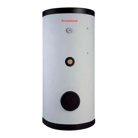
Immergas UB 1000 V2 Operating instructions

STORAGE
TANK UNIT
1000-1500-2000 V2
IE
Instruction and
recommendation booklet
*1.041262ENG*


Dear Customer,
Our compliments for having chosen a top-quality Immergas product, able to assure well-being and safety for a long period of time. As an Immergas customer
you can also count on a qualied aer-sales service, prepared and updated to guarantee constant eciency of your storage tank unit.
Read the following pages carefully: you will be able to draw useful tips on the proper use of the storage tank, compliance with which will conrm your satisfaction
with the Immergas product.
For assistance and scheduled maintenance contact Authorised Aer-Sales centres: they have original spare parts and are specically trained directly by the
manufacturer.
General recommendations
All Immergas products are protected with suitable transport packaging.
e material must be stored in dry environments protected against bad weather.
e instruction book is an integral and essential part of the product and must be consigned to the new user also in the case of transfer or succession of ownership.
It must be stored with care and consulted carefully, as all of the warnings provide important safety indications for installation, use and maintenance stages.
is instructions manual provides technical information regarding installation of Immergas storage tank units. As for the other issues related to installation
of the said storage tank units (e.g. safety in the work site, environment protection, injury prevention), it is necessary to comply with the provisions specied in
the regulations in force and principles of good practice.
In compliance with legislation in force, the systems must be designed by qualied professionals, within the dimensional limits established by the Law. Installation
and maintenance must be performed in compliance with the regulations in force, according to the manufacturer's instructions and by an authorised company,
which has specic technical expertise in the system sector, as required by Law.
Improper installation or assembly of the Immergas appliance and/or components, accessories, kit and devices can cause unexpected problems to people, animals
and objects. Read the instructions provided with the product carefully to ensure a proper installation.
Maintenance must be carried out by an authorised company. e Authorised Aer-sales Service represents a guarantee of qualication and professionalism.
e appliance must only be destined for the use for which it has been expressly declared. Any other use will be considered improper and therefore potentially
dangerous.
If errors occur during installation, operation and maintenance, due to non compliance with the technical laws in force, standards or instructions contained
in this manual (or however supplied by the manufacturer), the manufacturer accepts no contractual and extra-contractual liability for any damages and the
storage tank warranty is invalidated.
e manufacturer declines all liability due to printing or transcription errors, reserving the right to make any modications to its technical and com-
mercial documents without prior notice.

INDEX
USER page
INSTALLER page MAINTENANCE TECHNICIAN page
1 Storage tank unit installation.................... 5
1.1 Installation recommendations.................. 5
1.2 Main dimensions. ......................................6
1.3 connection..................................................6
1.4 Filling the system........................................6
1.5 Domestic hot water storage tank unit......7
1.6 Kits available on request. ...........................7
1.7 Main components....................................... 7
2 Use and maintenance instructions...........8
2.1 Cleaning and maintenance........................8
2.2 Operation.....................................................8
2.3 Emptying the storage tank unit. ...............8
2.4 Cleaning the case. ......................................8
2.5 Decommissioning.......................................8
3 Checks and maintenance...........................9
3.1 Functional layout........................................9
3.2 Yearly storage tank unit check
and maintenance.......................................10
3.3 Storage Tank Unit technical data............10

5
INSTALLERUSER
MAINTENANCE TECHNICIAN
1STORAGE TANK
UNIT INSTALLATION
1.1 INSTALLATION
RECOMMENDATIONS.
Only professionally enabled companies are au-
thorised to install Immergas appliances.
e place of installation of the appliance and
relative Immergas accessories must have suitable
features (technical and structural) such to allow
(always in safety, efficiency and comfortable
conditions):
- installation (according to the provisions of the
technical legislation and technical regulations);
- maintenance operations (including scheduled,
periodic, routine and special maintenance);
- removal (to outdoors in the place for loading
and transporting the appliances and compo-
nents) as well as their eventual replacement
with appliances and/or equivalent components.
Installation must be carried out according to
regulation standards, current legislation and
in compliance with local technical regulations
and the required technical procedures. Before
installing the storage tank unit, ensure that it is
delivered in perfect condition; if in doubt, contact
the supplier immediately. Packing materials (sta-
ples, nails, plastic bags, polystyrene foam, etc.)
constitute a hazard and must be kept out of the
reach of children.
If the storage tank unit is installed inside or
between cabinets, ensure there is sucient space
for normal servicing. It is advisable to leave an
adequate gap between the storage tank casing
and the sides of the cabinet.
In the event of malfunctions, faults or incorrect
operation, turn the storage tank o and contact
an authorised company (e.g. the Authorised
Technical Assistance centre, which has specical-
ly trained sta and original spare parts). Do not
attempt to modify or repair the appliance alone.
Failure to comply with the above implies personal
responsibility and invalidates the warranty.
• Installation standards: check the features of the
installation area in advance, in terms of overall
dimensions and weight of the cylinder, setting
up a supporting surface under the storage tank
if necessary, to optimise weight distribution.
ese storage tanks have been designed for
oor installation only; they must be used for
the storage of domestic hot water and similar
purposes. ey have not be designed for wall-
installation. Ensure that the useful heat output
of the generator is at least 15% higher than the
heat output that can be absorbed by the stor-
age tank, and that the volume and factory-set
pressure of the expansion tank of the secondary
circuit are suitable for the system;
Attention: this storage tank unit is designed to
produce and store hot water, it must therefore
be connected to a heating system, to a domestic
hot water distribution network and to the water
system, compatibly with its specications and
heat output. e materials used for installation
and connection must be fully compatible with the
minimum characteristics required for solar use.
It must also be installed in rooms where the
temperature cannot fall below 0°C. It must not
be exposed to the eects of the weather.
6
1-1
INSTALLERUSER
MAINTENANCE TECHNICIAN
1.3 CONNECTION.
Hydraulic connection. Before making the
connections, all of the system piping must be
washed thoroughly to remove any residues that
could compromise the proper operation of the
storage tank. Water connections must be made
in a rational way.
Attention: to preserve the duration and eciency
of the domestic hot water exchanger it is recom-
mended to install the “polyphosphate dispenser”
kit (or other device in compliance with Standard
in force and perfectly) in the presence of water
whose characteristics can give rise to scale deposits
(in particular, and as an example, the device is
recommended when water hardness is higher than
25 French degrees).
1.2 MAIN DIMENSIONS.
Key:
D - Storage tank diameter
H - Storage tank height
ISP - Inspection ange
E15 - Storage tank integration resistance
AF - Domestic cold water inlet
RP - Return from solar panels
MP - Flow to solar panels
RU - Return from storage tank
RC - Recirculation (Optional)
MU - Flow to storage tank
AC - Domestic hot water outlet
1.4 FILLING THE SYSTEM.
When the storage tank has been connected, ll
the system. Filling is performed at low speed to
ensure releasing any air bubbles contained in the
water through the vents installed on the central
heating system.
Close the lling valve when the boiler manom-
eter pointer indicates approx. 1.2 bar (see boiler
instruction book).
V2 Vitried steel Storage Tank Unit
UB 1000 V2
Vitried Storage
Tank (mm)
Ø
UB 1500 V2
Vitried Storage
Tank (mm)
Ø
UB 2000 V2
Vitried Storage
Tank (mm)
Ø
DØ 950 -- Ø 1200 -- Ø 1300 --
H2110 -- 2250 -- 2570 --
ISP 410 Ø 180 445 Ø 290 500 Ø 180
E15 1115 -- 1315 -- 1550 --
AF 180 1’’ 1/4 225 1” 1/2 460 2”
RP 375 1’’ 1/4 325 1” 1/4 570 1’’ 1/4
MP 1065 1’’ 1/4 1225 1” 1/4 1470 1’’ 1/4
RU 1170 1’’ 1/4 1395 1” 1/4 1670 1’’ 1/4
RC 1455 1’’ 1670 1” 600 1’’
MU 1620 1’’ 1/4 1815 1” 1/4 1970 1’’ 1/4
AC 1805 1’’ 1/4 1955 1” 1/2 2140 2”

7
1-2
INSTALLERUSER
MAINTENANCE TECHNICIAN
1.5 DOMESTIC HOT WATER STORAGE
TANK UNIT.
e storage tank unit must be connected to a
boiler and a solar panel system. It contains large
coiled heat exchanger pipes, which help notably
reduce hot water production times.
- Boiler protection:
- Vitried steel Storage Tank Units: treatment
with glazed enamel (also called vitrication),
gives the product a high capacity of inalter-
ability of the chemical-physical features of
the domestic hot water.
Additional quality support is provided by
magnesium anodes installed, by standard, on
the product. On request it is possible to install
impressed current anodes.
- Eciency: the coiled heat exchange surface is
sized to supply large quantities of hot water.
- Heat insulation: the storage tanks with a capac-
ity of 1000, 1500 and 2000 litres are insulated
with exible polyurethane with a thickness of
100 mm., CFC and HCFC-free.
- External casing: this is made of a coupled PVC
sheath.
N.B.: every year a skilled technician (e.g. Au-
thorised Aer-sales Service), must check the
eciency of the storage tank unit's Magnesium
Anode. e storage tank unit is prepared for
introduction of the domestic hot water pump
tting.
1.6 KITS AVAILABLE ON REQUEST.
• Recirculation kit (on request). e storage tank
unit is prepared for application of the pump
kit. Immergas supplies a series of ttings and
attachments that allow connection between
the storage tank unit and domestic hot water
system. e pump kit attachment is also envi-
sioned on the template.
• Solar panels kit (on demand). If solar panels
are to be used for the production of domestic
hot water, Immergas supplies the solar panels
kit on demand.
e above-mentioned kits are supplied complete
with instructions for assembly and use.
1.7 MAIN COMPONENTS.
Key:
1 - Inspection ange
2 - Magnesium anode
3 - Insulating material
4 - Storage tank coil
5 - DHW probe (NTC 10 k hom at 25°C
supplied as per standard)
6 - Solar panels coil
7 - Solar panel probe
8 - Storage tank unit draining valve
9 - Magnesium anode (UB 1500 - UB 2000 V2)
UB 1000 - 1500 - 2000 V2 Vitried Storage Tank

8
INSTALLERUSER
MAINTENANCE TECHNICIAN
2USE AND MAINTENANCE
INSTRUCTIONS
2.1 CLEANING AND MAINTENANCE.
e user is advised to service the storage tank
unit on an annual basis.
is ensures that the optimal safety, performance
and operation characteristics of the storage tank
unit remain unchanged over time.
2.2 OPERATION.
is storage tank allows easy provisioning of
water for domestic use and industrial use.
e storage tank is connected to the water dis-
tribution network via the cold water tting and
to the utilities via the hot water tting.
If a utility withdraws hot water, the cold water
enters the tank where it is heated to the tempera-
ture set on the thermostat.
It is recommended to adjust the temperature
between 60 and 65°C because this temperature
guarantees the best performance of the storage
tank unit and at the same time ensures:
- maximum hygiene
- maximum savings
- delay in lime scale formation
e DHW in the storage tank is heated with
the passage of CH/solar water, which circulates
inside the coils inside the storage tank unit itself.
In all cases the maximum temperature inside the
storage tank unit must not exceed 99 °C.
2.3 EMPTYING THE STORAGE TANK
UNIT.
To drain the storage tank, use the special drain-
ing valve in the lower part of the storage tank.
Before draining, ensure that the DHW inlet
valve is closed.
2.4 CLEANING THE CASE.
To clean the outer parts of the storage tank, just
use a cloth dampened with product suitable for
the purpose that can be found on the market.
Abrasive, solvents, petrol and alcohol products
are not recommended.
2.5 DECOMMISSIONING.
In the event of decommissioning the storage
tank, contact an authorised company for the
relative operations, among other things making
sure that water supply is disconnected.
At the end of its service life the appliance must
not be disposed of like normal household waste
nor abandoned in the environment, but must
be removed by a professionally authorised
company. Contact the manufacturer for disposal
instructions.

9
1
35
24
8
A
7
1
10
13
12
9
11
AF
AC
MU
RU
RP
MP
6
3-1
INSTALLERUSER
MAINTENANCE TECHNICIAN
3CHECKS AND
MAINTENANCE
3.1 FUNCTIONAL LAYOUT.
e following is an example of the connection of
the storage tank unit coupled with a solar panel
heating system (Fig. 3-1).
Key:
1 - Solar collectors
2 - Electronic control unit
3 - Solar circulation unit
4 - Solar system expansion vessel
5 - 6 bar safety valve
6 - System probe and venting unit
7 - Mixing valve
8 - V2 Storage tank unit
9 - Storage tank unit thermometer
10 - Inspection ange
11 - Magnesium anode tting
12 - DHW probe tting (NTC 10 k hom at
25°C supplied as per standard)
13 - Solar panel probe tting
AC - Domestic hot water outlet
AF - Domestic cold water inlet
MU - Storage tank unit ow
RU - Storage tank unit return
MP - Flow from solar panels
RP - Return to solar panels

10
INSTALLERUSER
MAINTENANCE TECHNICIAN
3.2 YEARLY STORAGE TANK UNIT
CHECK AND MAINTENANCE.
e following checks and maintenance should
be performed at least once a year.
- Check for water leaks or oxidation from/on the
ttings;
- Visually check that the safety and control
devices have not been tampered with, in par-
ticular:
- adjustment probes;
- expansion vessel;
- safety valve on D.H.W. side;
- Check the integrity of the storage tank Magne-
sium Anode.
- In case of particularly hard water it is advisable
to remove the lime scale from the storage tank
at least once a year. To do so, it is necessary to
empty the tank from the draining valve, remove
the ange to access the inside, and then use a
plastic or wooden spatula to remove the most
stubborn sediments, then clean and rinse again
with a jet of water.
- During cleaning, be very careful not to damage
the protection inside the tank.
3.3 STORAGE TANK UNIT TECHNICAL DATA
- When you have completed the process, put the
ange back in place using the gasket (it if is
damaged, replace it with a new one), close the
draining valve and ll the tank ensuring that
neither ange or valve are leaking.
UB 1000 V2
Vitried Storage Tank
UB 1500 V2
Vitried Storage Tank
UB 2000 V2
Vitried Storage Tank
Storage tank unit capacity l 888.5 1388 2032
Domestic hot water side maximum pressure bar 8 8 8
DHW side maximum temperature °C 99 99 99
Maximum coil pressure bar 8 8 8
Central heating side maximum temperature °C 99 99 99
Upper coil exchange surface m21.60 2.3 2
Upper coil capacity l 10 19.7 15.8
Lower coil exchange surface m22.8 3.9 5.9
Lower coil capacity l 17 33.4 45.4
Empty storage tank unit weight kg 302 345 390
Full storage tank unit weight kg 1191 1782 2422
Heat dispersion - Psbsol W/K 3.16 3.61 6.63

11

Follow us
Immergas Italia
immergas.com
Immergas S.p.A.
42041 Brescello (RE) - Italy
Tel. 0522.689011
Fax 0522.680617
Certied company ISO 9001
is instruction booklet is made of ecological paper Cod. 1.041262ENG - rev. ST.003317/000 - 09/17 - Inglese per IRLANDA (IE)
This manual suits for next models
5
Table of contents
Other Immergas Storage manuals

Immergas
Immergas INOXSTOR 200 V2 Operating instructions

Immergas
Immergas Hercules Condensing 26 2 E User manual

Immergas
Immergas COD. 3.030394 Product manual

Immergas
Immergas BASIC MAGIS PRO Product manual

Immergas
Immergas 3.027290 User manual

Immergas
Immergas UB INOX 80 ErP User manual

Immergas
Immergas 3.022167 Product manual
Popular Storage manuals by other brands

kioxia
kioxia EXCERIA PLUS manual

Fujitsu
Fujitsu ETERNUS DX S5 Series Operation Guide (Basic

Spectra Logic
Spectra Logic 10K Library Preventative Maintenance Guide

Follett
Follett ITS500-31 Installation, operation, and parts manual

Tentacle
Tentacle Sync E operating manual

Hitachi
Hitachi Deskstar 7K80 Specifications