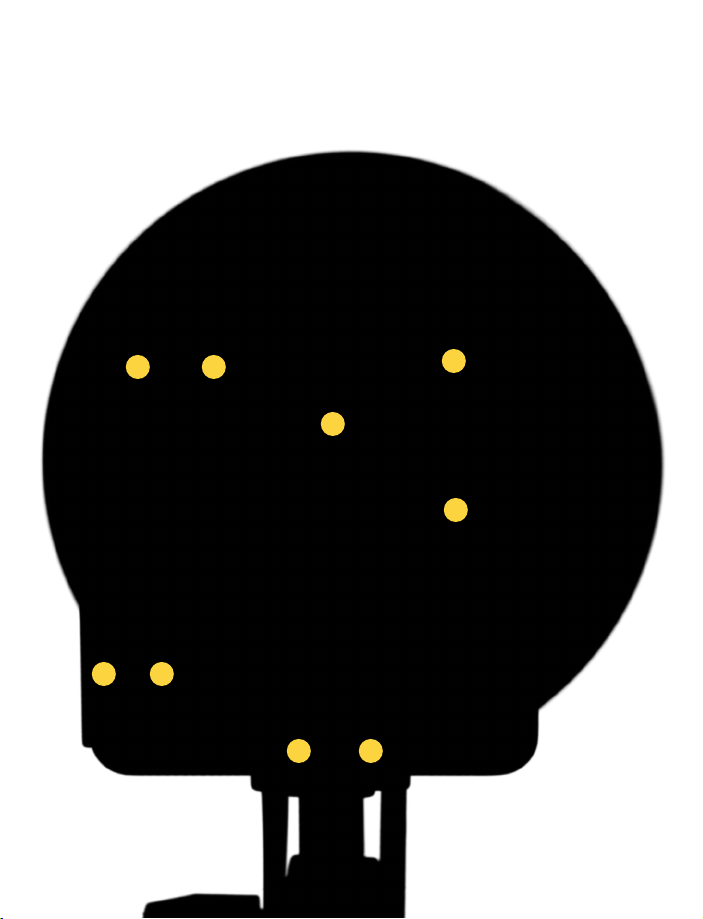
Legend
A – Recycle Indicator Light F – Fuse Holder
B – Photocell G – Power Socket
C – Power Regulator Dial H – On/Off Switch
D – Sync Jack I – Modeling Light Switch
E – Test Fire Button
Power Supply
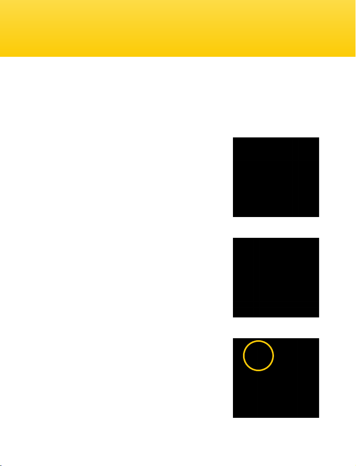
Plug the power cord into the back of the ash unit. Before plugging the power cord into
the wall socket, make certain that the power switch is set to the OFF (circle) position.
Note: The EX-100A flash unit comes in two designs; one is designed for use with 110/120V
AC power in the US and the other for use with 220V AC power in Europe. Neither model can
be used outside of its native power region.
Power Switch
Turn the power switch to the ON (line) position.
The flash will sound a beep and then sound a
second beep indicating that ash power has been
reached and the unit is ready to re. The green
ready light will also be lit. We recommend
charging the flash unit for one hour prior to its
initial use and after an extended period of
inactivity (more than two weeks). If the unit is left
unused for a few months, or the unit has been
used predominantly at low power settings, we
recommend that the power be increased to the
maximum and the unit left switched on (with the
modeling lamp OFF) for at least 30 minutes, with
several test ashes red, to help preserve the life
of the capacitors.
Operating Instructions
Page 16 Page 5
10M 25M 50M 75M 100M 10Y 25Y 50Y 75Y 100Y
Safety and Maintenance Notes
Safety Notes
• Do not use your ash in an environment where moisture
may come in contact with the unit.
• A re hazard exists if ammable materials are placed in close proximity
to the ashtube or the modeling lamp. Do not use your ash
in an environment where ammable vapors are present.
• Do not restrict the ventilation holes when the ash is in use.
• Always switch off the power and disconnect the power cord
before changing the fuse, modeling lamp, or ashtube.
• Avoid placing cables where they can be tripped over.
Replace damaged cords immediately.
• Never use a ash unit with damaged covers, moldings, ashtube,
or modeling lamp. If the unit is dropped or damaged,
have it checked by a professional repair service before using.
• Due to the high-voltage circuitry inside this device,
do not attempt to disassemble or repair the unit yourself.
• Keep out of the reach of children.
Maintenance Notes
• Turn the power off and unplug the power cord when the ash is not in use.
• We recommend charging the ash unit for one to two hours prior to its initial use
and after an extended period of inactivity (more than two weeks).
• If the unit is left unused for a few months, or the unit has been used predominantly
at low power settings, we recommend that the power be increased
to the maximum and the unit left switched on (with the modeling lamp OFF)
occasionally for at least 30 minutes to help preserve the life of the capacitors.
• Avoid rapid, high-power ashing, especially when using restrictive reectors
such as snoots or grids. Excessive heat will shorten the lifespan of your ash unit,
modeling lamp, and ashtube.