3
Contents of carton
Carefully remove the monolight from the box. You should have the following:
• 110-120V monolight with protective cap and ashtube installed
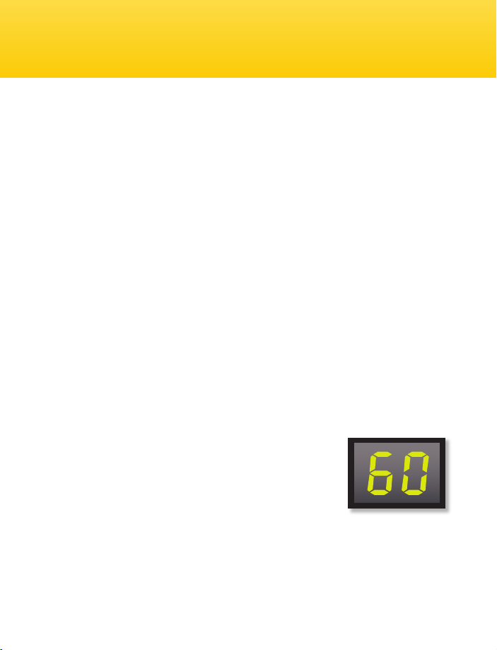
• 100W modeling lamp (60W with VSD-160 model)
• 7˝ grid reector • sync cable
• power cable • user manual
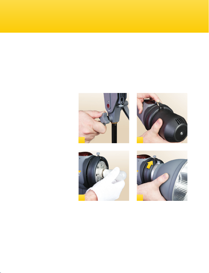
Mount on a stand
(1) Select a stand or support
system of suitable weight
and dimensions to ensure
stable operation of the unit.
Install Reector &
Modeling Lamp
(2) Depress the latch on top
of the monolight, pressing it
toward the back of the unit.
Rotate the protective cap
counter-clockwise. Pull the
cap off and set aside.
(3) Install the modeling
lamp by screwing it into the
threaded socket.
CAUTION: Do not touch the lamp with your bare hands. Oil residue from your ngers can
cause the surface of the lamp to heat unevenly and explode. Use white cotton gloves or a
clean cloth. (4) Install the reector where the protective cap was before. Align the three
pegs on the reector with the three slots, press the reector in and rotate clockwise
until it locks in place.
Note: Take care when tting or removing reectors or softboxes to not damage the
ashtube assembly. The ashtube is very delicate. Always switch off the unit and
disconnect the power before tting or changing lamps, ashtubes, reectors, or softboxes.
Preparing Your Monolight for Use
Page 14 Page 3
10M 25M 50M 75M 100M 10Y 25Y 50Y 75Y 100Y
1
3 4
2
Safety Notes
• Do not use your ash in an environment where moisture
may come in contact with the unit.
• A re hazard exists if ammable materials are placed in close proximity
to the ash tube or the modeling lamp. Do not use your ash
in an environment where ammable vapors are present.
• Do not restrict the ventilation holes when the ash is in use.
• Always switch off the power and disconnect the power cord
before changing the fuse, modeling lamp, or ashtube.
• Avoid placing cables where they can be tripped over.
Replace damaged cords immediately.
• Never use a ash unit with damaged covers, moldings, ashtube,
or modeling lamp. If the unit is dropped or damaged,
have it checked by a professional repair service before using.
• Due to the high-voltage circuitry inside this device,
do not attempt to disassemble or repair the unit yourself.
• Keep out of the reach of children.
Maintenance Notes
• Turn the power off and unplug the power cord when the ash is not in use.
• We recommend charging the ash unit for one to two hours prior to its initial use
and after an extended period of inactivity (more than two weeks).
• If the unit is left unused for a few months, or the unit has been used predominantly
at low power settings, we recommend that the power be increased
to the maximum and the unit left switched on (with the modeling lamp OFF)
occasionally for at least 30 minutes to help preserve the life of the capacitors.
• Avoid rapid, high-power ashing, especially when using restrictive reectors
such as snoots or grids. Excessive heat will shorten the lifespan of your ash unit,
modeling lamp, and ashtube.
Safety and Maintenance Notes