IMS SB-LED User manual

IMS
Nederland
INSTALLATION GUIDE
SB-LED |Indoor
WWW.SB-RAILING.COM
winner

V1.0-2015

3SB-LED | Indoor WWW.SB-RAILING.COM
CONTENTS
1 Introduction 4
1.1 About this guide 4
1.2 Product description 4
1.3 Symbols used in this guide 5
2 Precautions and safety instructions 6
3 Technical specifications 7
3.1 General product specifications 7
3.2 Required tools and products 7
3.3 Main components 8
4 Installation 9
4.1 Preparation for installation 9
4.2 Joining handrail sections 12
4.2.1 Gluing 12
4.2.2 Brazing 13
4.2.3 Expansion joint 14
4.3 Installing the liniLED®LED strip 15
4.4 Fitting handrail brackets or banister adapters 17
4.4.1 Fitting handrail brackets 17
4.4.2 Fitting banister adapters 19
4.5 Finishing 21
4.5.1 Fitting an end cap 21
4.5.2 Fitting a plastic transition profile 22
4.5.3 Fitting the cover cap 22
5 Maintenance 23
6 The environment and disposal 23
7 Warranty and disclaimer 23

4INSTALLATION GUIDE WWW.SB-RAILING.COM
1 INTRODUCTION
1.1 ABOUT THIS GUIDE
This installation guide is intended for installers of SB-LED handrails.
This is the original installation guide, and it contains important information. Please read the installation guide carefully and
completely before installation.
Subject to change without prior notice. Visit www.illunox.com for the latest version of the guide.
1.2 PRODUCT DESCRIPTION
SB-LED handrails can be used as wall-mounted handrails or banisters. The descriptions and instructions
in this guide apply to both types of use.
SB-LED handrails are intended to be used as illuminated stair handrails and banisters for indoor areas. They have built-
in LED lighting to illuminate the floor or ground for the user. Any use other than the use described above is regarded as
improper use. SB-Railing cannot be held responsible for any loss or damage, including consequential loss or damage,
caused by improper use or misuse.
SB-LED is solely intended for indoor use.
Example of indoor application

5SB-LED | Indoor WWW.SB-RAILING.COM
1.3 SYMBOLS USED IN THIS GUIDE
DANGER Danger!
Risk of electrical shock. This symbol means that you should watch out for hazardous situations
that could cause an electrical shock. Failure to follow the safety instructions
can lead to potentially fatal personal injury.
CAUTION Caution!
Risk of damage to the product. “Caution” means that the product may be damaged
if the user does not carefully follow the procedures.
NOTE
Note
This is a comment with supplementary information for the user. A comment draws
the user’s attention to potential problems.

6INSTALLATION GUIDE WWW.SB-RAILING.COM
2 PRECAUTIONS AND
SAFETY INSTRUCTIONS
General
NOTE
The manufacturer considers it extremely important that the product is used and maintained in a
manner that puts the safety of users first. To ensure safety and reliable use, proceed as follows.
Read the installation guide before installing the product.
Ensure that all people involved in the installation and commissioning of the product are
familiar with the relevant information in the installation guide before installation and/or
commissioning of the product takes place. Make sure that the instructions are actually
understood. The responsibility for this rests with the installation supervisor or manager.
NOTE
The manufacturer is not liable for any loss or damage resulting from improper installation.
CAUTION It is important to have the product installed by a certified installer. Otherwise the product warranty
is rendered null and void.
CAUTION Compliance with the installation instructions also means that general and local building, safety
and installation regulations must be respected and followed. The manufacturer
is not liable for failure to comply with these regulations.
Installation
DANGER Always switch off power to the product before performing any work.
DANGER
Never connect the product directly to 220V or 230V power.
NOTE
A voltage of 24V is present in the product or components of the product when connected
to a power source.
CAUTION For electrical connection, always use a 24V power supply with a power rating suitable
for the application.

7SB-LED | Indoor WWW.SB-RAILING.COM
3 TECHNICAL SPECIFICATIONS
3.1 GENERAL PRODUCT SPECIFICATIONS
Product description
Name: SB-LED | Indoor
Launch year: 2015
Type number: ILL422015
Technical specifications
Handrail dimensions: 42.4mm , 40x40mm or 60x40mm
Handrail material: AISI 304 or AISI 316
Material of profile section in handrail: Aluminum 6060-T6
Supply voltage for liniLED strip: 24VDC
LED system protection rating: IP40 (normal indoor use)
Accessories: Various components. See section3.3 for an overview.
3.2 REQUIRED TOOLS AND PRODUCTS
Standard hand tools and metalworking tools should be available on site, depending on the specific project.
The following tools and products are necessary in all cases.
Hacksaw
Grinder
Allen wrenches (3, 4 and 5mm)
Torx 20 screwdriver
No.2 and no.3 screwdrivers
Wire cutter/stripper
Anaerobic adhesive suitable for stainless steel
Degreaser
Brazing equipment (for brazing work on site)
SB-LED LED roller
LED strip nipper

8INSTALLATION GUIDE WWW.SB-RAILING.COM
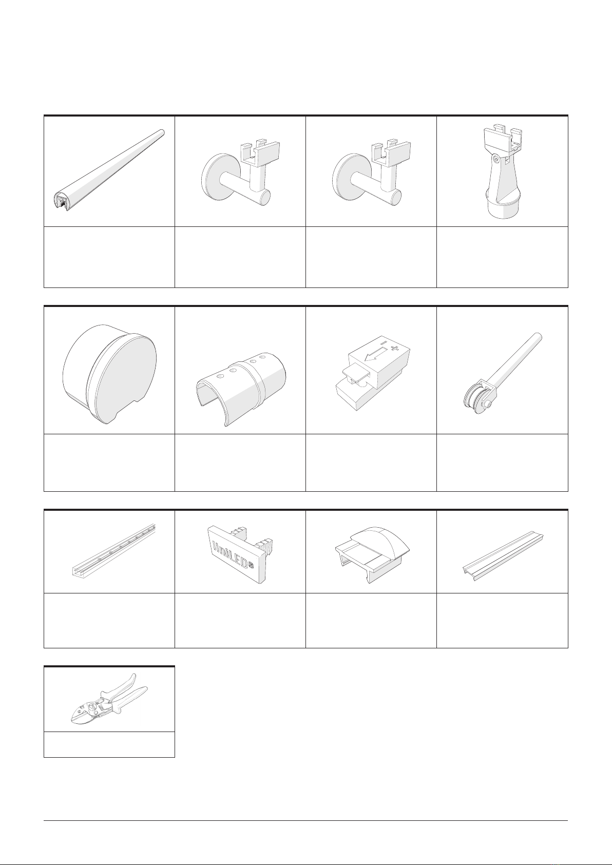
3.3 MAIN COMPONENTS
1 2 3 4
Name: SB-LED Handrail 42
Material: Stainless steel and
6060-T6 aluminum
Item no. 7642.100.304 AISI 304
Item no. 7642.101.316 AISI 316
Name: Stainless steel handrail
bracket, regular 42
Material: Stainless steel
Item no. 7642.200.316 AISI 316
Name: Stainless steel handrail
bracket, wire feedthrough 42
Material: Stainless steel
Item no. 7642.210.316 AISI 316
Name: Stainless steel banister
adapter 42
Material: Stainless steel
Item no. 7642.300.16 AISI 316
5 6 7 8
Name: Stainless steel end cap
42
Material: Stainless steel
Item no. 7642.400.316 AISI 316
Name: Stainless steel profile
handrail connector, straight
Material: Stainless steel
Item no. 7642.500.304 AISI 304
Item no. 7642.501.316 AISI 316
Name: IP40 connector
Material: PA6
Item no. 7642.800.000
Name: SB-LED LED roller
Material: Aluminum and POM
Item no. 7699.101.000
910 11 12
Name: liniLED®LED strip
- liniLED®Top Deco
- liniLED®Top Power
- liniLED®Top Power Short Pitch
Name: IliniLED® Top End Cap
Material: PC-ABS
Item no. 7611.503.000
Name: Plastic transition profile
for SB-LED to round tube 42.4mm
Material: ABS
Item no. 7642.950.424
Name: Plastic cover cap 42
Material: PC
Item no. 7642.900.424 transp.
Item no. 7642.920.424 matte
13
Name: liniLED®Pliers
Item no. 7699.102.000

9SB-LED | Indoor WWW.SB-RAILING.COM
4 INSTALLATION
DANGER Always switch off power before the start of installation.
The instructions in this section are written in the correct installation sequence. We recommend that you follow this
sequence.
4.1 PREPARATION FOR INSTALLATION
1Check that there are enough power points and they
are located in the right places.
Deco: a power point every 20 meters
Power: a power point every 10 meters
Power Short Pitch (PSP): a power point every
10 meters
NOTE
All power points must
provide 24V DC.
24V DC
24V DC
24V DC
2
NOTE
When fitting long sections, take
into account any expansion joints in the structure,
building or surface to which the handrail or banister is
fastened.
Determine whether any expansion joints are present
in the wall or the underlying surface.
To avoid stress on the liniLED® LED strip and
possible damage, the handrail must end
where an expansion joint is present.

10 INSTALLATION GUIDE WWW.SB-RAILING.COM
3Cut the stainless steel handrail to the right length.
If you are joining three or more handrail sections,
you have intermediate handrail sections.
Go to step4.
If you do not have any intermediate handrail sections,
skip step4 and go to section4.2.
Intermediate handrail section
4To allow handrail brackets to be fitted in the profile
later on, you have to make room for them in the
intermediate handrail section.
NOTE
It is not possible to clip a handrail
bracket here later on, since the aluminum profile is
missing at this point.
Carry out the following procedure for EVERY
intermediate handrail section.
A. Dismount one of the screwed-on aluminium
mounting profiles. To do this, turn the screws of
one aluminum mounting profile counterclockwise
and then remove the mounting profile.

11SB-LED | Indoor WWW.SB-RAILING.COM
B. Cut off a length of 40mm (±1mm) from the
removed aluminum profile.
40 mm
NOTE
It is not possible to clip a handrail bracket here later on, since the aluminum profile
is missing at this point.
C. Put the aluminum mounting profile back in place
and screw it tight.
40 mm

12 INSTALLATION GUIDE WWW.SB-RAILING.COM
4.2 JOINING HANDRAIL SECTIONS
There are two ways to join handrail sections:
with glue or by brazing them together.
4.2.1 Gluing
1Apply the glue to the contact surfaces of
the coupling.
2Insert the handrail coupling into the handrail
you want to extend.
3Then slide the other handrail section over
the coupling.
If expansion joints are present,
go to section 4.2.3.
If no expansion joints are present,
go to section 4.3.1.

13SB-LED | Indoor WWW.SB-RAILING.COM
4.2.2 Brazing
1Insert the handrail coupling into the handrail
you want to extend.
2Then slide the other handrail section over
the coupling.
3Braze the parts together.
If expansion joints are present,
go to section 4.2.3.
If no expansion joints are present,
go to section 4.3.1.

14 INSTALLATION GUIDE WWW.SB-RAILING.COM
4.2.3 Expansion joint
Always take the following precaution with an expansion joint to avoid damage to the liniLED® LED strip. This applies to
both glued and brazed handrails.
The handrail can be joined using a coupling with one loose joint (steps1 and2), or it can be terminated with an end
cap (step3). Regardless of whether the handrail is continuous or is terminated by an end cap, the LED strip must be
interrupted at an expansion joint.
For information about fitting and cutting the LED strip, see section4.3.
Terminating the handrail with a coupling
1Apply glue to one end of the coupling.
Fit the coupling for the stainless steel handrail
between two handrail sections.
2Ensure that there is enough free play between
the handrail and the coupling to allow for expansion
and contraction due to temperature changes in the
building structure.
Finishing the handrail with end caps
3Insert the end caps in the ends of
the handrail sections.

15SB-LED | Indoor WWW.SB-RAILING.COM
4.3 INSTALLING THE liniLED®LED STRIP
1Carefully push the connector into the cavity of the
liniLED® LED strip.
NOTE
The arrow on the connector must point
in the same direction as the arrow on the liniLED® LED strip.
2Carefully press the liniLED® LED strip into the
aluminum profile.
Start at the point where you placed the connector.
Tip: Use the SB-LED LED roller.
NOTE
There is a limit to the length of
the liniLED® LED strip that can fitted in one piece.
Deco: 20 meters
Power: 10 meters
Power Short Pitch (PSP): 10 meters
For any of the following situations.
You arrive at a corner
You arrive at a coupling
You arrive at an expansion joint
You reach the end of the handrail
Proceed as follows.
3Determine where you will cut the liniLED® LED strip.
This should be done as close as possible to the
end of the coupling or the end of the handrail.
Note that the liniLED can only be cut at specific designated
places.
NOTE
For more information about liniLED®
Top LED strips, visit www.liniLED.com.
+24V +24V
+
+
liniLED® Top Deco
liniLED® Top Power
(Power version only available
in white)
liniLED® Top Power
(Only applies to the following
colors: red,
green, blue and amber)
liniLED® Top PSP

16 INSTALLATION GUIDE WWW.SB-RAILING.COM
4Cut the liniLED® LED strip.
5Insert an end plug in the cavity of the liniLED® LED
strip and press the end of the LED strip
into the aluminum mounting profile.
Do you have other handrails where you want to install liniLED® LED strip?
6Repeat steps 1 to 5.

17SB-LED | Indoor WWW.SB-RAILING.COM
4.4 FITTING HANDRAIL BRACKETS OR
BANISTER ADAPTERS
4.4.1 Fitting handrail brackets
1Dismantle the handrail bracket.
To do this, use a 5mm allen wrench to loosen
the socket-head screw of the handrail bracket.
2Remove the clip from the handrail bracket.
3Slide the clip of the handrail bracket over the
aluminum profile. You can do this at the end
of the handrail or at the previously made cutout. Slide
the clip to the desired position.

18 INSTALLATION GUIDE WWW.SB-RAILING.COM
Are you fitting a handrail bracket for wire feedthrough?
If yes, go to step4. If no, skip step4.
4First pull the wires through the clip, and then pull
them through the hollow sections of the handrail
bracket.
5Using a 5mm allen wrench, turn the socket-head
screw of the handrail bracket clockwise to secure the
bracket on the aluminum profile.
24VDC
24VDC
24VDC

19SB-LED | Indoor WWW.SB-RAILING.COM
4.4.2 Fitting banister adapters
11. Using a 3mm allen wrench, release the socket-
head screws by turning them counter-clockwise.
2. Remove the clip from the banister adapter.
2
1
2
1
2Slide the clip of the handrail bracket over the
aluminum profile. You can do this at the end of
the handrail or at the previously made cutout. Slide
the clip to the desired position.
Is the banister adapter for feedthrough to your power point?
If yes, go to step3. If no, go to step4.

20 INSTALLATION GUIDE WWW.SB-RAILING.COM
3In this case, first pull the wires through the clip and
then through the banister adapter.
4Firmly screw the banister adapter to the clip.
Using a 4mm allen wrench, turn the socket-head
screws in the banister adapter clockwise to secure
the clip.
NOTE
The clip can pivot up to 55° in either
direction. Before tightening the banister adapter, make
sure that it can be positioned
at the correct angle.
5If the SB-LED handrail is mounted at
a angle, rotate the handrail bracket.
To do this, loosen the socket-head screw (1) by
turning it counterclockwise. Rotate the clip (2) and
then retighten the socket-head screw (clockwise).
11
22
24VDC
Table of contents