Inbay 240000-02 Manual

1
© 2018 · acv GmbH · Straßburger Allee 10-12 · 41812 Erkelenz www.inbay.systems
level of difficultySchwierigkeitsgrad
Sachgemäße Installation unter Beachtung dieser Einbauanleitung erfor-
derlich. Achten Sie auf korrekte Anschlüsse. Verlegen Sie die Kabel so, dass
Sie weder geknickt, gequetscht oder beschädigt werden können. Sorgen
Sie dafür, dass sich die Kabel nicht in Gegenständen verfangen können.
Wir können keine Haftung für Schäden übernehmen, welche durch un-
sachgemäße Installation oder Nutzung verursacht wurden. Verwenden Sie
darum ausschließlich das mitgelieferte Montagematerial.
Technische Änderungen vorbehalten, alle Angaben ohne Gewähr.
Das „Qi“ Logo ist Warenzeichen des „Wireless Power Consortium“
An appropriate installation in observance of these operating instructions
is necessary. Please make sure the wiring is arranged so it is not bended
or crimped due to the risk of cable break. Make sure that all connections
are correct. Route the cable away from moving parts, do not allow the
cable to be entangled, pinched or damaged in any way.
We will not be liable for damage due to improper installation or utilization.
Use the specified accessory parts to prevent product failure.
Subject to technical modifications; no responsibility is accepted for the
accuracy of this information.
The “Qi” symbol is a trademark of the “Wireless Power Consortium”
EINBAUANLEITUNG
DINSTALLATION GUIDE
GB
gering hoch low high
www.inbay.systems
v23102018
Wireless Charging Tray
inbay kit
240000-02
Kit Content
(1) Ladespule (L x B x H): 61 x 55 x 8 mm
(2) Spannungswandler 12V -> 5V / 3A
(3) 1m USB Kabel
(4) Lichtwellenleiter L=19,1 mm / d=2,8 mm
(5) Inbay® Pad Ø = 55 mm
(6) Linsenkopfschraube
(7) Scheibe 2,7 PA6
(8) Abzweigverbinder
(9) Flachstecker
Kit Content
(1) Copper inductor (L x W x H): 61 x 55 x 8 mm
(2) Voltage Transformer 12V -> 5V / 3A
(3) 1m USB cable
(4) Optical waveguide L=19,1 mm / d=2,8 mm
(5) Inbay® Pad Ø = 55 mm
(6) Fillister head screw
(7) Washer 2,7 PA6
(8) Branch Connectors
(9) Blate Terminals
1
2
3
4
5
67
89
Einbauanleitung / Install Manual
2
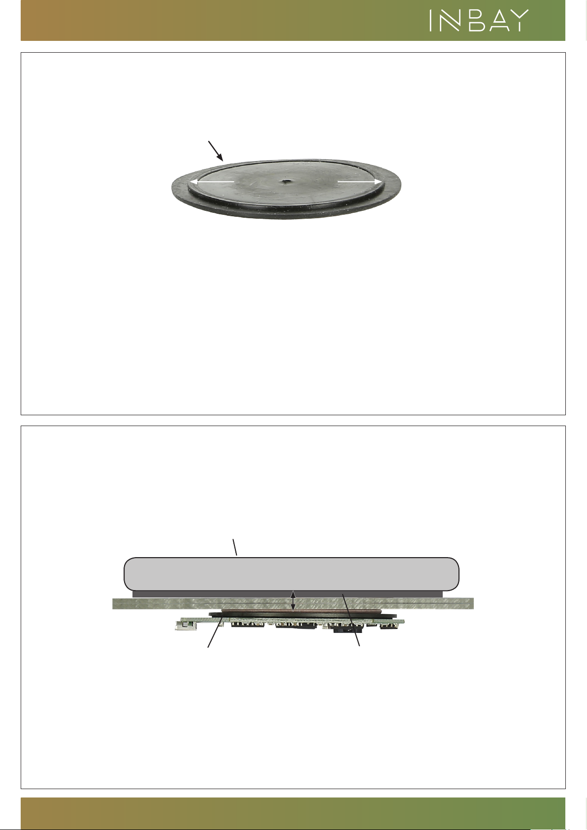
Bohren Sie ein Loch mit einem Durchmesser
von Ø 51 mm in die Oberfläche.
Auf derUnterseite des Inbay® Pads befindet sich
eine entsprechend große Kante, welche in
die Bohrung eingesetzt werden muss um
das Inbay® Pad plan auf der Oberfläche
verkleben zu können.
Mittels des beigefügten Lichtleiters können Sie die
optische Ladestandsanzeige (rotes oder blaues Leuchten)
der Platine auf die Oberfläche des Einbauortes verlegen.
Hierzu muss die abgeflachte Seite des Lichtleiters parallel
zur LED eingebaut werden. Für die Montage des Lichtlei-
ters wird eine Bohrung mit einem Durchmesser von d=2,9
mm benötigt
Der Abstand zwischen Receiver
und Spule muss zwischen 3 - 8 mm betragen.
Idealabstand zwischen Receiver und Spule: 5 mm
Achtung! Der Mindestabstand von 3mm
darf nicht unterschritten werden !!!
Make a hole with a diameter of Ø 51 mm
into the surface.
On the bottom side of the Inbay® Pad is
an edge which has to be inserted into to
hole in order to glue the Inbay® Pad even
to the surface
Make a hole with a diameter of Ø 51 mm
into the surface.
On the bottom side of the inbay Pad is
an edge which has to be inserted into to
hole in order to glue the inbay Pad even
to the surface
The distance between receiver
and cupper inductor must be between 3 - 8 mm.
Ideal distance between receiver and cupper inductor: 5 mm
Caution! There is a minimum distance of 3mm
which must not be undercut !!!
Unterseite des inbay Pads
bottom of inbay pad
Kante / Edge
51 mm
Spule / spool inbay Pad (Antirutschmatte)
inbay pad (anti-skid mat)
Smartphone
Abstand zwischen Spule und Qi-Receiver / Distance between spool and Qi receiver
min: 3 mm - ideal: 5 mm - max: 8 mm / min: 3 mm - ideal: 5 mm - max 8 mm

www.inbay.systems
3
+ 12V
- GND
!
POLARITY ?
Ziehen Sie den Stecker der Bordsteckdose ab
und schieben Sie die Isolierung etwas zurück.
Montieren Sie die Abzweigverbinder auf den
beiden Kabeladern. Verwenden Sie abhängig
von der Kabelstärke die entsprechenden
Abzweigverbinder:
Kabelstärke 2,5mm² blau / Kabelstärke 1,5mm² rot
Achtung - überprüfen Sie vor Anschluss des
Spannungswandlers unbedingt die richtge
Polarität mit einem Voltmeter!
Anschlusskabel des Spannungswandlers:
rot: +12V / schwarz: Masse
Disconnect the plug of the on-board socket and push
down a bit the cable insulation. Mount the branch connec-
tors on both cable wires. Depending on the cable diameter
use the appropriate branch connectors:
Cable diameter 2,5mm² blue / Cable diameter 1,5mm² red
Caution! - check the correct polarity with a voltmeter
before you connect the USB voltage transformer
Connection cables of the USB voltage transformer:
red: +12V / black: ground
USB-Spannungswandler
Montieren Sie den USB-Spannungswandler
an geeigneter Stelle ( dieser kann sichtbar- oder
unsichtbar montiert werden )
Stecken Sie das USB-Anschlusskabel in den
externen Spannungswandler. Sichern Sie die
Steckverbindung gegebenenfalls mit Isolierband.
USB-Voltage-Transformer
Mount the USB voltage transformer at a
suitable place ( the USB voltage transformer
can be installed visible or invisible ).
Plug the USB connection cable into the USB
socket of the USB voltage transformer
If neccessary secure the USB connection cable
with duct tape.
Ø 1,5mm² (rot / red) Ø 2,5mm² (blau / blue)

Einbauanleitung / Install Manual
4
!

Einbauanleitung / Install Manual
CARD
xxxx xxxx xxx
!
NO METAL OBJECTS - CAUTION HOT! - up to 55°C
CAUTION!
Don‘t place any other objects such as coins,
credit cards etc. onto the INBAY surface. Especially
smartphones with attached ring stand holder should
not be used!
ACHTUNG!
Legen Sie keine anderen Gegenstände
wie z.B. Münzen, Kreditkarten etc. in die INBAY
Ablage. Insbesondere Smartphones mit ange-
brachtem Ring Ständer dürfen nicht verwendet
werden!

Einbauanleitung / Install Manual
+12V
5A / 60W max
MANUAL
ACHTUNG! Nach der Installation düfen keine Geräte/Verbraucher mit mehr als 5A / 60W
an der +12V Buchse betrieben werden, da sonst die Gefahr einer Überspannung besteht!
ATTENTION! After installation, devices/consumers with more than 5A / 60W shall not be
operated on the +12V socket. Otherwise a risk of overvoltage can occur!
WICHTIG! NACH DER INSTALLATION MUSS DIESE EINBAUANLEITUNG
IN DAS HANDSCHUHFACH DES KUNDENFAHRZEUGS GELEGT WERDEN.
IMPORTANT! AFTER INSTALLATION THE MANUAL HAS TO BE PLACED INTO
THE DASH BOARD OF THE CUSTOMER‘S CAR.
!

Einbauanleitung / Install Manual

Einbauanleitung / Install Manual
Other Inbay Batteries Charger manuals


