IndeeLift HFL-500-E User manual

HFL-500-E / HFL-600-E
USER’S MANUAL
“From the Ground to the Gurney!”
Lift and Transport
INDEELIFT INC.
5143 Tesla Road
Livermore, CA 94550 USA
844-700-5438
www.indeelift. com

HFL-500-E/HFL-600-E User’s Manual
Page 2of 24
IL-HFL-500/600-E UM
Copyright 2022 IndeeLift Inc. All Rights Reserved
04/07/2022
Please read this entire manual before using the product and retain for future
reference.
TABLE OF CONTENTS
HFL-500-E / HFL- 600-E
Introduction . . . . . . . . . . . . . . . . . . . . . . . . . . . . . . . . . . . . . . . . . . . . . . . . . . . . . . . . . . . . . . . . . . . . . 3
Overview . . . . . . . . . . . . . . . . . . . . . . . . . . . . . . . . . . . . . . . . . . . . . . . . . . . . . . . . . . . . . . . . . . . . . . . . 3
Features/Functionality . . . . . . . . . . . . . . . . . . . . . . . . . . . . . . . . . . . . . . . . . . . . . . . . . . . . . . . . . . . . . 4
Component Identification . . . . . . . . . . . . . . . . . . . . . . . . . . . . . . . . . . . . . . . . . . . . . . . . . . . . . . . . . . 5
Preparing the HFL for use . . . . . . . . . . . . . . . . . . . . . . . . . . . . . . . . . . . . . . . . . . . . . . . . . . . . . . . . . . 6
Operation . . . . . . . . . . . . . . . . . . . . . . . . . . . . . . . . . . . . . . . . . . . . . . . . . . . . . . . . . . . . . . . . . . . . . . . 7
Deploying the HFL . . . . . . . . . . . . . . . . . . . . . . . . . . . . . . . . . . . . . . . . . . . . . . . . . . . . . . . . . . . . . . 7
Belt Assemblies . . . . . . . . . . . . . . . . . . . . . . . . . . . . . . . . . . . . . . . . . . . . . . . . . . . . . . . . . . . . . . . . 8
Standard Lift Procedure . . . . . . . . . . . . . . . . . . . . . . . . . . . . . . . . . . . . . . . . . . . . . . . . . . . . . . . . . 9
Mount Assist Procedure . . . . . . . . . . . . . . . . . . . . . . . . . . . . . . . . . . . . . . . . . . . . . . . . . . . . . . . . . 10
Patient Transport Procedure . . . . . . . . . . . . . . . . . . . . . . . . . . . . . . . . . . . . . . . . . . . . . . . . . . . . . 12
Backboard Lift Procedure . . . . . . . . . . . . . . . . . . . . . . . . . . . . . . . . . . . . . . . . . . . . . . . . . . . . . . . . 13
Optional Stair Handle Set Accessory . . . . . . . . . . . . . . . . . . . . . . . . . . . . . . . . . . . . . . . . . . . . . . . 15
Optional IndeeChuck Patient Maneuvering Tool Procedure . . . . . . . . . . . . . . . . . . . . . . . . . . . 20
Optional Stair Track Accessory . . . . . . . . . . . . . . . . . . . . . . . . . . . . . . . . . . . . . . . . . . . . . . . . . . . 22
Maintenance . . . . . . . . . . . . . . . . . . . . . . . . . . . . . . . . . . . . . . . . . . . . . . . . . . . . . . . . . . . . . . . . . . . . . 23
Troubleshooting/Service . . . . . . . . . . . . . . . . . . . . . . . . . . . . . . . . . . . . . . . . . . . . . . . . . . . . . . . . . . . 23
Warranty Information . . . . . . . . . . . . . . . . . . . . . . . . . . . . . . . . . . . . . . . . . . . . . . . . . . . . . . . . . . . . . 23
Specifications . . . . . . . . . . . . . . . . . . . . . . . . . . . . . . . . . . . . . . . . . . . . . . . . . . . . . . . . . . . . . . . . . . . . 24

HFL-500-E/HFL-600-E User’s Manual
Page 3of 24
IL-HFL-500/600-E UM
Copyright 2022 IndeeLift Inc. All Rights Reserved
04/07/2022
Introduction:
IndeeLift’s patented line of Human Floor Lifts (HFLs) are a class of human lifts unlike any other. This family
of products has been designed to lift individuals who are on the floor or ground and are unable to get up
without assistance. The rugged and reliable IndeeLift HFLs are purpose-built appliances, built in the USA
and are available in home, professional/commercial and emergency medical services (EMS) models.
HFLs for EMS are industrial grade tools designed for emergency responders. These tools were developed
to safely lift and transport patients. They lift a patient from the floor, seated or on a backboard, without
causing injury to either the emergency services personnel or the patient. As a fall recovery appliance, the
HFLs are extremely maneuverable. The small footprint allows fall recovery to occur in much smaller
spaces than other mechanical lift devices. These tools eliminate manual lifting of patients from the floor
on medical-emergency and lift-assist calls. Additionally, the HFLs for EMS are designed to transport the
patient from the incident site to the gurney when required.
Overview:
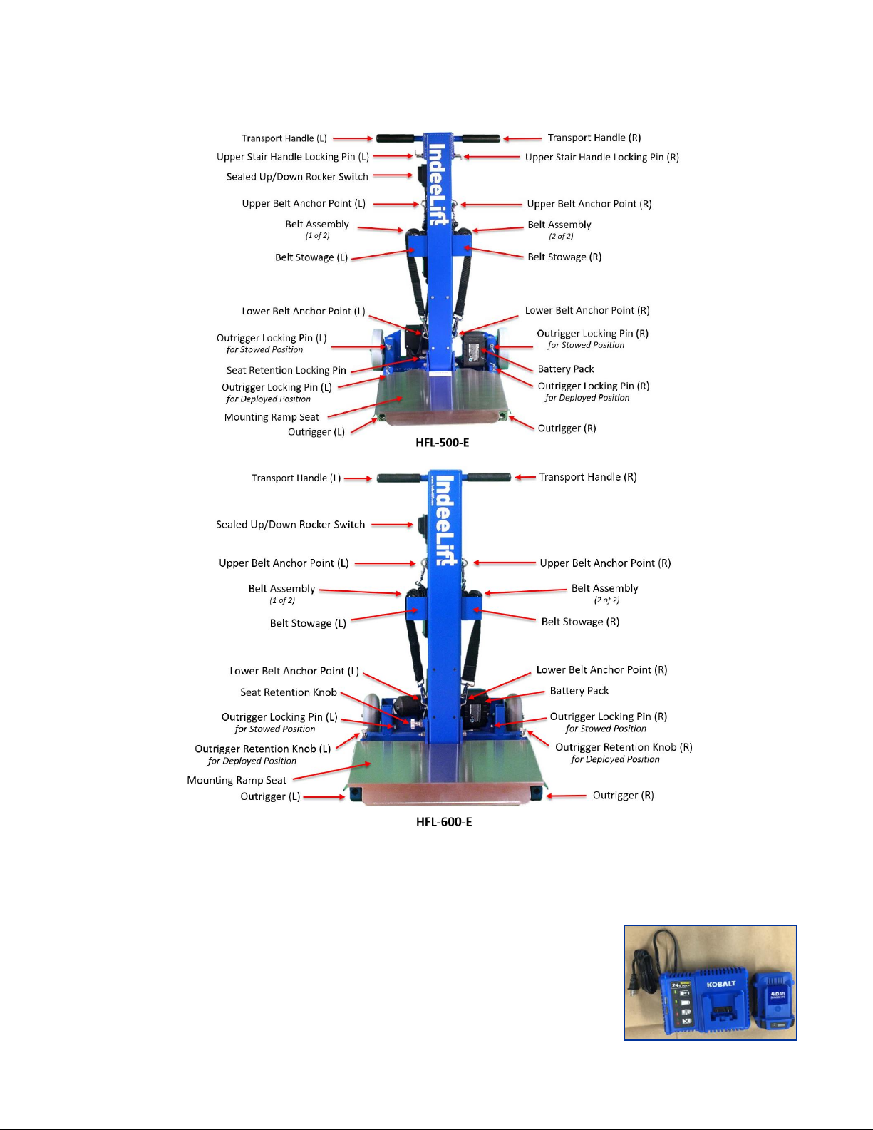
This manual covers both the HFL-500/600-E for emergency medical services. The HFL-500-E is the standard
EMS model and is engineered to lift a person of up to 500 lbs. or 227 kg from the floor. The HFL-600-E is
the bariatric model and is engineered to lift a person of up to 600 lbs. or 272 kg from the floor. Both models
have the same basic features and functions, (any differences are noted in this manual).
The operating mechanism is a linear actuator powered by a 24V DC rechargeable battery pack which is
charged from any standard AC wall outlet using the included battery charger. The device is designed in a
portable “roll-around” configuration utilizing six inch all-terrain wheels and is operated using a sealed and
simple up/down rocker switch.
IndeeLift’s HFL-500/600-E are designed for EMS personnel, (including firefighters, paramedics, public
servants and security personnel). These rugged, state-of-the-art products were developed specifically to
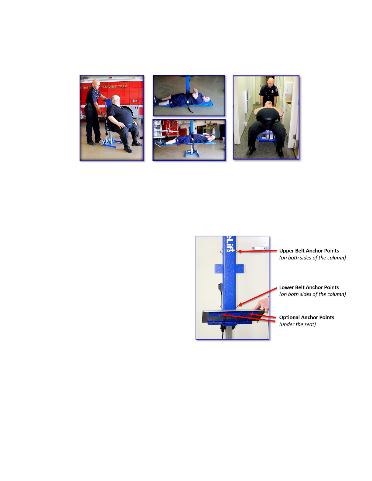
eliminate lift-related injuries to first responders and their fallen patients. Once up from the floor, the
patient can take a deep breath and rest comfortably until they are ready to stand up and walk away, or
they can easily be transported and transferred to a gurney. Alternately, the patient can be lifted on a
backboard then transferred directly to a gurney, without any bending, stooping over, or manual lifting by
the provider.
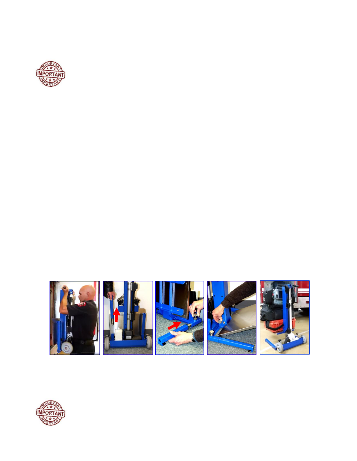
HFL-500/600-Es also double as a dolly for equipment transport, and can be used to transport the patient
to a waiting gurney. The optional Stair Handle Set quickly assembles and deploys when needed, allowing
emergency responders the additional flexibility of maneuvering patients already secured to the HFL up
and down stairs or through uneven terrain or obstructions. The optional IndeeChuck Patient
Maneuvering Tool makes it easy to recover a patient from even the tightest of spaces, where they can
safely be moved to a more open space, positioned on the IndeeLift, and raised from the floor.
Additionally, the optional Stair Tread Accessory for the HFL-500-E makes it easy to transport patients
down stairs while secured to the lift.
Simply put, IndeeLift is revolutionizing emergency medical-assist calls involving patient lifts by doing the
heavy lifting …without risk of injury to the first responders or their patients!

HFL-500-E/HFL-600-E User’s Manual
Page 4of 24
IL-HFL-500/600-E UM
Copyright 2022 IndeeLift Inc. All Rights Reserved
04/07/2022
HFL Features/Functionality:
The HFLs for EMS are designed to lift patients from the ground or floor without the risk of injury
associated with manual lifting. Once the patient is properly positioned on the HFL’s seat, the first
responder presses upward on the sealed up/down rocker switch which engages the linear actuator. In
approximately one minute, the patient is safely raised to a height of 21 inches. The raised-seat height
was designed to allow the patient to stand with minimal effort after being raised from the floor in a
seated position or transfer to any ADA compliant bed, wheelchair or scooter.
Small Footprint and Easy Portability
HFLs for EMS are portable lifts that are rolled around on wheels like a traditional dolly. Their small
footprint allows them to access many places gurneys and other lifts simply cannot go. With a turning
radius of 24” for the HFL-500-E, and 30”for the HFL-600-E, these HFLs can go operate in the tightest of
spaces, including most small bathrooms.
Mounting Ramp Seat
The HFL patent-pending design includes a mounting ramp seat that eliminates the need to manually "lift"
a patient. With no complex cradles or harnesses to configure, the HFL allows fall recovery to be simple
and quick. A person who has fallen can easily slide onto the mounting ramp seat and be off the floor in a
normal seated position within one minute.
Sealed Up/Down Rocker Switch
HFLs for EMS incorporate a sealed up/down rocker switch to operate the lift. The potted enclosure
protects the switch from moisture and contamination.
Rechargeable Battery
The HFLs for EMS come standard with two Kobalt rechargeable Lithium-ION battery packs and a charger.
Each charge is good for approximately 30 lifts. (Replacements available at all Lowes.)
Folding/Stowable Design
Both HFLs for EMS feature stowable outriggers and a folding seat, making them ideal for stowing on
emergency services apparatus. The stowed dimensions for the HFL-500-E are 8” D x 20” W x 33” H and
the stowed dimensions for the HFL-600-E are 12” D x 22” W x 36” allowing the HFLs to be stowed in
multiple locations on most apparatus.

HFL-500-E/HFL-600-E User’s Manual
Page 5of 24
IL-HFL-500/600-E UM
Copyright 2022 IndeeLift Inc. All Rights Reserved
04/07/2022
HFL-500-E/HFL-600-E Component Identification:
Controls: Up/Down Rocker Switch
The Sealed Up/Down Rocker Switch is used to raise and lower the seat. Pressing the rocker switch
towards the top of the unit raises the seat, and pressing the rocker switch towards the bottom of the unit
lowers the seat. Raising or lowering the seat takes approximately 60 seconds.
Batteries and Charger:
Kobalt 24-Volt 4 Amp-Hour Lithium Battery and Charger. NOTE: Batteries
have a power indicator to show how much power remains in the battery.

HFL-500-E/HFL-600-E User’s Manual
Page 6of 24
IL-HFL-500/600-E UM
Copyright 2022 IndeeLift Inc. All Rights Reserved
04/07/2022
Preparing the HFL for use:
Unpacking the HFL:
The HFL comes packaged for shipment in a carton. Packed inside a box in the shipping carton will be the
battery charger, two batteries and two sets of safety belt assemblies.
1) Remove the box cap and sides.
2) Roll the unit onto the floor.
3) Deploy the outriggers and seat as described in Steps 1 - 4 on page 7.
4) Install the battery pack as described in Step 5, below.
5) Test the unit by raising and lowering the seat using the up/down rocker switch.
Charging the Battery Pack
It is recommended that the HFL’s battery pack be fully charged prior to its first use in
the field.
1. Attach the male end of the charger power supply’s input power cord to any standard 110/120 VAC
grounded wall power outlet.
2. Remove the battery pack from the HFL by pressing inward on the two black push-button retention
releases while lifting the battery pack from the device.
3. Place the battery pack in the charger and allow approximately one hour for the battery to fully
charge. Note: The battery pack, charger and the HFL are all keyed so the battery pack cannot be
installed into the charger or the HFL incorrectly.
4. After approximately one hour, remove the battery pack from the charger. NOTE: The LED indicator
glows green when the battery is fully charged.
5. Install the battery into the HFL, ensuring the retention releases snap the battery into place.
NOTE: HFL-500/600-E machines are shipped with two batteries and a charger. This enables the HFL’s
battery to be swapped out at weekly intervals, or as described in the department’s standard
operating procedure for portable tools that utilize rechargeable batteries.

HFL-500-E/HFL-600-E User’s Manual
Page 7of 24
IL-HFL-500/600-E UM
Copyright 2022 IndeeLift Inc. All Rights Reserved
04/07/2022
Operation:
Practice these procedures several times with a colleague playing the role of a fallen patient.
Ensure that any users are thoroughly familiar with the correct operation of the HFL before
they use it to assist an actual patient.
Deploying the HFL:
1. Remove the HFL from its stowed position on the emergency services apparatus and place it on
the ground.
2. One at a time, remove the two outriggers (left and right) from their vertical stowed position by
grasping them firmly and lifting them upward (as indicated by the red arrow in the below
image). NOTE: The outriggers are held in the stowed position by a spring-ball mechanism
requiring slight pressure to be applied to remove them from or return them to their stowed
position. Always ensure that the outriggers snap back into place when returning them to
their stowed position.
3. One at a time, push the outriggers (left and right) into their operational position until the
spring-loaded retention knob locks. Note: Ensure the black ‘feet’ are facing downward, as
shown in image three, below. Always confirm the outriggers are locked by attempting to pull
them out.
4. With one hand, pull the seat’s spring-loaded retention knob outward while using your other
hand to lower the seat. The spring-loaded retention knob will lock into place when the seat
has been fully lowered. Note: The HFL-500-E’s seat covers the outriggers when lowered to the
operational position.
5. Optional: The HFLs for EMS were designed to be used as a dolly to carry the emergency
responder’s EMS equipment or other cargo as necessary. This is accomplished by loading the
equipment/cargo on the HFL’s seat and using the Up/Down Rocker Switch to raise the seat by
approximately 6-12”for a good balance (see Step 7 on page 10 for more details).
NOTE: Move the unit to the location of the patient by placing one foot on the back of the HFL and slightly
tilting the unit backwards by slowly pulling the handles towards you. The HFL can be pulled or pushed
to the location of the patient. Note: Some manual doors dictate the need to pull the HFL through from
behind.
As you stop at the desired location, ensure there are no foreign objects beneath the
seat before tilting the unit back to the upright (operational) position.

HFL-500-E/HFL-600-E User’s Manual
Page 8of 24
IL-HFL-500/600-E UM
Copyright 2022 IndeeLift Inc. All Rights Reserved
04/07/2022
Belt Assemblies:
The HFL-500-E and 550-E come standard with two safety-belt assemblies which are used to secure the
patient to the lift.
Overview:
The belt assemblies are stowed on the lift when not in use. Each belt assembly includes two straps; the
longer strap has a seatbelt style buckle with a snap hook at the end, the shorter strap has a seatbelt style
clasp with a snap hook at the end. Each of the two straps form a single belt assembly. In use, they are
secured to the HFL’s belt anchor points using the snap hooks at the end of each belt assembly.
Belt Anchor Points:
There are three sets of anchor points on the HFL for
the belt assemblies (six in total). Two sets (upper
and lower) are located on either side of the HFL’s
main column and are the most commonly used.
There are two additional anchor points on the
forward frame underneath the seat which provide
additional strapping options for unique situations,
(e.g., patient’s size, weight or condition).
Standard Belt Configurations:
In many cases, only one of the belt assemblies is required and it is typically secured to the lower anchor
points as a waist belt. This is the normal configuration for a standard patient lift, (where the patient is
able to sit upright by their own control), and the belt is used as a safety precaution while the patient is
being lifted.
Only one belt assembly is needed when lifting a patient secured to a backboard. Using the upper belt
anchor points, route the belt assembly over the patient and loop it through the center handle of the
backboard, (on the opposite side of the HFL), then buckle the seat belt and remove the slack.

HFL-500-E/HFL-600-E User’s Manual
Page 9of 24
IL-HFL-500/600-E UM
Copyright 2022 IndeeLift Inc. All Rights Reserved
04/07/2022
Typically, the upper anchor points are used with the additional belt assembly when needed as a chest
belt. The chest belt is used along with the waist belt when a patient is to be transported on the lift. The
standard use of the belt assemblies as waist belts, chest belts, and for a backboard lift are covered in
more detail in the Operation section of this manual.
Optional Belt Configurations:
While the standard configurations described above will work well for most situations, the IndeeLift HFLs
for EMS have six anchor points which provide emergency responders with many different belt options,
(depending on the circumstances). These options include, but are not limited to, those shown below.
Standard Lift Procedure:
This procedure is used for a standard lift-assist where the patient is conscious and simply needs assistance
being lifted from the floor. NOTE: It is recommended that you view theHFL-600-E training video as you
learn this procedure.
1. Position the HFL directly behind the fallen patient, with the seat positioned as close to the
fallen patient’s buttocks as possible.
2. Have the patient scoot themselves backwards onto the seat, until their back is resting on the
HFL’s vertical frame. NOTE: If the fallen patient has difficulty scooting backwards onto the seat,
use the Mount Assist Procedure starting on page 10.

HFL-500-E/HFL-600-E User’s Manual
Page 10 of 24
IL-HFL-500/600-E UM
Copyright 2022 IndeeLift Inc. All Rights Reserved
04/07/2022
3. Once the patient is fully seated to the rear of the HFL’s seat, ask the patient to lift their arms
slightly and, using one of the belt assemblies as a waist belt (i.e., secured to the lower anchor
points), position the belt around the patient’s waist, buckle the seat belt and remove any slack.
4. Position yourself behind the HFL and ask the patient if they are ready to be lifted. Once they are
ready, press the up/down rocker switch upward and hold the switch in the up position. The seat
will rise for approximately sixty seconds and then stop.
5. Once the lift has stopped, allow the patient to rest if needed, ensure the patient’s feet are
positioned properly for standing, unbuckle the seat belt then offer to assist the patient as they
stand up from the seat, (as they would from any chair).
6. Once the fallen patient has been recovered, return the seat to the fully downward (home)
position before rolling the HFL back to the apparatus. NOTE: Always ensure there are no
foreign objects below the seat before returning it to the home position.
7. If desired, the HFL can be used as a dolly to transport equipment/cargo
or tools back to the emergency apparatus. Load the gear on the HFL
then raise the seat by approximately 6” for proper balance, place one
foot on the stainless-steel footrest on the back of the HFL. Slightly tilt
the unit backwards by slowly pulling the handles towards you. The HFL
can now be pulled or pushed back to the emergency apparatus. Note:
Some manual doors dictate the need to pull the HFL through from
behind.
NOTE: Before stowing the HFL on the apparatus, stow the belt assemblies and return the
HFL to its fully stowed configuration by reversing the procedures for Deploying the HFL on
page 7.
Mount Assist Procedure:
This procedure is used for medical-assist calls and lift-assists where the patient is unable to mount the
device themselves. NOTE: It is recommended that you view the HFL-500-E training video as you learn this
procedure.
1. With the patient laying down on the floor, position the HFL behind them and position the
patient’s legs as far forward as possible, (to form an “L” shape).
2. Adjust the positioning of the HFL to have one edge of the seat as close to the patient’s
buttocks as possible.

HFL-500-E/HFL-600-E User’s Manual
Page 11 of 24
IL-HFL-500/600-E UM
Copyright 2022 IndeeLift Inc. All Rights Reserved
04/07/2022
3. Offer the patient your hand and gently tilt them up to a seated position on the center of the
HFL’s seat. If needed, assist the patient to be positioned in the center of the seat, as far back
on the seat as possible, (so their back is resting on the HFL’s vertical frame).
4. Once the patient is fully seated to the rear of the HFL’s seat, ask the patient to lift their arms
slightly and, using one of the belt assemblies as a waist belt (i.e., secured to the lower
anchor points), position the belt around the patient’s waist, buckle the seat belt and remove
any slack.
5. Position yourself behind the HFL and ask the patient if they are ready to be lifted. Once they
are ready, press the up/down rocker switch upward and hold the switch in the up position.
The seat will rise for approximately sixty seconds and then stop.
6. Once the lift has stopped, allow the patient to rest if needed, ensure the patient’s feet are
positioned properly for standing, unbuckle the seat belt then offer to assist the patient as
they stand up from the seat, (as they would from any chair). NOTE: If the patient requires
transport (e.g., to a waiting gurney), utilize the Patient Transport Procedure starting on
page 12.
7. Once the fallen patient has been recovered, return the seat to the fully downward (home)
position before rolling the HFL back to the fire apparatus. NOTE: Always ensure there are no
foreign objects below the seat before returning it to the home position.
8. If desired, the HFL can be used as a dolly to transport equipment/cargo or tools back to
the emergency apparatus. Load the gear on the HFL then raise the seat by
approximately 6” for proper balance, place one foot on the stainless-steel footrest on
the back of the HFL. Slightly tilt the unit backwards by slowly pulling the handles
towards you. The HFL can now be pulled or pushed to back to the apparatus. Note:
Some manual doors dictate the need to pull the HFL through from behind.
9. Before stowing the HFL on the apparatus, stow the belt assemblies and return the HFL
to its fully stowed configuration by reversing the procedures for Deploying the HFL on
page 7.

HFL-500-E/HFL-600-E User’s Manual
Page 12 of 24
IL-HFL-500/600-E UM
Copyright 2022 IndeeLift Inc. All Rights Reserved
04/07/2022
Patient Transport Procedure:
This procedure is used to secure and transport a patient using the HFL. Once the patient is secured, a
single operator can transport even the largest of patients safely down hallways, around corners and
through doorways that are inaccessible to any gurney. NOTE: It is recommended that you view theHFL-
600-E training video as you learn this procedure.
1. Position the HFL directly behind the fallen patient, with the seat positioned as close to the fallen
patient’s buttocks as possible then have the patient scoot themselves backwards onto the seat,
until their back is resting on the HFL’s vertical frame. NOTE: If the fallen patient has difficulty
scooting backwards onto the seat, use the Mount Assist Procedure starting on page 10.
2. Once the patient is fully seated in the center and to the rear of the HFL’s seat, ask the patient to
lift their arms slightly and, using one of the belt assemblies as a waist belt (i.e., secured to the
lower anchor points), position the belt around the patient’s waist, buckle the seat belt and
remove any slack.
3. With the patient’s arms still raised, use the second belt assembly as a chest belt (i.e., secured to
the upper anchor points) and position the chest belt above the patient’s waist and below their
armpits, buckle the seat belt and remove any slack. NOTE: Typically, the second belt assembly
(i.e., chest belt), is only required when using the HFL to transport a patient that is unable to sit up
under their own power.
4. Ask the patient if they are ready to be lifted. Once they are ready, press the up/down rocker
switch upward and hold the switch in the up position until the seat has raised 10 to 12 inches
from the floor. This allows the weight to be transferred to the wheels. At this point, release the
up/down rocker switch. NOTE: This positioning of the patient achieves a good balance point,
making for a safe and easy roll to the desired location.
5. While standing behind the patient, have them cross their arms and ask if they are ready to be
moved. When they are ready, place one foot on the stainless-steel footrest on the back of the
HFL, firmly grasp the handles, and slowly pull back on the handles to tilt the HFL backwards, just
enough to achieve balance.
6. You can now transport the patient to the desired location. NOTE: You can either transport the
patient by pushing the HFL forward, or pulling the HFL backwards. Recommended procedure is to
push the patient forward while another leads the way and assists by opening doors and ensuring
the path of travel is clear.

HFL-500-E/HFL-600-E User’s Manual
Page 13 of 24
IL-HFL-500/600-E UM
Copyright 2022 IndeeLift Inc. All Rights Reserved
04/07/2022
Patient Transport Procedure (continued):
7. Once arriving at the destination, remain positioned behind the HFL and allow the HFL and the
patient to tilt forward until the patient and the HFL are in the fixed position.
8. Ask the patient if they are ready to be lifted. When they are ready, press the Up/Down Rocker
Switch upward and hold the switch in the up position until it reaches the full height and
automatically stops.
9. Once the lift has stopped, ensure the patient’s feet are positioned properly for standing,
unbuckle both seat belts then offer to assist the patient as they stand up from the seat, (as they
would from any chair). NOTE: If transferring the patient to a gurney, adjust the height of the
gurney to be slightly lower than the height of the HFL’s raised seat, then assist the patient from
the HFL onto the gurney.
10. When done, return the seat to the fully downward (home) position before rolling the HFL back to
the emergency apparatus. NOTE: Always ensure there are no foreign objects below the seat
before returning it to the home position.
11. Before stowing the HFL on the emergency apparatus, stow the belt assemblies and return the
HFL to its stowed configuration by reversing the procedures for Deploying the HFL on page 7.
Backboard Lift Procedure:
This procedure requires at least two participants and is used to lift a patient that has been properly
secured to a backboard for transfer to a gurney without any manual lifting. NOTE: It is recommended that
you view the HFL-600-E training video as you learn this procedure.
1. Position the HFL centered as close to the backboard as possible. This will achieve a proper balance
when lifting the patient secured to the backboard.
2. One participant performs a slight log-roll of the backboard (away from the HFL) as the other
participant positions the HFL’s seat under the backboard.
3. Once the HFL is properly positioned, the two participants log-roll the backboard onto the HFL.

HFL-500-E/HFL-600-E User’s Manual
Page 14 of 24
IL-HFL-500/600-E UM
Copyright 2022 IndeeLift Inc. All Rights Reserved
04/07/2022
4. Deploy one of the belt assemblies, secure it to the upper anchor points, then route the belt over
the patient and loop it through the center handle of the backboard (on the opposite side of the
HFL). Then buckle the seat belt and remove the slack. NOTE: Tighten the safety strap snug to
ensure the patients weight is shifted slightly toward the lift column of the HFL.
5. With the patient and backboard secured on the HFL, ask the patient if they are ready to be lifted.
Once they are ready, press the up/down rocker switch upward and hold the switch in the up
position. The seat will rise for approximately sixty seconds and then stop.
6. You can now move the gurney alongside the raised backboard, (with the gurney’s height slightly
lower than the backboard’s), unbuckle to seat belt and, using two of the emergency responders at
both ends of the backboard, and simply slide the backboard onto the gurney!
NOTES:
•Once the patient and backboard are on the gurney and the patient has been transported as
required, follow the previously described procedures for returning the seat to the fully downward
(home) position before rolling the HFL back to the emergency apparatus. NOTE: Always ensure
there are no foreign objects below the seat before returning it to the home position.
•Before stowing the HFL on the fire emergency apparatus, stow the belt assembly and return the
HFL to its stowed configuration by reversing the procedures for Deploying the HFL on page 7.

HFL-500-E/HFL-600-E User’s Manual
Page 15 of 24
IL-HFL-500/600-E UM
Copyright 2022 IndeeLift Inc. All Rights Reserved
04/07/2022
Optional Stair Handle Set Accessory:
The IndeeLift HFLs for EMS were designed to allow emergency responders to easily transport patients
secured to the HFL on level ground. The optional stair handle set quickly assembles and deploys when
needed, allowing emergency responders the additional flexibility of maneuvering patients already
secured to the HFL up and down stairs or through uneven terrain or obstructions. NOTE: At least two
emergency responders are needed when using the stair handle set.
Overview:
The HFL easily transports patients on level ground. The stair handle set also allows emergency responders
to safely guide the HFL over steps and through rough terrain or obstructions. However, they are not
designed for lifting the HFL off the ground when transporting patients secured to the HFL.
IMPORTANT: When using the stair handle set while transporting a patient, always ensure the wheels of
the HFL bear the majority of the patient’s weight (as covered in this section’s procedures).
Depending on the size and weight of the patient, up to four emergency responders can be used when
transporting a patient using the stair handle set, (with two responders using the upper handles and two
responders using the lower handles to guide the HFL as needed).
NOTE: In an emergency situation, (such as transporting a patient through rough terrain or obstacles
during an evacuation), the stair handle set can be used to lift and carry the HFL off the ground. However,
we do not recommend lifting the HFL off the ground with more than 200 lbs. secured to the lift.
Always follow safe lifting procedures when lifting any weight!

HFL-500-E/HFL-600-E User’s Manual
Page 16 of 24
IL-HFL-500/600-E UM
Copyright 2022 IndeeLift Inc. All Rights Reserved
04/07/2022
When traversing stairs with a patient on the HFL, the emergency responders should determine the best
way to face, based on the actual circumstances, (responders typically face each other when transporting a
patient via stairs). However, when going up stairs, the emergency responder using the upper handles has
the option of facing away from the lift, if they deem that to be more appropriate to the specific situation,
(i.e., so they can look forward in the direction of travel).
Stair Handle Set Components:
There are four components in the stair
handle set; two upper handles (left and
right), and two lower handles (left and
right). Note: The upper handles are longer
than the lower handles, as shown.
Also included is a storage bag that mounts
on the back of the lift’s main column.
NOTE: The Stair Handle Set accessory and
the IndeeChuck accessory can both be
secured to the HFL in their separate storage
bags at the same time.
Mounting Points:
The left and right upper handles are affixed to the HFL in the two round mounting points on the top of the
lift, (they are left/right specific). The lower handles affix directly to the left and right outriggers on the
bottom of the HFL, (they are not left/right specific).
Deploying the Upper Handles:
The upper pair of handles are the longer of the two handle sets with the rubber grips. Install the upper
handles (left & right) by standing behind the lift. NOTE: The upper handles are different for the left and
right sides (as shown in the fifth picture on the next page).
1. Insert the left upper handle into the HFL’s left upper mounting point.
2. Secure it in place using the locking pin on the 500-E’s column, or the lanyard’s locking pin on the
600-E’s left upper handle, (see image two and three on the next page).

HFL-500-E/HFL-600-E User’s Manual
Page 17 of 24
IL-HFL-500/600-E UM
Copyright 2022 IndeeLift Inc. All Rights Reserved
04/07/2022
3. Insert the right upper handle into the HFL’s right upper mounting point,(image four).
4. Secure it in place using the locking pin on the 500-E’s column, or the lanyard’s locking pin on the
600-E’s right upper handle, (image five).
NOTE: Image six shows both upper stair handles in their deployed configuration.
Deploying the Lower Handles:
The lower pair of handles are the shorter of the two handle sets with the rubber grips, and affix directly to
the left and right outriggers on the bottom of the HFL (they are not left/right specific). NOTE: When
transporting a patient on the HFL using the stair handle set, it is recommended that the lower handles be
installed after the patient has been properly secured to the lift. Therefore, to affix the lower handles,
follow the Patient Transport Procedure, steps 1 –5 on page 12, then proceed as follows.
1. Once the patient is properly secured to the lift and balanced for transport, have one emergency
responder stand behind the HFL and tilt the lift backward.
2. Standing in front of the HFL, a second emergency responder installs one of the lower handles
(under spring tension) into one of the outriggers by positioning the handle so it faces away from
the lift. Reminder: The lower handles are not left/right specific.
3. While pushing against the spring tension, the second emergency responder turns the lower
handle downward, (as indicated by the red arrow in the second image below), until it locks into
place.
4. The second emergency responder repeats the above steps for the second lower handle.
5. Once the lower handles are installed, give them a slight tug to ensure they are properly secured.
Column Mounted Lanyard Mounted
Locking Pin (500-E) Locking Pin (600-E)

HFL-500-E/HFL-600-E User’s Manual
Page 18 of 24
IL-HFL-500/600-E UM
Copyright 2022 IndeeLift Inc. All Rights Reserved
04/07/2022
Transporting the HFL Up or Down Stairs Without a Patient:
When the HFL needs to be transported up or down stairs without a patient (e.g., to the location of a fallen
patient), first install the upper and lower handles using the previous steps in this section. NOTE: To
transport the HFL up a stairwell, the emergency responder using the upper handles may choose to face
away from the HFL to allow better visibility of the path of travel (as shown in the second picture below).
IMPORTANT: Once you have arrived at the location of the fallen patient, remove both lower handles
before using the HFL to recover the fallen patient.
Transporting a Patient Down Stairs:
Once the patient has been properly secured to the lift using the waist and chest belt configurations and
has been raised to the proper height for a good balance point (as described previously), they are ready to
be transported down stairs. Using the wheels of the HFL to bear the majority of the weight, both
emergency responders keep their backs straight as they use the stair handles to guide the HFL’s wheels
down each stair step, one-at-a-time (as described in the following procedure).
1. With the patient properly secured and balanced for transport, ask the patient to cross their arms
over their chest and move their feet inward as the emergency responder positioned behind the
lift uses the upper handles to tilt the HFL slightly backward.
2. Another emergency responder installs both lower handles (left & right) into their mounting
position on the outriggers and ensures they are properly secured in place.
3. Both emergency responders coordinate their actions as they position the HFL’s wheels to be
evenly aligned with the first step (at the top of the stairwell).
4. Working together (e.g., saying “one, two, three, … down”), the emergency responder at the
bottom of the HFL uses the lower handles to guide the wheels over the edge of the first step,
allowing the wheels to bear the majority of the weight as they roll off the edge of the first step and
onto the next step.
5. Repeat Step 4 (above) for the remaining stair-steps involved.

HFL-500-E/HFL-600-E User’s Manual
Page 19 of 24
IL-HFL-500/600-E UM
Copyright 2022 IndeeLift Inc. All Rights Reserved
04/07/2022
6. Once the final stair-step has been traversed, the emergency responder using the upper handles
keeps the HFL tilted slightly backward while the emergency responder using the lower handles
removes them from the HFL.
7. When the patient has been successfully transported down
the stairs, the emergency responder behind the patient tilts
the HFL forward into its normal upright position and raises
the HFL’s seat to its full height. The responders ensure the
patient’s feet are properly positioned for standing, then
unbuckle the chest and waist belts and assist the patient as
they stand from the lift or are transferred to a waiting
gurney.
Transporting a Patient Up Stairs:
Once the patient has been properly secured to the lift and has been raised to the proper height for a good
balance (as previously described), the patient is ready to be transported up stairs. Using the wheels to
bear most of the weight, the responders keep their backs straight as they use the stair handles to guide
the HFL’s wheels up each stair step, one-at-a-time.
1. With the patient properly secured and balanced for transport, position the back of the HFL’s
wheels to be evenly aligned with the first step (at the bottom of the stairwell). NOTE: The
emergency responder using the upper handles will be on the stairs behind the patient,
(approximately three to four steps up, as shown below).
2. Ensure the patient’s arms are crossed over their chest and their feet are positioned inward as the
responder positioned behind the HFL on the stairs uses the upper handles to tilt the lift slightly
backward while another emergency responder installs both lower handles (left & right) into their
mounting positions on the outriggers and ensures they are properly secured in place.
3. Both emergency responders position the HFL to where its wheels are contacting the rise of the
first step. The responder at the bottom of the lift properly positions themselves to utilize standard
safe lifting techniques (bending at the knees, lifting with the legs, etc.).
4. The responders verbally coordinate their actions, (e.g., saying “one, two, three, … up”), as they
use the stair handles to apply upward lift while guiding the wheels up the rise and onto the step,
allowing the wheels to bear the majority of the weight as they roll up the edge of the first step and
onto the next step.
5. Repeat Step 4 (above) for the remaining stair-steps involved.

HFL-500-E/HFL-600-E User’s Manual
Page 20 of 24
IL-HFL-500/600-E UM
Copyright 2022 IndeeLift Inc. All Rights Reserved
04/07/2022
6. Once the final stair-step has been traversed, the emergency responder using the upper handles
keeps the HFL tilted slightly backward while the emergency responder using the lower handles
removes them from the HFL.
7. When the patient has been successfully transported up the stairs, the
responder behind the patient tilts the HFL forward into its normal upright
position and raises the HFL’s to its full height. The responders ensure the
patient’s feet are properly positioned for standing, unbuckle the chest and
waist belts and assist the patient as they stand from the lift or are
transferred to a waiting gurney.
Optional “IndeeChuck” Patient Maneuvering Tool Accessory:
“IndeeChuck” Patient Maneuvering Tool Procedure:
This procedure utilizes the optional “IndeeChuck” Patient Maneuvering Tool to retrieve a patient from an
inaccessible area and move them to an accessible area, where they can easily be lifted using the HFL.
Typically, only two emergency responders are required when using this procedure. NOTE: It is
recommended that you view theHFL-600-E training video as you learn this procedure.
1. Position the HFL in an easily accessible location, remove the IndeeChuck from its stored location
on the HFL and proceed to the location of the patient.
2. Unfold and position the IndeeChuck to one side of the patient, then deploy the maneuvering strap
loops (two away from you and two towards you).
3. Assist the patient as they lean away from the IndeeChuck then position it underneath the patient.
4. Have the patient lean to the other side, fully deploy the IndeeChuck, and then assist the patient to
a seated position directly in the center of the IndeeChuck.
5. With one emergency responder behind the patient and the other in front, pick up the
maneuvering straps and slide the patient to the waiting HFL. NOTE: Remain in a fully standing
position while sliding the patient, (to avoid any bending or back strain).
Other manuals for HFL-500-E
1
This manual suits for next models
1
Table of contents
Other IndeeLift Lifting System manuals