Ergoswiss SLA VD Series User manual

Operating Instruction
Spindle lifting system SLA/SLG VD
Doc
ument no.: B-00081
Edition 2019 02
Operating instruction EN
Copyright by Ergoswiss AG
1/20
Operating instruction - Spindle lifting system SLA/SLG VD
It is essential to read this operating instruction thoroughly before commissioning the system.
This operating instruction has to be stored in the immediate vicinity of the system.
Linear unit type SLA or SLG
Control box VD SCT
Manual control switch Up/Down or Memory
Errors and technical changes reserved.
Ergoswiss AG does not assume any liability for operating
errors or using the products outside of the intended
purpose use.
At the time of delivery Ergoswiss AG will replace or re-
pair defect products within accordance with the war-
ranty provisions. In addition, Ergoswiss assumes no
other liability.
For your questions and special custom demand
Ergoswiss AG will be at your disposal.
Ergoswiss AG
Nöllenstrasse 15
CH-9443 Widnau
Tel.: +41 (0) 71 727 06 70
Fax: +41 (0) 71 727 06 79
info@ergoswiss.com
www.ergoswiss.com
2
1
3

Operating Instruction
Spindle lifting system SLA/SLG VD
Doc
ument no.: B-00081
Edition 2019 02
Operating instruction EN
Copyright by Ergoswiss AG
2/20
This operating instruction applies to:
Lifting system SLA
Example: Lifting system SLA 4330 EU 11 (Item number: 903.20033)
Description
Standard version
SLA:
Linear unit type
SLA, SLG
4330:
Number of linear units
1, 2, 3, 4
4330:
Spindle pitch in mm
3 mm
4330:
Stroke length in cm
30, 40 cm
EU
Power cable
EU, CH, IT, UK, US
11
11= manual control switch up/down ; 12= Memory
11, 12 -> (VD)
Lifting system SLG
Example: Lifting system SLG 4330 EU 11 (Item number: 904.20033)
Description
Standard version
SLG:
Linear unit type
SLA, SLG
4330:
Number of linear units
1, 2, 3, 4
4330:
Spindle pitch in mm
3 mm
4330:
Stroke length in cm
30, 40 cm
EU
Power cable
EU, CH, IT, UK, US
11
11= manual control switch up/down ; 12= Memory
11, 12 -> (VD)

Operating Instruction
Spindle lifting system SLA/SLG VD
Doc
ument no.: B-00081
Edition 2019 02
Operating instruction EN
Copyright by Ergoswiss AG
3/20
Table of content
1System description .....................................................................................................................................4
1.1 General................................................................................................................................................4
1.2 Intended purpose use ...........................................................................................................................4
1.3 Target group and prior knowledge .........................................................................................................4
1.4 Performance characteristics ...................................................................................................................5
1.4.1 Linear unit SLA 13xx.........................................................................................................................5
1.4.2 Linear unit SLG 13xx.........................................................................................................................5
1.4.3 Motor SX D30 24 V...........................................................................................................................5
1.4.4 Control box VD SCT2 and SCT4 .........................................................................................................5
1.4.5Manual control switch VD Up / Down and memory ..............................................................................5
2Safety requirements ...................................................................................................................................6
2.1 Explanations of the symbols and notes ...................................................................................................6
2.2 Basic safety instructions ........................................................................................................................7
3Preperation for first initial operation .........................................................................................................8
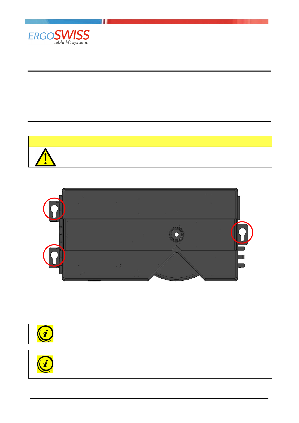
3.1 Mounting the control box and connecting the cables ................................................................................8
3.2 Mounting of the manual control switch ................................................................................................. 10
3.2.1 Manual control switch VD Up / Down ............................................................................................... 10
3.2.2 Manual control switch VD / Memory ................................................................................................. 10
3.2.3 Manual control switch VD Memory T6............................................................................................... 11
4Initial operation ....................................................................................................................................... 12
5Operation ................................................................................................................................................. 13
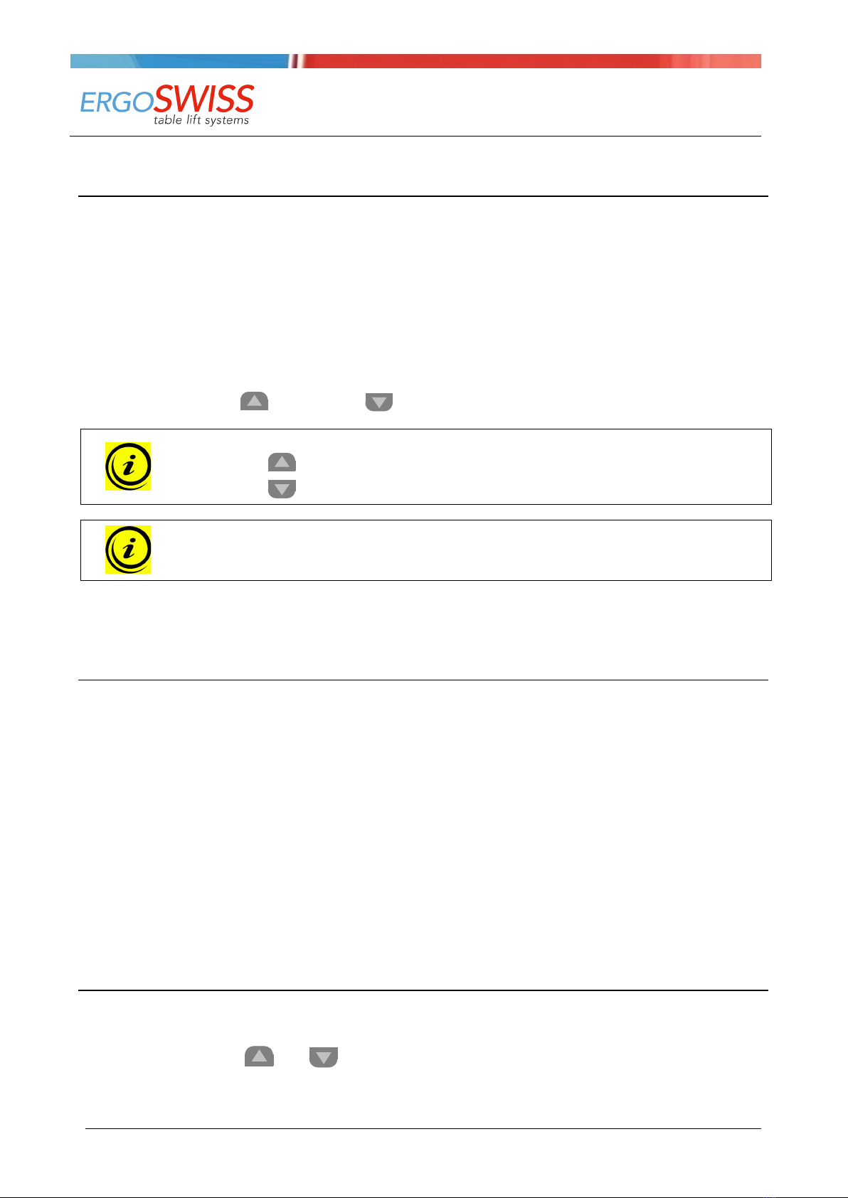
5.1 Drive up / down ................................................................................................................................. 13
5.2 Duty cycle monitoring ......................................................................................................................... 13
5.3 Saving a memory position (Only with manual control switch type Memory!) ............................................. 13
5.4 Approaching a stored position (Only with manual control switch type Memory!) ....................................... 13
5.5 Container-Stop and Shelf-Stop-positions (Only with manual control switch type Memory!)......................... 14
5.5.1 Child-proof lock (Only with manual control switch type Memory!) ....................................................... 14
5.6 Reset of the control box ...................................................................................................................... 14
6Synchronous operation of 2 control boxes ............................................................................................. 15
6.1 Cable connections............................................................................................................................... 15
6.2 Commissioning the synchronized system............................................................................................... 15
7Safety strip - Squeezing protection......................................................................................................... 16
7.1 Technical Data ................................................................................................................................... 16
8Maintenance and disposal ....................................................................................................................... 17
8.1 Maintenance and cleaning ................................................................................................................... 17
8.2 Repairs and spare parts ...................................................................................................................... 17
8.3 Disassembly and disposal .................................................................................................................... 17
8.4 Electrical and Electronic Equipment Act................................................................................................. 17
8.5 Error messages on the display (Only with manual control switch type Memory!)....................................... 18
8.6 Trouble-shooting ................................................................................................................................ 19
9Declaration of Incorporation ................................................................................................................... 20

Operating Instruction
Spindle lifting system SLA/SLG VD
Doc
ument no.: B-00081
Edition 2019 02
Operating instruction EN
Copyright by Ergoswiss AG
4/20
1System description
1.1 General
The basic functionality of a spindle lifting system SLA/SLG by Ergoswiss AG is the lifting and lowering of
work surfaces, machine parts, profile systems, etc.
An operative spindle lifting System SLA/SLG consists of a minimum of following components:
•Linear unit (with integrated spindle drive)
•Control unit (control box, manual control switch and power cable)
The housing of the linear unit SLA/SLG is made out of a colorless anodized aluminium profile. The steel pis-
ton pipe is guided in a plastic bushing and is moved by an inline spindle drive. Up to 4 linear units can be
connected to one control box VD SCT4 and be operated synchronously.
The high-performance control box VD SCT is equipped with two or four motor channels, which are adjusted
synchronously by an encoder converter. Due to the optimised driving comfort, the end positions are gently
approached as low-speed zones up to the standstill. Additional functions, such as the synchronisation of two
control boxes or the connection of safety strips (squeezing protection) can be used.
With the separately available manual control switch Memory the hydraulic system can be operated comforta-
bly, the work surface will be adjusted steplessly in its height. The current height of the work surface is con-
tinuously shown on the display (cm or inches). Up to three different memory positions can be stored and
approached individually.
1.2 Intended purpose use
The lifting system SLA/SLG is used in applications which need ergonomic height adjustable work surfaces.
While mounting the lifting system into a greater system and while operating the system, the specified nor-
mal operation of the entire system is to be complied with. Commissioning is prohibited until the entire sys-
tem complies with the provisions of EG Machinery Directives 2006/42/EG (Machinery Directive).
The system is only to be installed and used indoors in dry conditions.
The operating temperature range is at 0 °C to +40 °C.
The spindle lifting system must not be overloaded. Do not exceed the given maximum lifting load per linear
unit.
The lifting system can be continuously operated for a maximum of 2 minutes. Afterwards a pause of at least
40 minutes needs to be observed before the system can be operated again. To avoid overheating of the sys-
tem a duty cycle of 2/40 (ON/OFF) should be maintained in general.
1.3 Target group and prior knowledge
This operating instruction addresses the following groups of people:
The commissioning staff, who installs and commissions the lifting system into a work station, a machine,
ect. For commissioning activities, mechanical and electrical knowledge is prerequisite. Before using the sys-
tem for the first time the operating instruction must be read.
The end user controls the complete system via manual control switch and adjusts its height.
Before using the system for the first time the operating instruction must be read.

Operating Instruction
Spindle lifting system SLA/SLG VD
Doc
ument no.: B-00081
Edition 2019 02
Operating instruction EN
Copyright by Ergoswiss AG
5/20
1.4 Performance characteristics
1.4.1 Linear unit SLA 13xx
Max. allowed pressure load 1'500 N
Max. allowed tensile load 1'500 N
Max. stat. bending moment 150 Nm
Max. dyn. Bending moment 50 Nm
1.4.2 Linear unit SLG 13xx
Max. allowed pressure load 1'500 N
Max. allowed tensile load 1'500 N
Max. stat. bending moment 200 Nm
Max. dyn. Bending moment 80 Nm
1.4.3 Motor SX D30 24 V
Nominal voltage 24 V
Nominal torque 2.5 Nm
Idle speed 352 min-1
Nominal power 64 W
Nominal current 5.55 A (no-load current 0.33 A)
1.4.4 Control box VD SCT2 and SCT4
Supply voltage EU: 207 - 254.4 V / 50 Hz US: 90 – 127 V / 50-60 Hz
Primary standby power < 0.5 W
Power 280 VA (SCT2) ; 340 VA (SCT4)
Ambient temperature 0 – 40 °C
Humidity 5 – 85 % (not condensating)
Protection class (DIN EN 60529) IP 20
Performance level (DIN EN 13849-1) PL b
Dimensions (L, B, H) 260 x 120 x 50 mm
1.4.5 Manual control switch VD Up / Down and memory
Kable length 2'000 mm
Ambient temperature 0 – 40 °C
Protection class (DIN EN 60529) IP 30

Operating Instruction
Spindle lifting system SLA/SLG VD
Doc
ument no.: B-00081
Edition 2019 02
Operating instruction EN
Copyright by Ergoswiss AG
6/20
2Safety requirements
2.1 Explanations of the symbols and notes
Please pay attention to the following explanations of the symbols and notes. They are classified according to
ISO 3864-2.
DANGER
Indicates an immediate threatening danger.
Non-compliance with this information can result in death or serious personal injuries (invalid-
ity).
WARNING
Indicates a possible dangerous situation.
Non-compliance with this information can result in death or serious personal injuries (invalid-
ity).
ATTENTION
Indicates a possible dangerous situation.
Non-compliance with this information can result in damage to property or light to medium
personal injuries.
NOTE
Indicates general notes, useful operator advice and operating recommendations which do
not affect safety and health of the user.

Operating Instruction
Spindle lifting system SLA/SLG VD
Doc
ument no.: B-00081
Edition 2019 02
Operating instruction EN
Copyright by Ergoswiss AG
7/20
2.2 Basic safety instructions
The safety instructions must be paid attention to. If the system is operated improperly, it can cause danger
to people and objects!
It is essential to read this operating instruction thoroughly before commissioning the system. This operating
instruction has to be stored in the immediate vicinity of the system.
→In no case the control box may be opened! There is the risk of an electrical shock.
→Modifications or changes to the control box, the manual control switch, the motor and any connection
cables are forbidden!
→The control box must only be operated with mains voltage indicated on the name plate!
→The supplied power cable must be used. It is forbidden to operate the control box with a damaged
power cable!
→Electrical cables must not be exposed to crushing hazard or to bending and tensile loads.
→Before connecting/disconnecting the manual control switch the power cable has to be disconnected
from the mains!
→The control box must not be operated in a potentially explosive atmosphere!
→The control box must be protected from moisture, dripping water as well as spray water!
→The control box is not suitable for continuous use. The operation/hold ratio must not exceed 2/40.
→If there is a failure (for example, if the control drives on its own, or if a push button is stuck) the power
cable is to be separated from the mains immediately! The power cable must be freely accessible at any
time.
→While using the height adjustment of the work surface there is a danger of squeezing. It is important to
make sure that no objects or people are within the danger zone and no one is reaching into the danger
zone.
→This device is not intended to be used by people (including children under 8) with restricted physical,
sensory or mental abilities or with a lack of experience and/or knowledge, unless they are supervised by
a person responsible for safety or they have received instructions by this very person on how to operate
the device.
→Children under 8 should be supervised to ensure that they do not play with the device.
→If the power cable of the drive is damaged it must be replaced by the manufacturer, the manufacturer's
customer service or by a similar qualified person.
→Only use a dry or a damp cloth to clean the control box! Before cleaning, the power cable has to be
separated from the mains!

Operating Instruction
Spindle lifting system SLA/SLG VD
Doc
ument no.: B-00081
Edition 2019 02
Operating instruction EN
Copyright by Ergoswiss AG
8/20
3Preperation for first initial operation
Before commissioning the lifting system, the entire system must be assembled correctly according to the as-
sembly instruction. Commissioning is prohibited until the entire system complies with the provisions of EG
Machinery Directives 2006/42/EG. For this, a risk analysis of the complete system must be carried out so
that you can react to possible residual dangers (for example by constructive measures or by instructions in
the operating instructions and/or by safety instructions on the system).
3.1 Mounting the control box and connecting the cables
Mounting of the control box underneath a table top:
ATTENTION
During mounting of the control box the power cable needs to be disconnected from the
mains!
1. Place the control box to the desired location and mark the drill holes with a pen.
2. Pre-drill two holes (Ø 3 mm).
Be careful not to drill through the table top!
3. The control box is mounted with three screws.
NOTE
When tightening the screws do not exceed a maximum torque of 2 Nm!
NOTE
The motor cable, connecting the control box to the motor, has a length of 2’000 mm. If
needed, up to 2 motor extension cables can be connected. They have a length of 1’500 mm.
→
124.0237: VD Extension cable 1’500 mm Motor

Operating Instruction
Spindle lifting system SLA/SLG VD
Doc
ument no.: B-00081
Edition 2019 02
Operating instruction EN
Copyright by Ergoswiss AG
9/20
-
Motor socket 1 - 4
(S) Socket for manual control switch
(D) Connection for safety strip or sync cable
(P) Power socket
ATTENTION
Connecting homemade products to the control box is prohibited!
1. Connect the motor cable to the control box. (Please follow the order M1-M4!)
2. Connect the manual control switch to the control box.
3. Connect the power cable to the control box.
4. Connect the power cable to the mains. (Clicking sound →ready for initial operation)
NOTE
Before connecting the power cable to the mains the following must be verified:
→Does the mains voltage correspond to the value on the name plate of the control box?
→Are the plugs of the motor cable connected to the correct sockets (M1-M2)?
→
Is the entire lifting system assembled according to the assembly instructions?
1
2
3
4
S
P
D

Operating Instruction
Spindle lifting system SLA/SLG VD
Doc
ument no.: B-00081
Edition 2019 02
Operating instruction EN
Copyright by Ergoswiss AG
10/20
3.2 Mounting of the manual control switch
3.2.1 Manual control switch VD Up / Down
1. Position the manual control switch at the desired loca-
tion underneath the table top.
The control panel must overhang below the work
surface!
2. Fasten the manual control switch using the mounting
screws.
Be careful not to drill through the table top!
3.2.2 Manual control switch VD / Memory
1. Position the mounting plate underneath the table
plate.
The control panel must overhang below the work
surface!
2. Fasten the mounting plate using the mounting
screws. Be careful not to drill through the table top!
3. Slide the manual control switch onto the mounting
plate.

Operating Instruction
Spindle lifting system SLA/SLG VD
Doc
ument no.: B-00081
Edition 2019 02
Operating instruction EN
Copyright by Ergoswiss AG
11/20
3.2.3 Manual control switch VD Memory T6
1. Position the manual control switch at the desired loca-
tion underneath the table top.
The control panel must overhang below the work
surface!
2. Fasten the manual control switch using the mounting
screws.
Be careful not to drill through the table top!

Operating Instruction
Spindle lifting system SLA/SLG VD
Doc
ument no.: B-00081
Edition 2019 02
Operating instruction EN
Copyright by Ergoswiss AG
12/20
4Initial operation
ATTENTION
Before commissioning the lifting system, the entire system must be assembled correctly ac-
cording to the assembly instruction. Commissioning is prohibited until the entire system
complies with the provisions of EG Machinery Directives 2006/42/EG. For this, a risk analysis
of the complete system must be carried out so that you can react to possible residual dan-
gers (for example by constructive measures or by instructions in the operating instructions
and/or by safety instructions on the system.)
ATTENTION
While using the height adjustment of the work surface there is a danger of squeezing. It is
important to make sure that no objects or people are within the danger area and no one is
reaching into the danger zone.
ATTENTION
The lowest block position must always be reachable. The lifting element is not allowed to hit
a stop before it reached its lowest block position. Otherwise the reference will be stored at a
wrong height.
NOTE
During the initial operation the control box works with only half power and half speed. The
system should be fully loaded after finishing the initial operation.
1. Keep the buttons and pressed simultaneously to drive to the under block position.
The system moves downwards at half speed. Upward movement is disabled.
2. After reaching the block position, let go of the buttons and .
The control box will give a click-sound and the system will drive out a few millimeters.
After reaching the block position, the lower and the upper position will be stored automatically. The initial
operation is completed.
(The lower position is 3 to 4 mm higher than the block position. The upper position depends of the lifting
element type, resp. of the control box software.)

Operating Instruction
Spindle lifting system SLA/SLG VD
Doc
ument no.: B-00081
Edition 2019 02
Operating instruction EN
Copyright by Ergoswiss AG
13/20
5Operation
5.1 Drive up / down
This function is used for easy height adjustment of the system.
→Press the button or .
Keep the button pressed until the desired working height is reached.
5.2 Duty cycle monitoring
The duty cycle monitoring checks for the operation/hold ratio. To avoid overheating of the system a duty
cycle of 2/40 (ON/OFF) should be maintained.
The maximum continuous operating time is 2 minutes. Afterwards a pause of at least 40 minutes needs to
be observed before the system can be operated again.
5.3 Saving a memory position (Only with manual control switch type Memory!)
With this function it is possible to memorise a certain position/height and approach it at a later time by
pushing one button. With the three memory buttons up to three different positions can be stored and ap-
proached.
1. Drive to the desired position and press the button M3 times.
2. Press one of the buttons
1
2
3
.
A signal tone will ring after saving the memory position.
This operation can be repeated as often as you like and on any position.
5.4 Approaching a stored position (Only with manual control switch type Memory!)
This function is designed to approach a stored position.
→Keep one of the buttons
1
2
3
pressed.
The system approaches and stops at the stored position.

Operating Instruction
Spindle lifting system SLA/SLG VD
Doc
ument no.: B-00081
Edition 2019 02
Operating instruction EN
Copyright by Ergoswiss AG
14/20
5.5 Container-Stop and Shelf-Stop-positions (Only with manual control switch type Memory!)
These two features can be used to limit the movement area of the lifting system (e.g. if a container is placed
underneath the desktop).
A Container-Stop position will be the new lowest end position, a Shelf-Stop position will be the new highest
end position.
To define a Container-Stop/Shelf-Stop position, proceed as follows:
1. Press the button M8 times -> A signal tone will ring.
2. Drive to the desired position and press the button M3 times.
3. Press the button or the button -> A signal tone will ring.
NOTE
If the button is pressed, the upper position will be limited = Shelf-Stop
If the button is pressed, the lower position will be limited = Container-Stop
NOTE
For a Container-Stop position and Shelf-Stop position, these steps must be performed sepa-
rately.
To deactivate an existing Container-Stop/Shelf-Stop position, follow the same procedure and redefine the
new end position.
5.5.1 Child-proof lock (Only with manual control switch type Memory!)
Activate child-proof lock:
→Press the button Mfor 10 seconds.
The control box signalizes the activation of the child-proof lock with a signal tone.
When the child-proof lock is activated, any
Pressing any button on the manual control switch will show the warning A 101 or A 65 on the dis-
play.
Deactivate child-proof lock:
→Press the button Mfor 10 seconds.
The control box signalizes the deactivation of the child-proof lock with a signal tone.
The system can now be operated normally.
5.6 Reset of the control box
1. Drive the system to the programmed lowest position.
2. Keep the buttons and pressed simultaneously.
System will drive to the lower block position and adjust itself like during the initial operation.

Operating Instruction
Spindle lifting system SLA/SLG VD
Doc
ument no.: B-00081
Edition 2019 02
Operating instruction EN
Copyright by Ergoswiss AG
15/20
6Synchronous operation of 2 control boxes
6.1 Cable connections
With the SYNC-2 cable VD (124.00183) two control boxes can be connected and synchronised.
The length of the SYNC-2 cable VD is 4'000 mm. The SYNC cable cannot be extended. If necessary, the mo-
tor cables can be extended!
NOTE
Use the upper slot!
NOTE
Always do a reset before disconnecting!
Disconnect the plug carefully -> risk of damage
6.2 Commissioning the synchronized system
1. Connect the drives according to the manual.
2. Connect the control boxes using the SYNC-2 cable VD.
3. Connect the manual control switch to one of the two control boxes.
4. Connect the control boxes to the mains.
(clicking sound of the control box -> ready for initial operation)
5. Carry out the initial operation according to chapter 4.
ATTENTION
The SYNC cable must be connected to the control box before the control box is connected to
the mains. If the SYNC cables are connected afterwards, they will not be recognised by the
control box and only one drive will move, which can lead to jamming of the entire system.

Operating Instruction
Spindle lifting system SLA/SLG VD
Doc
ument no.: B-00081
Edition 2019 02
Operating instruction EN
Copyright by Ergoswiss AG
16/20
7Safety strip - Squeezing protection
With lifting systems of Ergoswiss AG it is important to make sure that no objects or people are trapped dur-
ing the lifting movement. ->Danger of squeezing
Attach the safety strip to an assumed squeeze zone. If the safety strip gets squeezed while the system
moves, the motor will stop instantly and turn back for 14 motor turns.
The safety strip VD cpl. (124.00156) consists of:
7.1 Technical Data
Functional properties of the contact tube
Contact angle < 80 °
Switching pressure < 25 N bei 23 °C
Switching travel < 2 mm bei 23 °C
Bending radii minimal B1120 mm / B2150 mm
B320 mm / B420 mm
Max. tensile load 20 N
Electrical properties
Terminal resistance 2.2 kOhm
Max. switching capacity 250 mW
Max. voltage DC 24 V
Current min. / max. 1 mA / 10 mA
Gluing the contact tube in the squeeze zone
Connecting the safety strip
1. Clean and degrease the contact face
2. Pull off a liner of acrylic foam of 10 to 15 cm
3. Place it on the contact face and press on well
4. Repeat steps 2 and 3 until the contact tube is
completely glued on
5. Maximum adhesion is reached after 24 h
1. Run the cable 124.00107 orderly to avoid en-
tanglement
2. Connect the adapter plug to the control box
3. The safety strip must be connected to the con-
trol box before the control box is connected to
the mains. If the safety strip is connected after-
wards, it will not be recognised by the control
box!
End piece with cable / RJ45
124.00107
Contact tube
124.00101
End piece with
resistor 2.2k
124.00118
2500 mm
variable (100 – 5'000 mm)
10 mm

Operating Instruction
Spindle lifting system SLA/SLG VD
Doc
ument no.: B-00081
Edition 2019 02
Operating instruction EN
Copyright by Ergoswiss AG
17/20
8Maintenance and disposal
8.1 Maintenance and cleaning
The lifting system is maintenance-free for up 10’000 cycles while observing the specified normal operation.
Therefore, servicing is not necessary.
ATTENTION
The control box and the manual control switch must only be cleaned with a dry or damp
cloth. Before cleaning the power cable has to be separated from the mains
ATTENTION
No liquid is allowed to enter the plug connections.
8.2 Repairs and spare parts
Repairs must only be conducted by specialists. Only original replacement parts may be used. For all repair
work the system must always be unloaded and voltage-free.
ATTENTION
In no case may the control box be opened! There is the risk of an electrical shock.
8.3 Disassembly and disposal
When decommissioning and disposing of the lifting system the electronic parts must be disposed of sepa-
rately. The system consists of components that can be fully recycled and thus they are quite safe from an
environmental protection perspective. The electronic parts comply with the RoHs directive.
8.4 Electrical and Electronic Equipment Act
The lifting system is not covered by the Electrical and Electronic Equipment Act (WEEE Directive
2012/19/EU), since the lifting system – in accordance with the intended purpose use – is not intended for
end-users (business-to-customer) but for industrial applications (business-to-Business) is designed.

Operating Instruction
Spindle lifting system SLA/SLG VD
Doc
ument no.: B-00081
Edition 2019 02
Operating instruction EN
Copyright by Ergoswiss AG
18/20
8.5 Error messages on the display (Only with manual control switch type Memory!)
Display
4 digits
Display
3 digits
Cause Rectification
A 0
A 0
SC-reset OK
A 99
A 63
THD-display error
A 100
A 64
Reset enforcement
Perform a reset.
A 101 A 65 Child-proof lock
Child-proof lock is activated. To move system, please
deactivate the child-proof lock.
A 105 A 69 Safety strip is missing
Safety strip is not connected or defect.
Connect the safety strip correctly or replace it.
A 111 A 6F Movement monitoring
System overloaded
→Remove load from the system
System jammed
→remove clamped object
Motor not connected correctly
→connect motor cables correctly
Drive in opposite direction for a short time.
A 112
A 70
Hall sensor -> no signal
A 113 A 71 Hall sensor -> wrong motor
movement
A 114
A 72
Motor missing -> no connection
A 115
A 73
Motor missing -> no power
A 201 A C9 Lock -> duty cycle monitoring
The drives were operated longer than allowed. The
system stopped automatically to avoid overheating.
Wait a few minutes till the system has cooled down,
then the system is ready again.
A 202
A CA
Overheat
A 215
A D7
Overcurrent motor
E 105
E 69
Short-circuit -> safety strip
E 106 E 6A Short-circuit -> hand switch
The control box recognized a short-circuit at the hand
switch connection socket.
Replace the defect hand switch with a new one and
perform a reset.
E 212 E D4 Short-circuit -> hall sensor
The control box recognized a short-circuit at the hall
sensor of one or more motors.
Replace the defect motor with a new one and per-
form a reset.
F 215 F D7 Short-circuit -> motor
The control box recognized a short-circuit at the
suplly voltage of one or more motors.
Replace the defect motor with a new one and per-
form a reset..
F 222
F DE
EEPROM error
F 233
F E9
MOSFET defect

Operating Instruction
Spindle lifting system SLA/SLG VD
Doc
ument no.: B-00081
Edition 2019 02
Operating instruction EN
Copyright by Ergoswiss AG
19/20
8.6 Trouble-shooting
Error
Cause
Rectification
Drive does not work
Control box not connected
Connect power cable
Motor not connected
Connect motor cable
Motor defective
Contact the customer service
Control box defective
Contact the customer service
Manual control switch defective
Replace the manual control switch
Bad connector contact
Plug in all plugs correctly
Drive only move to one direction
Control box defective
Contact the customer service
Manual control switch defective
Replace the manual control switch
Drive only moves downwards
System overload
Remove weight from the system

Operating Instruction
Spindle lifting system SLA/SLG VD
Doc
ument no.: B-00081
Edition 2019 02
Operating instruction EN
Copyright by Ergoswiss AG
20/20
9Declaration of Incorporation
This manual suits for next models
7
Table of contents
Other Ergoswiss Lifting System manuals

Ergoswiss
Ergoswiss SL 13 Series User manual

Ergoswiss
Ergoswiss SL 14 Compact Series User manual

Ergoswiss
Ergoswiss SLA 13 Series User manual

Ergoswiss
Ergoswiss FC 650 3.0 User manual

Ergoswiss
Ergoswiss TA-4 User manual

Ergoswiss
Ergoswiss ST 700A User manual

Ergoswiss
Ergoswiss SLA 13 Series User manual

Ergoswiss
Ergoswiss TQ-4 User manual

Ergoswiss
Ergoswiss PA 2830 User manual

Ergoswiss
Ergoswiss SL 13 Series User manual