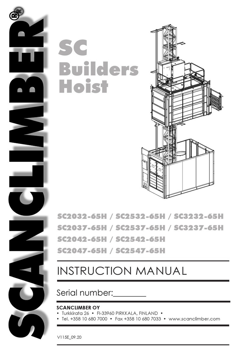
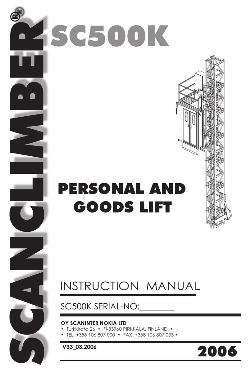
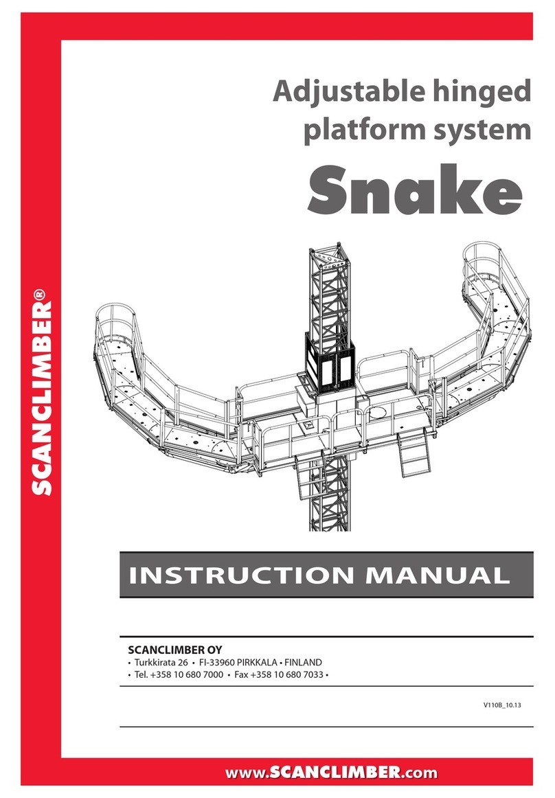
SCANCLIMBER SC4000 User manual

SC4000 SERIAL NO:________
20-140295-1-2
SC4000
INSTRUCTION MANUAL
V23C_09.13
SCANCLIMBER OY
• Turkkirata 26 • FI-33960 PIRKKALA, FINLAND •
• Tel. +358 10 680 7000 • Fax +358 10 680 7033 • www.scanclimber.com


CONTENTS
1. GENERAL INFORMATION ..................................................................... 3
1.1. General description..............................................................................3
1.2. Basic delivery scope of SC4000 on wheel chassis with 12.5m
platform ................................................................................................ 8
1.3. Warranty terms....................................................................................11
2. TECHNICAL INFORMATION AND ELECTRIC CHARTS.......................... 3
2.1. Technical specications.......................................................................3
2.2. Optional equipment............................................................................. 8
2.2.1. Minichassis ............................................................................................. 8
2.2.2. Telescopic extensions .........................................................................9
2.2.3. Mast assembly crane .........................................................................12
2.2.4. Chassis drive unit.................................................................................13
2.2.5. Centre jack..........................................................................................14
2.2.6 Weather cover ....................................................................................15
2.2.7. Wall anchoring....................................................................................15
2.3. Electrical installation........................................................................... 1 6
2.4. Requirements for the supply voltage .............................................. 1 7
3. SAFETY REGULATIONS AND LOADING TABLES ................................... 3
3.1. Notes .....................................................................................................3
3.2. Safety rules ............................................................................................3
3.3. Loading tables SC4000 single .............................................................5
3.4. Loading tables SC4000 twin .............................................................. 1 6
3.5. Instruction and warning labels on the machine .............................22
4. ERECTION AND DISMANTLING ............................................................ 3
4.1. Introductory notes ................................................................................3
4.2. Required tools .......................................................................................3
4.3. Tightening torques for screws and nuts..............................................4
4.4. Preparatory works ................................................................................5
4.5. Wall anchoring instructions .................................................................6
4.6. Assembly instructions.......................................................................... 1 7
4.6.1. SC4000 single....................................................................................... 1 7
4.6.2. SC4000 twin ......................................................................................... 2 8
4.6.3. Assembly of the telescopic extensions ............................................41
4.7. The check of assembled platform....................................................44
4.8. Platform disassembly .......................................................................... 4 6
5. OPERATIONAL INSTRUCTIONS ............................................................. 3
5.1. Instructions / warnings for the operators............................................3
5.2. Operation instructions ..........................................................................4
5.2.1. Scope of operator´s responsibilities ....................................................5
5.2.2. Procedures in emergency cases ........................................................5
5.3. Control instructions ............................................................................... 8
5.3.1. Lifting / lowering.................................................................................... 8

5.3 2. Transfer with chassis drive unit ...........................................................10
5.3 3. Safety harness......................................................................................12
5.4. Daily inspections .................................................................................13
5.5. Functional troubles .............................................................................14
6. SERVICE INSTRUCTIONS ..........................................................................3
6.1. Platform maintenance............................................................................3
6.2. Inspections................................................................................................4
6.2.1. Daily inspection........................................................................................4
6.2.2. Frequent inspections ...............................................................................5
6.3. Lubrication................................................................................................ 7
6.3.1. Capacity of gear oil tanks ...................................................................... 7
6.3.2. Denotation of oils and greases used..................................................... 8
6.3.3. Lubrication periods.................................................................................. 8
6.3.4. Platform lubrication schedule ................................................................9
6.4. Drawings illustrating the measurements and adjustment
procedures .............................................................................................12
6.4.1. Tightening torques for screws and nuts...............................................13
7. STORAGE AND TRANSPORT ....................................................................3
7.1. Storage instruction...................................................................................3
7.2. Transport instruction.................................................................................3
8. SPARE PARTS CATALOGUE WITH DRAWINGS ..........................................
See separate catalogue ..........................................................................
9. GEAR MOTORS........................................................................................1
10. INSPECTION FORMS................................................................................3
ERECTION FORM.......................................................................................3
DAILY INSPECTION FORM ........................................................................4
FREQUENT INSPECTION FORM.................................................................5
CONTENTS

is document is the instruction manual for Scanclimber SC4000 mast climbing work
platform.
is is a copy of the original instructions in English.
ese instructions are made according to Directive 2006/42/EC on machinery and the
European standard EN1495 + A2.
Original
ECDECLARATIONOFCONFORMITY
(Directive2006/42/EC,AnnexIIA)
Manufacturer:
ScanclimberOyScanclimberSp.zo.o.
Turkkirata26ul.Surowieckiego9
33960Pirkkala,Finland62‐200Gniezno,Poland
HerewithScanclimberOyandScanclimberSp.zo.odeclarethatmastclimbingworkplatform
ScanclimberSC4000,serialnumber:___
andallseparatelycertifiedavailableequipmentsforSC4000MCWPareinconformitywiththeprovisionsof
theMachineryDirective2006/42/EC,asamended,andwithnationalimplementinglegislation;European
StandardEN1495:1997+A2:2009andallotherdirectivesandEuropeanstandardswhicharementionedand
requiredtobeusedtogetherwithEN1495:1997+A2:2009.
ECtype‐examinationcertificate:
Registeredno.4420509376765‐006validfrom29.12.2009
TÜVNORDCERTGmbH
Langemarckstrasse20
45141Essen,Germany
NotifiedBody0044
Pirkkala05.06.2012
EerikNousiainen
CEO
ScanclimberGroup
SCANCLIMBER OY V120112
Turkkirata 26, FI-33960 PIRKKALA
Tel. +358 10 680 7000, Fax +358 10 680 7033
www.scanclimber.com

-----•
SCANC~IMBER
®

General information
1
SC4000 Pos 1
V23C_09.13
1. GENERAL INFORMATION
1. GENERAL INFORMATION......................................... 3
1.1. GENERAL DESCRIPTION........................................... 3
1.2. BASIC DELIVERY SCOPE OF SC4000 ON
WHEEL CHASSIS WITH 12.5 M PLATFORM .............. 8
1.3. WARRANTY TERMS.................................................. 11

General information
2V23C_09.13
SC4000 Pos 1

General information
3
SC4000 Pos 1
V23C_09.13
1. GENERAL INFORMATION
SCANCLIMBER SC4000 can be used
either as a single or twin mast climbing
platform. It is designed to position men/
women with their tools and other nec-
essary equipment and material for the
working in great heights.
SCANCLIMBERSC4000 can beuseddur-
ing all kind of works: assembly, n ishing,
cladding and painting of buildings, fa-
cade work and industrial objects. It can
be installed indoors as well as outdoors.
The unit is operated up and down with
push-buttonsof pendantcontrolbox. On
the box there is also an emergency stop
push-button.
SCANCLIMBER SC4000 consists of chas-
sis,mast and platformsectionswhich are
connected to the lifting frame.
1.1. GENERAL DESCRIPTION
Drawing 1.1. SC4000 on wheel chassis.
LEVELLING JACK
CHASSIS
TOW BAR
OUTRIGGER
CENTRE JACK
RAILING SECTION WITH
GATE AND LADDER
CHASSIS DRIVE UNIT
MAST
LIFTING FRAME
PLATFORM SECTION
MAST TOP CAP
20-140295-1-2

General information
4V23C_09.13
SC4000 Pos 1
!! IT IS NOT AL-
LOWED TO TOW
SC4000 ON PU-
BLIC STREETS !!
Drawing 1.2
SC4000 single on minichassis.
Mast consists of cross
hatching structure
mast sections which
are assembled one on
top of the other and
connected with the
mastscrewsets.Onone
sideofthe mast section
there is the rack.
Top cap is situated on
the top of the mast. It
works as a mechanical
stopping device.
Top cap is also used
asa hoistbracketwhen
hoisting the mast or the
whole SCANCLIMBER
SC4000. The maximum
hoistingcapacity ofthe
top cap is 5500 kg.
Thefreestandingheight
of mast, assembled
onto the wheel chas-
sis, is limited. By using
the anchoring system
it is possible to reach
the maximum height of
100 m. The minichassis
has been designed for
the narrow and close
worksites.
MINI CHASSIS
!
WALL ANCHOR
(VERTICALLY
ADJUSTABLE)
20-0295-102-1
Wheelchassis consists of a weldedframe with
four wheels, four telescopic outriggers can be
turned out with levelling jacks, used for setting
thechassis and mast inverticalposition.Chas-
sis drive unit is available for the wheel chassis
to make the movements at worksite easier.
Towingof theSCANCLIMBER SC4000 atwork-
site is possible with a tow bar.
LEVELLING JACK

General information
5
SC4000 Pos 1
V23C_09.13
By connecting two SC4000 SINGLES to-
getherwith platformhinged jointsyouwill
get a SC5000 TWIN with wider and more
effecient working area.
Drawing 1.3. SC4000 twin on minichassis.
Drawing 1.4. SC4000 twin on wheel chassis.
40-0295-85-K
40-0295-105-1

General information
6V23C_09.13
SC4000 Pos 1
Drawing1.6SC4000singlewithdimensions.
All outriggers extended, turned out on
mast side only.
Drawing 1.5 SC4000 single with di-
mensions. All outriggers turned out
and extended.
FREESTANDING HEIGHT 15 M
20-140295-1-1
FREESTANDING HEIGHT 15 M
20-0295-2-2

General information
7
SC4000 Pos 1
V23C_09.13
20-0295-102-1
Drawing 1.7. SC4000 single on minichassis. Minichassis with dimensions.
1591 mm /5’3’’
1350 mm /4’5’’
834 mm/2’9’’
1550 mm /5’1’’
1791 mm /5’11’’

General information
8V23C_09.13
SC4000 Pos 1
item description pcs
1. Wheel chassis 1
2. Telescopic outrigger with levelling jack 4
3. Centre jack 1
4. Ground plate 4+1
5. Tow bar 1
6. Chassis drive unit 1
7. Cable tray 1
8. Lifting frame 1
9. Mast section x)
10. Mast screw set 4 pcs / mast section
11. Mast top cap (with screw set 4 pcs) 1
12. Mast guard net 1
13. Mast guard net 1
14. Mast guard net 1
15. Counter part of limit switch (top and bottom position) 2
16. Signalling bar 2
17.
18. Platform section (1,68 x1,6 m) 4
19. Platform screw set 28
20. Railing (1,0 m) 5
21. Railing (1,6 m) 10
22. Railing with gate (1,6 m) 2
23. Railing coupler 2 (corner piece) with fastening screws 8
24. Railing coupler 1 (straight) with fastening screws 14
25.R. Railing coupler 3 (sidemounting) with fastening screws 2
25.L. Railing coupler 4 ( sidemounting) with fastening screws 2
26. Hex-socket cap-screw 38
27. Ladder 2
28. Side platform support 2
29. Side platform screw set 4
30. Anchor set x)
31. Top anchor pipes 2
32. Special tool (for platforms assembly) 1
33. Special tool (for jacks) 1
34. Platform section (1,68 x 1,0 m) (optional) 2
35. Special key (for safety brake) 1
36. Pendant control for drive of the chassis and
horizontal and vertical drive of the platform 1
37. Pendant control for safety brake test (single/twin unit) 1
38.R. Railing for basic platform section 1
38.L. Railing for basic platform section 1
x) Depending on the mast height
1.2. BASIC DELIVERY SCOPE OF SC4000 ON WHEEL
CHASSIS WITH 12.5 M PLATFORM (SEE PICTURE NO.
20-140295-1)

General information
9
SC4000 Pos 1
V23C_09.13
Drawing 1.8.
SC4000 single on wheel chassis with 12,5 m platform - basic delivery scope.
20-1098-1E

General information
10 V23C_09.13
SC4000 Pos 1
Parts and units, quantity of which de-
pends on the lifting height are specied
in the following table.
Quantity in brackets is for SC4000 TWIN.
TABLE OF PART QUANTITIES, WHICH DEPEND ON LIFTING HEIGHT
No. Part Drawing Lifting height/m
or spare
20 30 40 50 60 70 80 90 100
Quantity/pcs
1. Mast section PG100323 16 24 32 40 48 56 64 72 80x)
(32 48 64 80 96 112 128 144 160)
1.1. Mast bolt set 10005932 64 96 128 160 192 224 256 288 320
2. Wall anchors PG140045 1 2 3 4 5 6 6 7 8
Min. quantity of (2 4 6 8 10 12 12 14 16)
anchors for mast on
wheel chassis
Min. quantity of anchors 3 4 5 6 7 8 8 9 10
for mast on minichassis (6 8 10 12 14 16 16 18 20)
3. Cables in metres m 28 38 48 58 68 78 88 98 108
5 x 6 mm2 (56 76 96 116 136 156 176 196 216)
x) Basic unit includes one assembled mast section.
Part No
Hoisting platform below 100 m

General information
11
SC4000 Pos 1
V23C_09.13
1.3. WARRANTY TERMS
ThesellerwarrantsnewSCANCLIMBERmastclimbingworkplatform
is supplied free from defects in material and workmanship.
The warranty is valid for six (6) months from the date of
delivery.
The warranty of the equipment and parts manufactured by sub-
contractors is limited to the warranty of their respective manu-
factures.
address:
The warranty does not cover:
1. damage or loss caused by transportation
2. damage or loss caused by misconduct, misapplication or accident
3. damage or loss caused by negligence of instructions, service,
maintenance or storage
4. normal deterioration of the equipment and damage resulting from wear-
ing parts: material like rubber tyres, electrical equipment etc.
5. damage or loss caused by maintenance or repairs performed by
a nonauthorized service personnel
6. damage or loss caused by purchaser´s acts or omissions causing
alternations to the quality or structure of mast climber
7. any such indirect damage or loss as loss of prot and downtime cost etc.
No claim will be accepted if non-original parts, not approved of by the seller,
have been used.
Warrantyclaims shouldbedoneinwritingdescribingthe damageas completely
as possible and sent to the address below within fourteen (14) days from the
date of disclosure of the damage.
The warranty liability is limited, at the sellers discretion to
(1) replacing the damaged part or
(2) repairing the damaged part by the seller or by a subcontractor or
(3) granting a price reduction
The warranty of replaced or repaired part expires at the expiration time of the
warranty of the mast climber.
The purchaser is obliged to send the damaged part to the seller for inspection
by a request. Replaced or refunded parts become the property of the seller.
SCANCLIMBER OY
• Turkkirata 26 • FI-33960 PIRKKALA, FINLAND •
• Tel. +358 10 680 7000 • Fax +358 10 680 7033 • www.scanclimber.com

General information
12 V23C_09.13
SC4000 Pos 1

SC4000 Pos 2 1
V23C_09.13
Technical information
2. TECHNICAL INFORMATION
2. TECHNICAL INFORMATION AND ELECTRIC
CHARTS...................................................................3
2.1. TECHNICAL SPECIFICATIONS................................3
2.2. OPTIONAL EQUIPMENT .........................................8
2.2.1. ...MINICHASSIS......................................................8
2.2.2. ...TELESCOPIC EXTENSIONS ................................9
2.2.3. ...MAST ASSEMBLY CRANE.................................12
2.2.4. ...CHASSIS DRIVE UNIT........................................13
2.2.5. ...CENTRE JACK..................................................14
2.2.6 ...WEATHER COVER............................................15
2.2.7. ...WALL ANCHORING.........................................15
2.3. ELECTRICAL INSTALLATION.................................16
2.4. REQUIREMENTS FOR THE SUPPLY VOLTAGE .....17

Technical information
2V23C_09.13
SC4000 Pos 2
Table of contents
Other SCANCLIMBER Lifting System manuals

SCANCLIMBER
SCANCLIMBER 65H Series User manual

SCANCLIMBER
SCANCLIMBER SC2000K User manual

SCANCLIMBER
SCANCLIMBER SC500K User manual

SCANCLIMBER
SCANCLIMBER SC300K User manual

SCANCLIMBER
SCANCLIMBER SC2032-65 User manual

SCANCLIMBER
SCANCLIMBER LT500 User manual

SCANCLIMBER
SCANCLIMBER SC1300 User manual

SCANCLIMBER
SCANCLIMBER Snake User manual