Inficon Sensistor ILS500 F User manual

Operating Manual
Tracer Gas Filler
Sensistor ILS500 F/FHP
ninp69en1-02-(2201)
Catalog No.
590-580, 590-581
Type No. ILS.210.307
From software version
4.00.00

INFICON AB
Wahlbecksgatan 25A
SE-58216 Linköping
Sweden

INFICON Table of Contents
ILS500 F_FHP-Operation-manual-ninp69en1-02-(2201) iii
Table of Contents
1 About this manual ..........................................................................................................................................7
1.1 Target groups ...........................................................................................................................................7
2 Safety...............................................................................................................................................................8
2.1 Duties of the operator ...............................................................................................................................8
2.2 Intended use .............................................................................................................................................8
2.3 Owner requirements .................................................................................................................................8
2.4 Dangers ....................................................................................................................................................9
3 Description....................................................................................................................................................11
3.1 Intended Use ..........................................................................................................................................11
3.2 Available Configurations .........................................................................................................................11
3.3 Front View...............................................................................................................................................12
3.4 Rear View (Electrical) .............................................................................................................................13
3.5 Configuring Ports and Interfaces (Electrical) ..........................................................................................13
3.6 Rear View (Pneumatical) ........................................................................................................................14
3.7 Configuring Ports and Interfaces (Pneumatical) .....................................................................................15
3.8 Labels .....................................................................................................................................................15
3.9 Technical Data........................................................................................................................................16
3.9.1 Electrical Specifications .............................................................................................................. 16
3.9.2 Pneumatic Specifications............................................................................................................ 17
3.9.3 Other Data .................................................................................................................................. 18
3.9.4 Interfaces and Connectors.......................................................................................................... 19
3.9.4.1 RS232 ................................................................................................................................19
3.9.4.2 Input 1 (Optional) ...............................................................................................................21
3.9.4.3 Input 2 (Optional) ...............................................................................................................22
3.9.4.4 Status Output .....................................................................................................................22
3.9.4.5 Tooling Interface ................................................................................................................23
3.9.4.6 Control Output....................................................................................................................24
3.9.4.7 Power Input ........................................................................................................................25
3.9.4.8 Safety Interface ..................................................................................................................25
3.9.4.9 USB Port ............................................................................................................................26
4 Equipment and Storage ...............................................................................................................................28
4.1 Supplied Equipment................................................................................................................................28
4.2 Required Equipment ...............................................................................................................................29
4.3 Storage ...................................................................................................................................................29

Table of Contents INFICON
iv ILS500 F_FHP-Operation-manual-ninp69en1-02-(2201)
5 Setup..............................................................................................................................................................30
5.1 Placement of the ILS500 F/FHP .............................................................................................................30
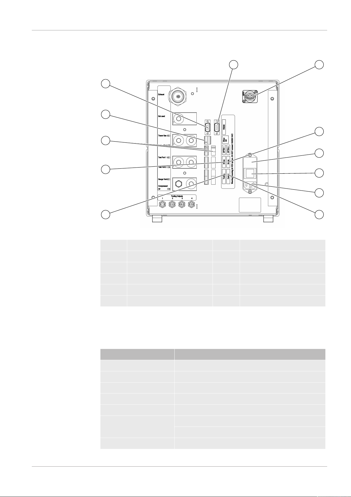
5.2 Electrical Connections ............................................................................................................................31
5.2.1 Setting Up an Emergency Stop................................................................................................... 31
5.2.2 Connecting to Mains ................................................................................................................... 31
5.2.3 Connecting Extra Features ......................................................................................................... 32
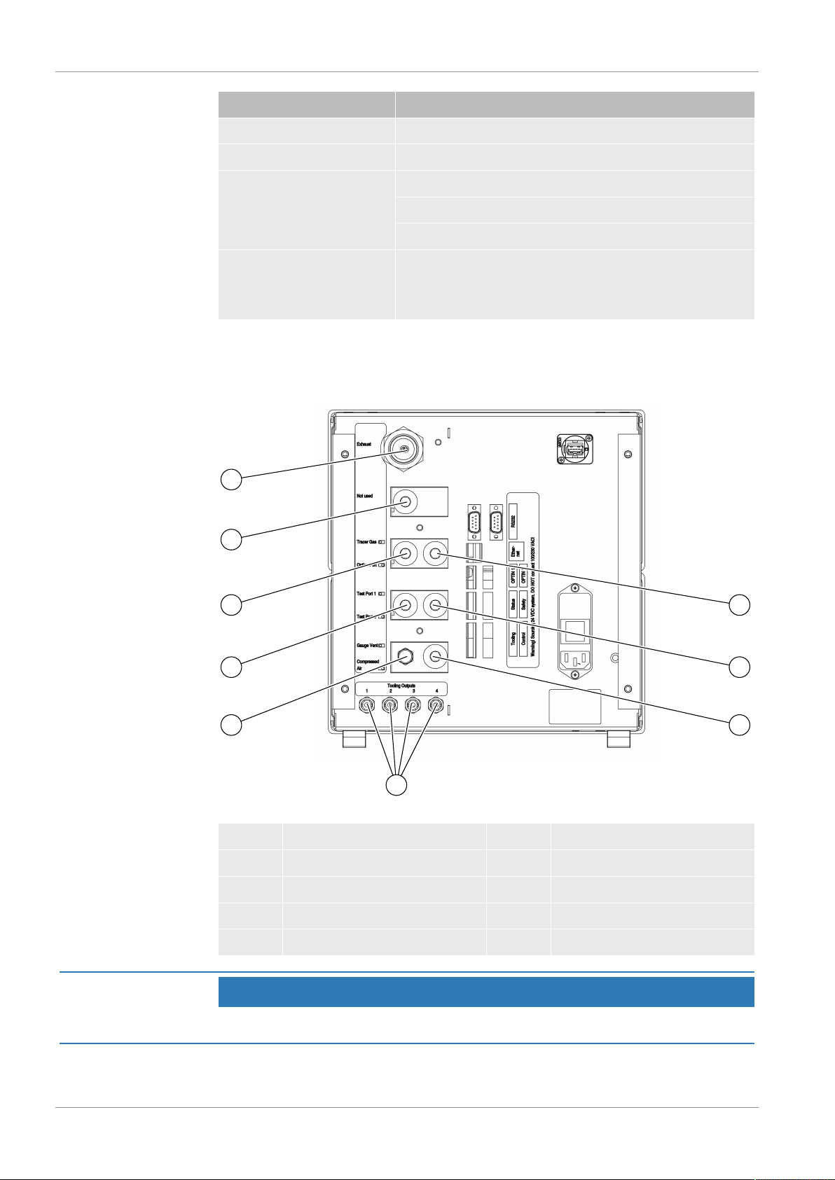
5.3 Pneumatic Connections..........................................................................................................................32
5.3.1 Connecting Compressed Air ....................................................................................................... 32
5.3.2 Connecting Tracer Gas............................................................................................................... 33
5.3.3 Connecting Exhaust to Air Vent .................................................................................................. 35
5.3.4 Connecting to Test Port 1 and 2 ................................................................................................. 36
5.3.5 Connecting Tooling ..................................................................................................................... 36
5.4 Set Up Test Area ....................................................................................................................................37
6 Menu System ................................................................................................................................................39
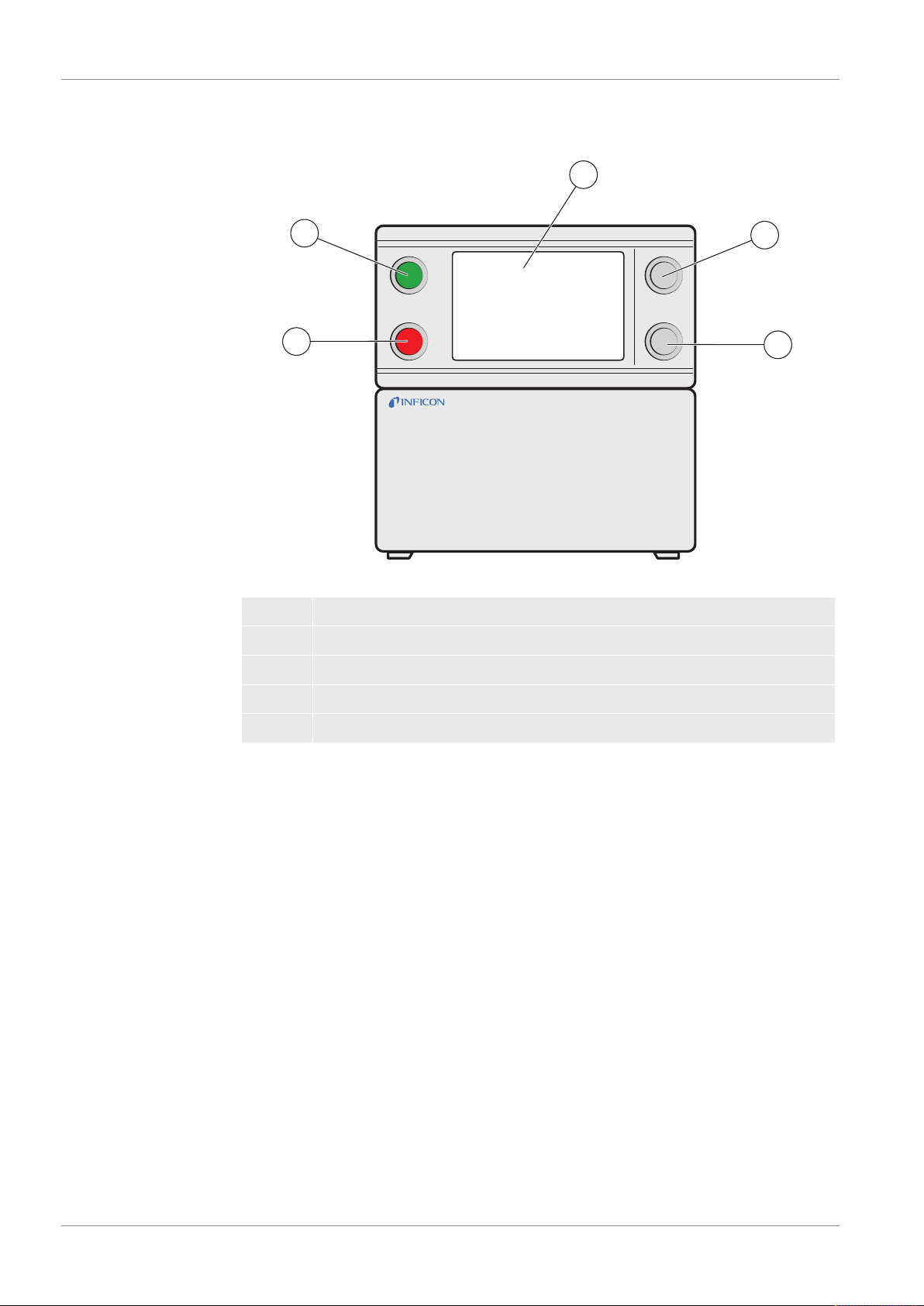
6.1 ILS500 F/FHP Display ............................................................................................................................39
6.1.1 Menu Buttons.............................................................................................................................. 39
6.1.2 Navigation and Other Buttons..................................................................................................... 39
6.1.3 Entering Numbers and Text ........................................................................................................ 40
6.1.4 Screen Saver .............................................................................................................................. 40
6.2 Passwords ..............................................................................................................................................41
6.2.1 Set Up New User ........................................................................................................................ 41
6.3 Menu Overview.......................................................................................................................................41
7 Using the ILS500 F/FHP ...............................................................................................................................47
7.1 Test Sequence........................................................................................................................................47
7.2 Run a Test ..............................................................................................................................................48
7.2.1 Start Up....................................................................................................................................... 48
7.2.2 Place the Test Object.................................................................................................................. 48
7.2.3 Perform Tracer Gas Filling.......................................................................................................... 48
8 Recipes..........................................................................................................................................................50
8.1 Recipe Overview.....................................................................................................................................50
8.2 Create a Recipe......................................................................................................................................51
8.2.1 New Recipe................................................................................................................................. 51
8.2.2 Modify a Recipe .......................................................................................................................... 52
8.3 Test Settings...........................................................................................................................................52
8.3.1 Tooling Connection ..................................................................................................................... 53

INFICON Table of Contents
ILS500 F_FHP-Operation-manual-ninp69en1-02-(2201) v
8.3.2 Pre Evacuation............................................................................................................................ 55
8.3.3 Gross Leak Tests........................................................................................................................ 56
8.3.4 Tracer Gas Filling........................................................................................................................ 58
8.3.5 Blockage Test ............................................................................................................................. 59
8.3.6 Gas Evacuation........................................................................................................................... 59
8.3.7 Tooling Disconnection................................................................................................................. 60
8.4 Optimizing the Test Cycle.......................................................................................................................60
8.4.1 Optimizing the Pre Evacuation Step ........................................................................................... 61
8.4.1.1 Calculate Tracer Gas Concentration..................................................................................61
8.4.1.2 Example - Calculate Tracer Gas Filling..............................................................................62
8.4.2 Optimizing the Tracer Gas Filling................................................................................................ 63
8.4.2.1 External Pressure Regulation ............................................................................................63
8.4.2.2 Internal Pressure Regulation..............................................................................................63
9 Troubleshooting ...........................................................................................................................................64
9.1 Fault Symptoms......................................................................................................................................64
9.2 Perform Hardware Test ..........................................................................................................................64
9.2.1 Hardware Error Messages .......................................................................................................... 75
9.2.2 Interpretation of Hardware Test Results ..................................................................................... 75
10 Maintenance Instructions ............................................................................................................................78
10.1 Maintenance Plan ...................................................................................................................................78
10.2 Maintenance ...........................................................................................................................................78
10.2.1 Tools and Safety Equipment....................................................................................................... 78
10.2.2 Interior View ................................................................................................................................ 79
10.2.3 Removing the Cover ................................................................................................................... 80
10.2.4 Cleaning or Replacing the Venturi Pump.................................................................................... 80
10.2.5 Replacing Gas Valves................................................................................................................. 82
10.2.6 Replacing Pilot Valves ................................................................................................................ 82
10.2.7 Replacing Sensors...................................................................................................................... 83
10.3 Functional Verification ............................................................................................................................83
11 Service...........................................................................................................................................................84
12 Spare Parts and Accessories ......................................................................................................................85
13 Support from INFICON .................................................................................................................................86
13.1 How to Contact INFICON .......................................................................................................................86
13.2 Returning Components to INFICON .......................................................................................................86
14 Disposal.........................................................................................................................................................87

Table of Contents INFICON
vi ILS500 F_FHP-Operation-manual-ninp69en1-02-(2201)
15 EU Declaration of Conformity .....................................................................................................................88
16 EC Declaration of Incorporation .................................................................................................................89
17 UK Declaration of Conformity .....................................................................................................................90
18 Appendix A....................................................................................................................................................91
18.1 Parameter Index .....................................................................................................................................91

INFICON About this manual | 1
ILS500 F_FHP-Operation-manual-ninp69en1-02-(2201) 7 / 94
1 About this manual
The purpose of this manual is to:
• Describe the working principles of the ILS500 F/FHP and its different parts
• Show examples of different types of test stations
• Teach the reader how to set up the ILS500 F/FHP for different test purposes
Document history
Revision Date Remark
a 10-2014 First edition
b 10-2021 Second edition
Warnings
DANGER
Imminent hazard resulting in death or serious injuries
WARNING
Hazardous situation resulting in potential death or serious injuries
CAUTION
Hazardous situation resulting in minor injuries
NOTICE
Hazardous situation resulting in damage to property or the environment
1.1 Target groups
These operating instructions are intended for the owner and for technically qualified
personnel with experience in leak detection technology and integration of leak
detection devices in leak detection systems. In addition, the installation and use of the
device require knowledge of electronic interfaces.

2 | Safety INFICON
8 / 94 ILS500 F_FHP-Operation-manual-ninp69en1-02-(2201)
2 Safety
2.1 Duties of the operator
• Read, observe, and follow the information in this manual and in the work
instructions provided by the owner. This concerns in particular the safety and
warning instructions.
• Always observe the complete operating instructions for all work.
• If you have any questions about operation or maintenance that are not answered
in this manual, contact customer service.
2.2 Intended use
The ILS500 F and ILS500 FHP tracer gas fillers are used to fill test objects with tracer
gas in a safe and controlled manner in conjunction with the leak detectors.
Improper use
• Use in radioactive areas
• Use of accessories or spare parts, which are not included in this instruction
manual
• Use outside the technical specifications, see Technical Data [}16]
• Aspiration of liquids into the device
• Operation without exhaust line on gas detection system
• Using the device in potentially explosive atmospheres
• Using the device with detectable defects or defective power switch
2.3 Owner requirements
The following notes are for companies or any person who is responsible for the safety
and effective use of the product by the user, employees or third parties.
Safety-conscious operation
• Operate the device only if it is in perfect technical condition and has no damage.
• Only operate the device properly in accordance with this instruction manual, in a
safety and risk conscious manner.
• Adhere to the following regulations and observe their compliance:
– Intended use
– Universally valid safety and accident prevention regulations
– International, national and local standards and guidelines

INFICON Safety | 2
ILS500 F_FHP-Operation-manual-ninp69en1-02-(2201) 9 / 94
– Additional device-related provisions and regulations
• Only use original parts or parts approved by the manufacturer.
• Keep this instruction manual available on site.
Personnel qualifications
• Only instructed personnel should be permitted to work with and on the device. The
instructed personnel must have received training on the device.
• Make sure that authorized personnel have read and understood the instruction
manual and all other applicable documents.
2.4 Dangers
• The ILS 500 F/FHP must never be introduced to pressures higher than that
approved for the object to be tested and never beyond the ILS 500 F/FHP
specification.
• Be sure to have a pressure relief valve in case of accidental tracer gas pressure
increase.
• When dealing with high pressures, a blast protection is needed between the test
ports and the test object.
• When dealing with test objects that cannot stand high pressure increase, make
sure to mount a flow control valve on the test ports.
• Make sure not to confound compressed air and tracer gas.
• INFICON can not take any responsibility for the consequences arising from
inappropriate use of certain test pressures.
Failure to observe the following precautions could result in
serious personal injury:
• Tracer Gases can be flammable or asphyxiating. Use only ready-made Tracer
Gas mixtures.
• Since the tracer gas mix contains no oxygen, releasing large amounts of the gas
in a confined space may lead to asphyxiation.
• Compressed gases contain a great deal of stored energy. Always carefully secure
gas bottles before connecting a pressure regulator. Never transport gas bottles
with a pressure regulator fitted.
• Pressurizing objects at too high pressures can lead to the object bursting. This in
turn can result in serious injury or even death. Never pressurize objects that have
not previously been burst-tested or have otherwise been approved for the test
pressure you intend to use.
• The ILS 500 F/FHP has no internal emergency stop circuit. The ILS 500 F/FHP is
prepared for integration into an external emergency stop circuit.

2 | Safety INFICON
10 / 94 ILS500 F_FHP-Operation-manual-ninp69en1-02-(2201)
• Check that all relevant legislation and safety standards are complied with before
putting the ILS 500 F/FHP into service. See further information under Setup
[}30].
Failure to observe the following precautions could result in
damage to the equipment:
• If the tracer gas filler suffers external damage, it must be checked and repaired by
a service organization authorized by INFICON.
• Always switch power off before connecting or disconnecting any cable.
• Before connecting the tracer gas, confirm that the connectors or test object is
designed for operating at the test pressure to be used.

INFICON Description | 3
ILS500 F_FHP-Operation-manual-ninp69en1-02-(2201) 11 / 94
3 Description
The Sensistor ILS500 F/FHP is a stand alone tracer gas filler with all necessary
functions integrated in one very compact housing. The purpose of the ILS500 F/FHP
is to make it possible to set up a fully automatic leak test system quickly, to a low cost.
The ILS500 F/FHP can also be combined with both hydrogen and helium INFICON
leak detectors.
All functions are accessible and programmable using a touch panel. The test
sequence is controlled by an integrated controller.
To make operation easier, a mouse or a keyboard can be connected to the USB port.
3.1 Intended Use
ILS500 F/FHP is designed for indoor use only.
ILS500 F/FHP is manually controlled using the START and STOP buttons and the
menu system of the touch panel. The screen also shows the steps of the test
sequence graphically and in plain text.
3.2 Available Configurations
Configuration Purpose
Sensistor ILS500 F For common tracer gas leak detection
Sensistor ILS500 FHP High Pressure (HP)
When a higher tracer gas pressure is needed.
The actual configuration is shown on the display during start-up and in the menu when
clicking Setup >> Info.

3 | Description INFICON
12 / 94 ILS500 F_FHP-Operation-manual-ninp69en1-02-(2201)
3.3 Front View
1
2
3
4
5
Fig.1: ILS500 F/FHP Front View
1 Red lamp
2 Green lamp
3 ILS500 F/FHP Touch panel
4 START button
5 STOP button

INFICON Description | 3
ILS500 F_FHP-Operation-manual-ninp69en1-02-(2201) 13 / 94
3.4 Rear View (Electrical)
1 2
3
4
6
5
78
9
10
11
12
Fig.2: Rear View (Electrical)
1 (not used) 2 USB Port
3 Safety Interface 4 Fuses
5 Power Switch 6 Power Input
7 Control Output 8 Tooling Interface
9 Status Output 10 Inputs 1 and 2 (optional)
11 Ethernet 12 RS232
For more information, refer to Technical Data [}16].
3.5 Configuring Ports and Interfaces (Electrical)
Port/Interface Connect
Safety Interface Emergency Stop Circuit
Power Input Power Cable
Control Output Optional External Valves
Tooling Interface External sensors for tooling control
Status Output Light Tower etc.
Input 1 (optional) Analogue Input (not supported by std software)
Digital Input (not supported by std software)
Input 2 Active Holder for Hand Probe

3 | Description INFICON
14 / 94 ILS500 F_FHP-Operation-manual-ninp69en1-02-(2201)
Port/Interface Connect
(if ISH2000 Leak Detector is connected).
Ethernet Ethernet (remote view and control of touch panel)
RS232 Serial Printer
Logging Device (e.g. PC).
Remote Control (START, STOP etc.).
USB The USB port can be used to connect a mouse, an
external keyboard, or a flash drive (for download and
upload of recipes or to save screen dumps).
3.6 Rear View (Pneumatical)
1
2
4
6
5
7
8
9
3
Fig.3: Rear View (Pneumatical)
1 Optional Port 2 Test Port 2
3 Compressed Air Input 4 Tooling Valve Outputs 1-4
5 Vacuum Gauge Vent 6 Test Port 1
7 Tracer Gas Input 8 Plugged Port
9 Exhaust
NOTICE
► Do not remove the plug from the plugged port in pos. 8.

INFICON Description | 3
ILS500 F_FHP-Operation-manual-ninp69en1-02-(2201) 15 / 94
3.7 Configuring Ports and Interfaces (Pneumatical)
Port/Interface Port Thread
Exhaust Barb Fitting:
ID 25 mm (1 in.)
Tracer Gas Input
Test Port 1
Test Port 2
Compressed Air Input
BSP 3/8" (NPT 3/8" adaptor included)
Tooling Valve Outputs 1-4 Hose Connectors:
OD 4 mm (0.16 in.)
3.8 Labels
Fig.4: Device Label
Fig.5: Tooling Label

3 | Description INFICON
16 / 94 ILS500 F_FHP-Operation-manual-ninp69en1-02-(2201)
Fig.6: Pneumatical label (left) and electrical label (right)
3.9 Technical Data
275 mm (10.8 in.) 364 mm (14.3 in.)
294 mm (11.6 in.)
3.9.1 Electrical Specifications
Electrical Supply
Mains Voltage Single Phase

INFICON Description | 3
ILS500 F_FHP-Operation-manual-ninp69en1-02-(2201) 17 / 94
Electrical Supply
110-240VAC 50/60 Hz
Current 1.0 A at 100 VAC
0.45 A at 230 VAC
Power Rating 120 W max
33 W typical average
Inrush Current Max 40 A
Mains Connector IEC/EN 60320-1/C14
Recommended Fuse
Rating
2 A slow
6.3 x 32 mm, 0.2 x 1.3 in. (2 needed)
3.9.2 Pneumatic Specifications
Compressed Air Supply
Pressure Std Model 0.35–0.7 MPag
(3.5–7.0 barg)
(50–100 psig)
Reduced vacuum capacity
below:
0.5 MPag
(5.0 barg)
(70 psig)
HP model 0.5–0.7 MPag
(5.0–7.0 barg)
(70–100 psig)
Peak Consumption at 6
barg (87 psig)
240 l/min (508 SCFH)
Quality Oil free and filtered to 5 µm
Dew point Max 10°C (50°F)
Tracer Gas Supply
Composition Inert non-condensing gas
Pressure Std Model 0.005–1.0 MPag
(0.05–10.0 barg)
(0.72–145 psig)
HP model 0.02–3.0 MPag
(0.2–30.0 barg)
(3–435 psig)

3 | Description INFICON
18 / 94 ILS500 F_FHP-Operation-manual-ninp69en1-02-(2201)
Tracer Gas Supply
Quality Industrial grade purity
(>95% purity)
Exhaust
Capacity in Exhaust Duct Min 30 m3/h (1000 SCFH)
Dimensions of Hose
Leading to Duct
ID 25 mm (1 in.)
Pneumatic
Valve bore* 7 mm (0.28 in.)
*: Capacity is given for 500 mm (20 in.) of ID 10 mm (0.4 in.) hose between ILS500 F/
FHP and test volume.
Evacuation
Max vacuum -85 kPag (-0.85 barg, -12.3 psig)
Capacity 0.4 s/l to -50 kPag (-0.5 barg, -7.2 psig)
1.5 s/l to -80 kPag (-0.8 barg, -11.6 psig)
Filling
Capacity at 1 MPag supply 0.1 s/l to 0.6 MPag (6,0 barg, 87 psig)
Tooling Output Valves
Valve type Normally closed, 3/2 valve
Qn160 std l/min
Cv0.16 USGPM/psig
Gas and Air Connection
Ports Female ISO 3/8"
(ISO to NPT 3/8" adapter included)
Hose connector 4 of OD 10 mm (0.4 in.) connectors included
3.9.3 Other Data
General Data
Dimensions 295 x 275 x 330 mm (12 x 11 x 13 in.)
Weight 15.1 kg (33.3 lb.)
Ambient temperature 10–40°C (50–100°F)
Ambient humidity 85% RH (non condensing)
Protection IP30

INFICON Description | 3
ILS500 F_FHP-Operation-manual-ninp69en1-02-(2201) 19 / 94
3.9.4 Interfaces and Connectors
All interfaces signals except the serial. Communication interfaces are discrete 24 VDC
logic signals.
Output signals (OUT) are sourcing transistor outputs. Input signals (IN) are transistor
inputs.
Max current of each signal is given in the tables below. Total current (sum) must,
however, be within instrument specification.
NOTICE
Outputs are not relay types.
► Do not connect external drive source such as 24 V or 100/230 VAC.
3.9.4.1 RS232
Connector: 9 pin male D-sub
Purpose: Connection of serial printer or logging device (e.g. PC or PLC)
Cable: Standard female to female file transfer cable (null modem)
Baud Rate: 9600 default (1200 - 115200 selectable)
Pin Signal Specification
1 Not used Standard RS232C
2 RD Data rate 9600 baud
3 TD Data bits 8
4 Not used Stop bits 1
5 SG Parity none
6 Not used Flow ctrl none
7 Not used
8 Not used
9 Not used

3 | Description INFICON
20 / 94 ILS500 F_FHP-Operation-manual-ninp69en1-02-(2201)
Printing of results
The printer port prints the result of every test. In hand probe mode the result printed is
“ACCEPT” or “REJECT” followed by date & time and recipe name (if used) and end
Char New Line (0A, LF).<09> (Char Tab, 09) is used as a separator.
For Example: "TEST_ACCE<09>2013-09-04 13:23:03<09>Factory Default<0A>"
If the test cycle is rejected by any other test this will be printed. Followed with date,
time and recipe name. Hardware error prints “ERROR”.
For example: “ERROR<09>2013-09-04<09>Factory Default<0A>”.
On the ILS500 (Service/RS232), you can choose if you want to include time and date
in every result from the ILS500 or not. If it’s on the result will be:
"TEST_ACCE<09>2013- 09-04 13:23:03<09>Factory Default<0A>" and if it’s off:
“TEST_ACCE<0A>".
When filling is successfully completed FILL OK is printed. No information about time
and date is printed.
Results from ILS500 F/FHP
Results Explanation
TEST_ACCE Test accepted (if a leak detector is connected)
TEST_REJE Test rejected (if a Leka detector is connected)
USER_FAIL User has pressed stop
EVAC_FAIL Evacuation failed
VDEC_FAIL Vacuum decay test failed
FILL_FAIL Tracer gas filling failed
PDEC_FAIL Pressure decay test failed
BLOC_FAIL Blockage test failed
REFI_FAIL Tracer gas refill failed
TEST_STRT Test cycle started
TEST_DONE Test cycle finished
FILL_DONE Filling completed
RECH_DONE Recipe change done
RECH_FAIL Recipe change failed
ERROR Hardware error on ILS500
Commands
The printer port can also be used to control the ILS500 F/FHP. The most commonly
used functions can be started/configured over the RS232 interface. Always use New
Line (0A,LF) as end character.
Other manuals for Sensistor ILS500 F
1
This manual suits for next models
1
Table of contents
Other Inficon Laboratory Equipment manuals
Popular Laboratory Equipment manuals by other brands

Grant-bio
Grant-bio PHMP operating instructions

MRC
MRC MIXP Series Operation manual

Electron
Electron Thermo 3920 Operating and maintenance manual

IKA
IKA RCT basic operating instructions

Bibby Sterilin
Bibby Sterilin stuart SM5 Instructions for use

GE HEALTHCARE
GE HEALTHCARE Monitor UV-900 operating instructions