manuals.online logo
Brands
  1. Home
  2. •
  3. Brands
  4. •
  5. Inficon
  6. •
  7. Measuring Instrument
  8. •
  9. Inficon SKY CDG045 Series User manual

Inficon SKY CDG045 Series User manual

SKY™ Capacitance
Diaphragm Gauge
CDG045
CDG045-H
Operating Manual
Incl. Declaration of Conformity
tina07e1-b (0304)
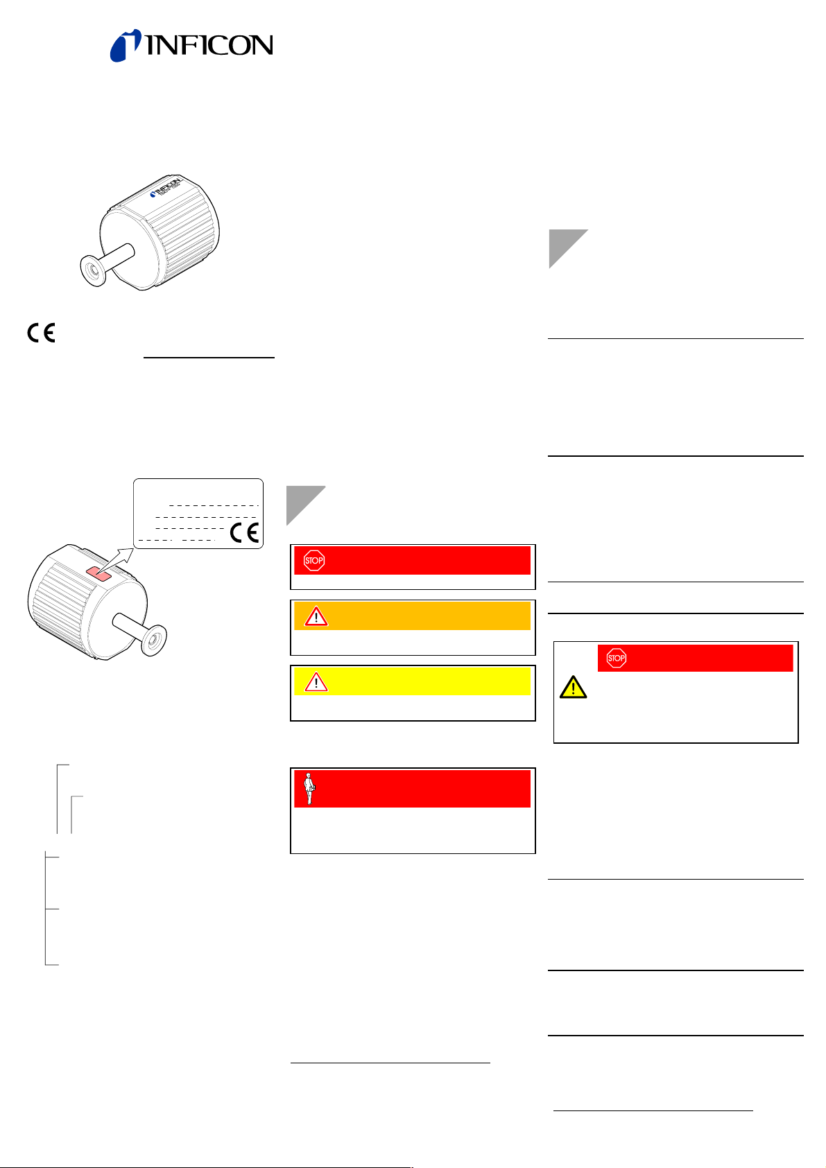
Product Identification
In all communications with INFICON, please specify the in-
formation given on the product nameplate. For convenient
reference transfer this information into the diagram below.
Model:
PN:
SN:
V W
INFICON AG, LI-9496 Balzers
Validity
This document applies to products with the following part
numbers:
CDG045:
360-010
0 Þ!"-Rohr
1 ÞDN 16 ISO-KF
2
ÞDN 16 CF-R
3
Þ8 VCR
0 Þ10-1 … 1000 Torr (F.S.)
1 Þ 10-2 … 100 Torr (F.S.)
2 Þ10-3 … 10 Torr (F.S.)
4 Þ10-4 … 1 Torr (F.S.)
5 Þ10-5 … 0.1 Torr (F.S.)
0 ÞTorr
1 ÞPa
2 Þmbar
0 Þ1.33×101… 133322 Pa (F.S.)
1 Þ 1.33×100… 13332.2 Pa (F.S.)
2 Þ1.33×10⁻¹ … 1333.22 Pa (F.S.)
4 Þ1.33×10⁻² … 133.322 Pa (F.S.)
5 Þ1.33×10⁻³ … 13.3322 Pa (F.S.)
0 Þ1.1×10⁻¹ … 1100 mbar (F.S.)
1 Þ 10-2 … 100 mbar (F.S.)
2 Þ10-3 … 10 mbar (F.S.)
4 Þ10-4 … 1 mbar (F.S.)
5 Þ10-5 … 0.1 mbar (F.S.)
CDG045-H High Speed:
371-030 (10-4 … 1 Torr (F.S.), DN 16 ISO-KF)
371-031 (10-5 … 0.1 Torr (F.S.), DN 16 ISO-KF)
371-032 (10-4 … 1 Torr (F.S.), 8 VCR)
371-033 (10-5 … 0.1 Torr (F.S.), 8 VCR)
The part number (PN) can be taken from the product name-
plate.
If not indicated otherwise in the legends, the illustrations in
this document correspond to gauges with the DN 16 ISO-KF
vacuum connection. They apply other vacuum connections
by analogy.
We reserve the right to make technical changes without prior
notice.
All dimensions in mm.
Intended Use
The temperature controlled SKY™ Capacitance Diaphragm
Gauges of the CDG045 and CDG045-H series are intended
for absolute pressure measurement of gases in the pressure
ranges specified in section "Validity".
The gauges can be operated in connection with an INFICON
Vacuum Gauge Controller or another appropriate controller.
Functional Principle
The SKY™ Capacitance Diaphragm Gauges consist of a
capacitive sensor element made of aluminum oxide ceramic
and electronics which convert the capacitance change into a
DC voltage output signal.
The output signal is linear to the measured pressure and
independent of the gas type.1)
The sensor is heated and its temperature kept constant at
45 °C to prevent contamination by process products and by
products.
Trademarks
SKY™ INFICON GmbH
VCR® Swagelok Marketing Co.
Safety
Symbols Used
DANGER
Information on preventing any kind of physical injury.
WARNING
Information on preventing extensive equipment and
environmental damage.
Caution
Information on correct handling or use. Disregard can lead
to malfunctions or minor equipment damage.
Personnel Qualifications
Skilled personnel
All work described in this document may only be carried out
by persons who have suitable technical training and the
necessary experience or who have been instructed by the
end-user of the product.
General Safety Instructions
· Adhere to the applicable regulations and take the nec-
essary precautions for the process media used.
Consider possible reactions with the product materials.
· Adhere to the applicable regulations and take the nec-
essary precautions for all work you are going to do and
consider the safety instructions in this document.
· Before beginning to work, find out whether any vacuum
components are contaminated. Adhere to the relevant
regulations and take the necessary precautions when
handling contaminated parts.
Communicate the safety instructions to all other users.
1) For p < 1 mbar and TGauge ¹TVacuum the linearity of a
temperature controlled gauge is influenced by the thermal
transpiration (gas type dependent) at the maximum in the
same order of magnitude as the zero point stability.
See K. F. Poulter et al., Vacuum 33, 331 (1983); W. Jitschin
and P. Röhl, J. Vac. Sci. Technol. A, Vol. 5, No. 3, 1987 .
Liability and Warranty
INFICON assumes no liability and the warranty becomes null
and void if the end-user or third parties
· disregard the information in this document
· use the product in a non-conforming manner
· make any kind of interventions (modifications, alterations
etc.) on the product
· use the product with accessories not listed in the product
documentation.
The end-user assumes the responsibility in conjunction with
the process media used.
Technical Data
Measurement range ®"Validity"
Accuracy 0.15% of reading
Resolution
360-X1X … 362-X1X
364-X1X, 365-X1X
371-030 … 371-033
0.0015% F.S.
0.0025% F.S.
0.0025% F.S.
Temperature effect on zero
360-X1X … 364-X1X
365-X1X
371-030, 371-032
371-031, 371-033
0.0025% F.S./ °C
0.0050% F.S./ °C
0.0025% F.S./ °C
0.0050% F.S./ °C
Temperature effect on span
360-X1X … 365-X1X
371-030 … 371-033
0.01% of reading/ °C
Gas type dependence none1)
Output signal (measuring signal)
Measurement range
Voltage range
0 … +10.0 V
-11.0 V … +11.0 V
Relationship voltage-pressure linear1)
Output impedance 200 W(short-circuit proof)
Minimum loaded impedance 10 kW
Response time
360-X1X … 362-X1X
364-X1X, 365-X1X
371-030 … 371-033
30 ms
100 ms
30 ms
Gauge identification Resistance 13.2 kWrefer-
enced to supply common
Supply
DANGER
The gauge may only be connected to power
supplies, instruments or control devices that
conform to the requirements of a grounded
protective extra-low voltage (SELV-E according
to EN 61010). The connection to the gauge has
to be fused.2)
Supply voltage at the gauge
at pin 7
or pin 11
15 VDC ±5%
18.0 … 26.4 VDC
Power consumption (depending
on supply voltage)
during heat-up
at operating temperature
9 … 19 W
4 … 5 W
Internal fuse 1 AT, slow, automatic
reset (Polifuse)
The gauge is protected against polarity change of the supply
voltage.
Electrical connector D-Sub, 15-pin, male,
screwlock UNC 4-40
Sensor cable 5 conductors plus
shielding
Cable length £50 m (5x0.50 mm²)
For longer cables, bigger conductor cross-sections are
required (Rconductor £1.0 W).
Grounding concept
Vacuum connection – signal
common ®"Electrical Connection"
Supply common – signal
common
conducted separately; for
differential measurement
2) INFICON controllers fulfill these requirements.
Materials exposed to the vacuum
Flange, tube, protective
chamber, plasma shield
Sensor and diaphragm
Sensor – diaphragm
connection
Ceramic - metal connection
stainless steel 316L
ceramic (Al2O3 ³99.5%)
glass ceramics solder
AgCu hard solder,
Vacon 70 (28% Ni,
23% Co, 49% Fe)
Internal volume 7 cm3
Admissible pressure
360-X1X
361-X1X … 364-X1X
365-X1X
371-030, 371-032
371-031, 371-033
£2250 Torr (absolute)
£300 kPa (absolute)
£3 bar (absolute)
£1500 Torr (absolute)
£200 kPa (absolute)
£2 bar (absolute)
£1000 Torr (absolute)
£133.3 kPa (absolute)
£1.33 bar (absolute)
£1500 Torr (absolute)
£1000 Torr (absolute)
Admissible temperatures
Operation
Vacuum connection
Storage
+15 … +40 °C
£90 °C
–40 … +65 °C
Relative humidity £80% at temperatures
£+31 °C decreasing to
50% at +40 °C
Mounting orientation any ®"Installation"
Use indoors only, altitude up
to 2000 m
Type of protection IP 30
Dimensions [mm]
DN 16 ISO-KF
36X-X11
371-030
371-031
8 VCR
female
36X-X13
371-032
371-033
DN 16 CF-R
36X-X12
36X-X10
48
AD½"
46
74.5
48
82.5
80
Weight
36X-X10
36X-X11
36X-X12
36X-X13
371-032, 371-033
371-030, 371-031
600 g
590 g
620 g
610 g
610 g
590 g
Relationship Measuring Signal –
Pressure
12345678910
0
0.9×F.S.
0.5×F.S.
0.6×F.S.
1.0×F.S.
0.7×F.S.
0.8×F.S.
0.1×F.S.
0.2×F.S.
0.3×F.S.
0.4×F.S.
1.1×F.S.
Pressure p
Measuring signal Uout [V]
0.0×F.S.
p = (Uout / 10 V) × p(F.S.)
Example: Gauge with 10 Torr F.S.
Measuring signal Uout = 6 V
p = (6 V / 10 V) × 10 Torr
= 0.6 × 10 Torr = 6 Torr
Conversion Torr «Pascal
Torr mbar3) Pa3)
c 1.00 1013.25 / 760 =
1.3332…
101325 / 760 =
133.3224…
Installation
Vacuum Connection
DANGER
Caution: overpressure in the vacuum system
>750 Torr, 100000 Pa, 1 bar
Injury caused by released parts and harm
caused by escaping process gases can result if
clamps are opened while the vacuum system is
pressurized.
Do not open any clamps while the vacuum sys-
tem is pressurized. Use the type clamps which
are suited to overpressure.
DANGER
Caution: protective ground
Products that are not correctly connected to
ground can be extremely hazardous in the event
of a fault.
Electrically connect the gauge to the grounded
vacuum chamber. This connection must conform
to the requirements of a protective connection
according to EN 61010:
· CF and 8 VCR flanges fulfill this requirement.
· For gauges with a KF flange, use a conduc-
tive metallic clamping ring.
· For gauges with a !" tube, take appropriate
measures to fulfill this requirement.
Caution
Caution: vacuum component
Dirt and damages impair the function of the
vacuum component.
When handling vacuum components, take ap-
propriate measures to ensure cleanliness and
prevent damages.
3) Source: NPL (National Physical Laboratory)
Guide to the Measurement of Pressure and Vacuum
ISBN 0904457x / 1998.
Caution
Caution: dirt sensitive area
Touching the product or parts thereof with bare
hands increases the desorption rate.
Always wear clean, lint-free gloves and use
clean tools when working in this area.
The gauge may be mounted in any orientation. How-
ever, it should be mounted so that no vibrations
occur and that no particles and condensates can
penetrate into the measuring chamber. If adjustment
should be possible after the gauge has been in-
stalled, be sure to install it so that potentiometers
<zero coarse> and <zero fine> can be accessed
with a screw driver.
Remove the protective lid or the threaded plug and connect
the product to the vacuum system.
Threaded plug
Seal
or
Clamp
Seal with centering ring
or
Seal with centering
ring and filter
Protective lid
Keep the protective lid/threaded plug.
tina07e1-b (0304)
Original: German tina07d1-b (0304)
Electrical Connection
Make sure the vacuum connection is properly made
(®"Vacuum Connection").
If no sensor cable is available, make one according to
the following diagram.
7
15
5
11
12
2
case
10
Ident
15 8
91
D-Sub, 15-pin
female
soldering side
Pin assignment
Pin 2 Signal output
(Measuring signal)
Pin 5 Supply common
Pin 7 Supply (+15 V)
Pin 10 Identification *)
Pin 11 Supply (+18 ... +26.4 V)
Pin 12 Signal common
Pin 15 Housing
case Connector housing
·Connect
only one supply voltage
(+15 V or +18 … +26.4 V).
·Pins 1, 3, 4, 6, 8, 9, 13, 14 are not
assigned in the gauge.
*) ®"Technical Data"
Connect the sensor cable to the gauge.
Secure the cable socket to the gauge connector with
the lock screws.
Connect the sensor cable to the controller.
Operation
Put the gauge into operation. If you are operating the gauge
with an INFICON Vacuum Gauge Controller, adjust the
measurement range (®&[1, 2]).
Allow for a warm-up time of at least 1 hour, or for high
precision measurements, of at least 2 hours.
Gas type dependence
The measured value is independent of the gas type.1)
Zeroing the Gauge
Before operating the gauge for the first time, adjust the zero.
Due to long time operation or contamination, a zero drift
could occur and periodic zeroing may become necessary.
Adjust the zero at the ambient temperature at which the
gauge is normally operated.
Evacuate the gauge to a pressure in accordance with
the table below:
Recommended maximum pressure for
zero adjustment
360-X1X
361-X1X
362-X1X
364-X1X
365-X1X
371-030
371-031
371-032
371-033
<5´10-2 Torr
<5´10-3 Torr
<5´10-4 Torr
<5´10-5 Torr
<5´10-6 Torr
<5´10-5 Torr
<5´10-6 Torr
<5´10-5 Torr
<5´10-6 Torr
<6.65´100Pa
<6.65´10-1 Pa
<6.65´10-2 Pa
<6.65´10-3 Pa
<6.65´10-4 Pa
<5´10-2 mbar
<5´10-3 mbar
<5´10-4 mbar
<5´10-5 mbar
<5´10-6 mbar
Operate the gauge for 1 to 2 hours (until the reading is
stable).
Connect a reliable, accurate, correctly calibrated
instrument with at least 4 digits to the (measuring)
signal output of the gauge.
Only initial operation:
To compensate for the influence of the mounting
orientation, adjust the output signal to -0.2 … +0.2 VDC
via the <zero coarse> potentiometer.
Using a screwdriver (1.5 mm), adjust <zero fine> so
that the output signal is 0.000 VDC.
If you are using the INFICON Vacuum Gauge
Controller, you can adjust the zero on the controller
(®&[1, 2]).
Deinstallation
DANGER
Caution: contaminated parts
Contaminated parts can be detrimental to health
and environment.
Before beginning to work, find out whether any
parts are contaminated. Adhere to the relevant
regulations and take the necessary precautions
when handling contaminated parts.
Caution
Caution: vacuum component
Dirt and damages impair the function of the
vacuum component.
When handling vacuum components, take ap-
propriate measures to ensure cleanliness and
prevent damages.
Caution
Caution: dirt sensitive area
Touching the product or parts thereof with bare
hands increases the desorption rate.
Always wear clean, lint-free gloves and use
clean tools when working in this area.
Vent the vacuum system.
Turn the gauge off.
Loosen the lock screws and unplug the sensor cable.
Remove the gauge from the vacuum system.
Threaded plug
or
Protective lid
Maintenance, Repair
Under clean operating conditions, the product requires no
maintenance.
Gauge failures due to contamination are not covered
by the warranty.
INFICON assumes no liability and the warranty be-
comes null and void if any repair work is carried out
by the end-user or third parties.
Returning the Product
WARNING
Caution: forwarding contaminated products
Contaminated products (e.g. radioactive, toxic,
caustic or microbiological hazard) can be detri-
mental to health and environment.
Products returned to INFICON should preferably
be free of harmful substances. Adhere to the for-
warding regulations of all involved countries and
forwarding companies and enclose a duly com-
pleted declaration of contamination.
Products that are not clearly declared as "free of harmful sub-
stances" are decontaminated at the expense of the customer.
Products not accompanied by a duly completed declaration of
contamination are returned to the sender at his own expense.
Disposal
DANGER
Caution: contaminated parts
Contaminated parts can be detrimental to health
and environment.
Before beginning to work, find out whether any
parts are contaminated. Adhere to the relevant
regulations and take the necessary precautions
when handling contaminated parts.
N
WARNING
Caution: substances detrimental to the
environment
Products or parts thereof (mechanical and elec-
tric components, operating fluids etc.) can be
detrimental to the environment.
Dispose of such substances in accordance with
the relevant local regulations.
Separating the components
After disassembling the product, separate its components
according to the following criteria:
· Contaminated components
Contaminated components (radioactive, toxic, caustic, or
biological hazard etc.) must be decontaminated in accor-
dance with the relevant national regulations, separated
according to their materials, and disposed of.
· Other components
Such components must be separated according to their
materials and recycled.
Further Information
&[1] www.inficon.com
Operating Manual
Single-Channel Controller VGC401
tinb01e1
INFICON AG, LI–9496 Balzers, Liechtenstein
&[2] www.Inficon.com
Operating Manual
Vacuum Gauge Controller VGC032
tinb02e1
INFICON AG, LI–9496 Balzers, Liechtenstein
Declaration of Contamination
Legally binding declaration:
We hereby declare that the information on this form is
complete and accurate and that we will assume any further
costs that may arise. The contaminated product will be dis-
patched in accordance with the applicable regulations.
Organization/company
Address
Post code, place
Phone Fax
Email
Name
Company stamp
Copies: Original for addressee
1 copy for accompanying documents
1 copy for file of sender
Operating fluid(s) used
(Must be drained before shipping.)
The service, repair, and/or disposal of vacuum equipment and com-
ponents will only be carried out if a correctly completed declaration
has been submitted. Non-completion will result in delay.
This declaration may only be completed (in block letters) and signed
by authorized and qualified staff.
Reason for return
Description of product
Type
Part number
Serial number
no qyes
q
Used in copper process
Seal product in plastic
bag and mark it with a
corresponding label.
This form can be downloaded from our website.
The product is free
of any substances
which are damaging
to health.
yes q
Process related contamination of product:
toxic no q1) yes q
corrosive no q1) yes q
biological hazard no qyes q2)
explosive no qyes q2)
radioactive no qyes q2)
other harmful substances no q1) yes q
1) or not containing any
amount of hazardous
residues that exceed the
permissible exposure limits
2) Products thus
contaminated
will not be
accepted with-
out written
evidence of
decontami -
nation.
Precautions associated with
substance
Action if human
contact
Trade/product name
manufacturer
Chemical name
(or symbol)
Harmful substances, gases and/or
by-products
Please list all substances, gases, and by-products
which the product may have come into contact with:
Declaration of Conformity
We, INFICON, hereby declare that the equip-
ment mentioned below complies with the
provisions of the Directive relating to electrical
equipment designed for use within certain
voltage limits 73/23/EEC and the Directive
relating to electromagnetic compatibility
89/336/EEC.
SKY™ Capacitance
Diaphragm Gauge
CDG045
CDG045-H
Part numbers
360-010 360-110 360-210 361-010
360-011 360-111 360-211 361-011
360-012 360-112 360-212 361-012
360-013 360-113 360-213 361-013
361-110 361-210 362-010 362-110
361-111 361-211 362-011 362-111
361-112 361-212 362-012 362-112
361-113 361-213 362-013 362-113
362-210 364-010 364-110 364-210
362-211 364-011 364-111 364-211
362-212 364-012 364-112 364-212
362-213 364-013 364-113 364-213
365-010 365-110 365-210 371-030
365-011 365-111 365-211 371-031
365-012 365-112 365-212 371-032
365-013 365-113 365-213 371-033
Standards
Harmonized and international/national standards and
specifications:
· EN 61010 (Safety requirements for electrical
equipment for measurement, control
and laboratory use)
· EN 50081-1 (Electromagnetic compatibility:
generic emission standard)
· EN 50082-2 (Electromagnetic compatibility:
generic immunity standard)
Signatures
INFICON AG, Balzers
31 March 2003 1 April 2003
Reto Süssli
Product Marketing
Management
Dr. Georg Sele
Technical Support Manager
Quality Representative
LI–9496 Balzers
Liechtenstein
Tel +423 / 388 3111
Fax +423 / 388 3700
[email protected]
www.inficon.com

This manual suits for next models

1

Other Inficon Measuring Instrument manuals

Inficon CDG045D2 User manual

Inficon

Inficon CDG045D2 User manual

Inficon HAPSITE ER User manual

Inficon

Inficon HAPSITE ER User manual

Inficon LDM150R User manual

Inficon

Inficon LDM150R User manual

Inficon AP29ECO User manual

Inficon

Inficon AP29ECO User manual

Inficon UL1000 Fab Release Note

Inficon

Inficon UL1000 Fab Release Note

Inficon Micro GC Fusion 2-Module User manual

Inficon

Inficon Micro GC Fusion 2-Module User manual

Inficon 3000 Micro GC User manual

Inficon

Inficon 3000 Micro GC User manual

Inficon LDM150 User manual

Inficon

Inficon LDM150 User manual

Inficon Transpector SPS User manual

Inficon

Inficon Transpector SPS User manual

Inficon 700-600-G1 User manual

Inficon

Inficon 700-600-G1 User manual

Inficon Micro GC Fusion Assembly instructions

Inficon

Inficon Micro GC Fusion Assembly instructions

Inficon Sensistor ILS500 User manual

Inficon

Inficon Sensistor ILS500 User manual

Inficon PCG550 User manual

Inficon

Inficon PCG550 User manual

Inficon Micro GC Fusion User manual

Inficon

Inficon Micro GC Fusion User manual

Inficon CO Check User manual

Inficon

Inficon CO Check User manual

Inficon HAPSITE ER User manual

Inficon

Inficon HAPSITE ER User manual

Inficon Pilot Plus User manual

Inficon

Inficon Pilot Plus User manual

Inficon CDG025D2 User manual

Inficon

Inficon CDG025D2 User manual

Inficon Sensistor ILS500 User manual

Inficon

Inficon Sensistor ILS500 User manual

Inficon VGC402 User manual

Inficon

Inficon VGC402 User manual

Inficon Micro GC Fusion User manual

Inficon

Inficon Micro GC Fusion User manual

Inficon FLUE-Mate User manual

Inficon

Inficon FLUE-Mate User manual

Inficon Gemini MAG500 User manual

Inficon

Inficon Gemini MAG500 User manual

Inficon 3000 Micro GC User manual

Inficon

Inficon 3000 Micro GC User manual

Popular Measuring Instrument manuals by other brands

TREND DAR/200 Original instructions

TREND

TREND DAR/200 Original instructions

Greenlee FG01 G-Series Smart Pull instruction manual

Greenlee

Greenlee FG01 G-Series Smart Pull instruction manual

Resonance R37A quick user's handbook

Resonance

Resonance R37A quick user's handbook

Nidec FG-3000R-S Operation manual

Nidec

Nidec FG-3000R-S Operation manual

Spectrum Technologies LightScout 3415F product manual

Spectrum Technologies

Spectrum Technologies LightScout 3415F product manual

Pessl iMETOS RadioNode user manual

Pessl

Pessl iMETOS RadioNode user manual

Eurolube Equipment 16717 Instructions for use

Eurolube Equipment

Eurolube Equipment 16717 Instructions for use

Avery Weigh-Tronix 615XL Service manual

Avery Weigh-Tronix

Avery Weigh-Tronix 615XL Service manual

BEHA Unitest SF 100 Instuction manual

BEHA

BEHA Unitest SF 100 Instuction manual

Gima VITAL-SNET user manual

Gima

Gima VITAL-SNET user manual

Lumel ND1 user manual

Lumel

Lumel ND1 user manual

WIKA 230.15 operating instructions

WIKA

WIKA 230.15 operating instructions

Varian PVG-502 instruction manual

Varian

Varian PVG-502 instruction manual

socomec COUNTIS E43 instruction manual

socomec

socomec COUNTIS E43 instruction manual

BTI PROFILINE Disfix 50 manual

BTI

BTI PROFILINE Disfix 50 manual

Hitachi C22T instruction manual

Hitachi

Hitachi C22T instruction manual

Tuthill FILL-RITE 900DB Owners installation, operation, and safety manual

Tuthill

Tuthill FILL-RITE 900DB Owners installation, operation, and safety manual

RaycoWylie i4000 Calibration instructions

RaycoWylie

RaycoWylie i4000 Calibration instructions

manuals.online logo
manuals.online logoBrands
  • About & Mission
  • Contact us
  • Privacy Policy
  • Terms and Conditions

Copyright 2025 Manuals.Online. All Rights Reserved.