Infiltrator CM-1060 User manual

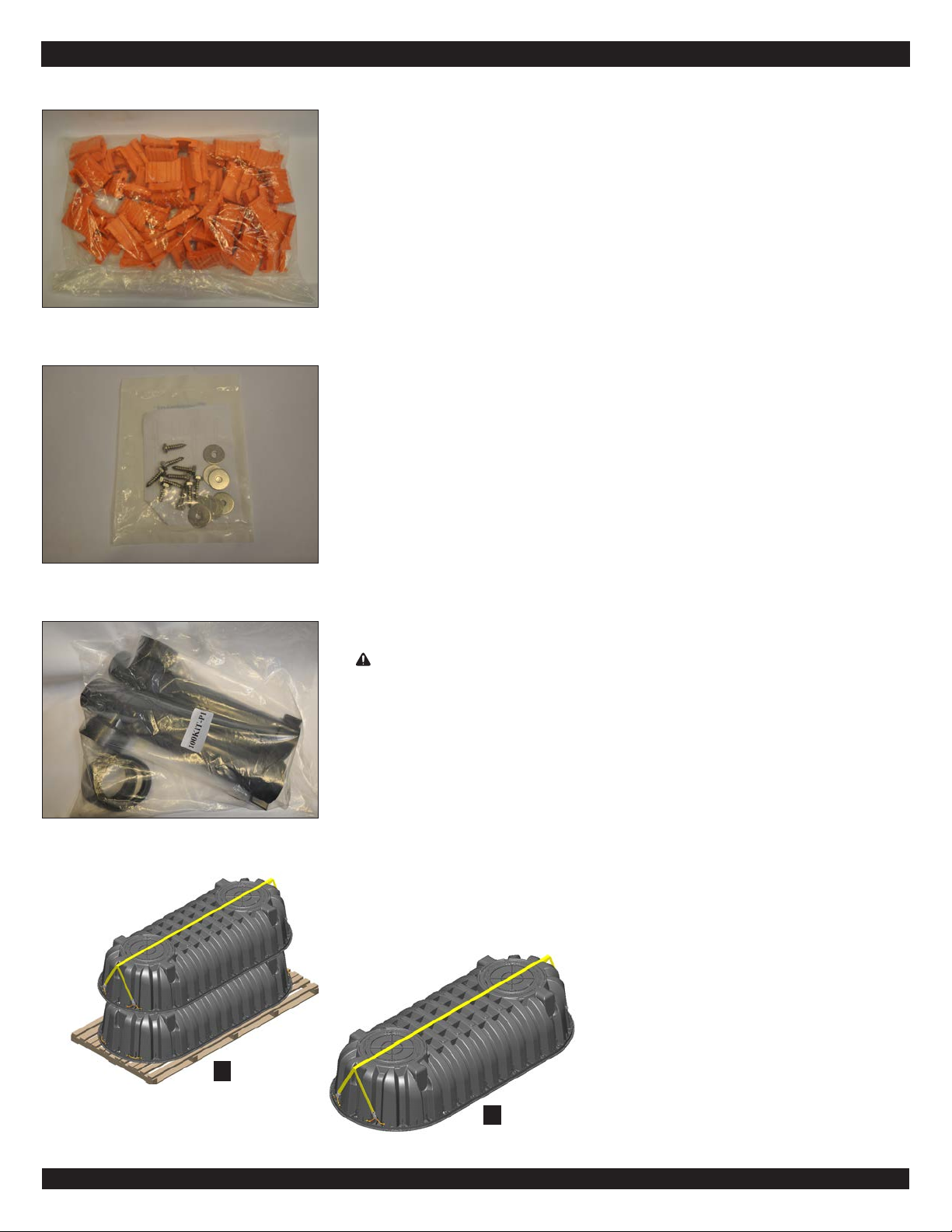
SupportPosts(2) SeamClips(64) Bae
Lids (2)
Before you Begin
The following is a complete list
of tank components:
•Tanktophalf
•Tankbottomhalf(withpre-installed
mid-seamgasket)
•Bae(two-compartmentcongurationonly)
•Seamclips(64)
•Supportposts(2)
•Lids(2)
•Lidshippingscrews(4)andwashers(4)
•Lidspacers(1)
•Lidscrewkits(2)
•Plumbingkit
The following tools facilitate
tank assembl
y:
•Forklift(5,000lb[2,268kg]capacity,
32”[0.81m]loadcenter,min.66”[1.68m]
arm,min.12’[3.66m]pickheight)
•InltratorLiftingStrapAssembly*
•22oz.[0.6L]spraybottle*
•16oz.[0.5L]liquidsoap*
•Utilityknife
•Coarse-bristledpaintbrush
•Metalhammer(16-20oz.[0.5kg])
•Rubbermallet
•Holesaw(5”[125mm]diameter)
•Nutdriver(3/8”,5/16”sockets)
•Cleanrags
•Headlamporashlight
•Screwgun
•Safetyglasses
*Supplied in Inltrator CM-1060 Starter Kit
Infiltrator CM-1060 Tank
Assembly Instructions
Itisrecommendedthataminimumoftwopeopleparticipatetosafelyassemblethetank.
Assemblers must wear safety glasses during the entire assembly. The top half of the
tankweighsapproximately169pounds(77kg)andthebottomhalfofthetankweighs
approximately162pounds(74kg)foratotalapproximateweightof331pounds(151kg).
Eachtankhalfmustbeliftedapproximately30 inches (750 mm) above groundduring
the assembly process. There must be enough side and overhead clearance to freely
maneuverthetankcomponentsandtooperateliftingmachinerywhenused.
TheCM-1060tankmustbeassembledbyanInltratorWaterTechnologiesAuthorized
Assembler. Tanks assembled by unauthorized assemblers will not be warrantied by
InltratorWaterTechnologies.AsignedcopyoftheCM-1060TankAssemblyChecklist&
AssemblyAuthorizationisrequiredforallAuthorizedAssemblers.
IMPLOSIONS MAY CAUSE SERIOUS INJURY
Follow Infiltrator Water Technologies, vacuum test instructions
NEVER EXCEED 2.5 inches mercury vacuum pressure
WARNING: These assembly instructions do not include a protocol for vacuum testing the CM-1060 tank. If required,
vacuumtestsontheCM-1060shallonlybeperformedinstrictaccordancewithInltrator’sCM-1060tankvacuumtesting
guidance documents. Failure to follow an Inltrator vacuum-testing protocol and/or exceeding 2.5 inches (63 mm) of
mercuryvacuumpressurecouldresultinpersonalharm.NeverapplyapositiveairpressuretotheCM-1060tank.Inltrator
willnotbeliableforanyproblemsthatarisefromsuchunauthorizeduse.
WARNING
Tanktopand
bottomhalves
Contact Infiltrator Water Technologies’ Technical Services Department for assistance at 1-800-221-4436
MARCH2022
Contact Infiltrator Water Technologies’ Technical Services Department for assistance at 1-800-221-4436
(2-compartmentcongurationonly)
AlignmentDowels(22)
Inltrator CM-1060 Tank Assembly Instructions Page 2
Contact Infiltrator Water Technologies’ Technical Services Department for assistance at 1-800-221-4436
Seam Clips (64)
LidScrewKit
P1PlumbingKit
Components CM-1060 Tank Pallet Handling
CM-1060palletsholdeither5or10tanks.
Overall Dimensions (for10-tankpallet)
• Stackedtanks:134”Lx62”Wx79”H(3.4mLx1.6mLx2.0mH)
• Stackedtanksonpallet:136”Lx67”Wx86”H(3.5mLx1.7mLx2.2mH)
Weight:3,600lbs(1,633kg)
Aforkliftthathasthefollowingminimumspecicationsisneededtosafelyhandleando
loadtheCM-1060pallet:5,000lb(2,268kg)capacity,32”(0.81m)loadcenter,minimum66”
(1.68m)armandminimum12’(3.66m)pickheight.
The tank halves must be safely removed from the pallet using the Inltrator Lifting Strap
Assembly.The CM-1060 tank pallets should never be tipped over!TheInltrator
Lifting Strap Assembly is sized to pick up a maximum of 4 tank halves at a time using
a forklift. The safety lock spring hooks are to be connected to the rope handles on the
endwallsofeach tank. Setthetankhalvesona clean surface topreventdamage or the
introductionofdirtanddebrisintothemid-seamareawherethegasket,gasketgroove,and
molded-indowelsarelocated.Setthetankhalvesonacleansurface,pallet,acrossseveral
4”x4”s, or a tarp to prevent damage or introducing dirt and debris to the mid-seam area
wherethegasketislocated.Neversetthetankhalfwiththegasketonanysurfacewiththe
gasketfacingdownward.
Tank Assembly
1.
RemoveallplasticwrapandstrappingfromtheCM-1060tankandcomponentsshipping
pallet.Ifserialnumbersneedtoberecorded,Inltratorrecommendsrecordingthemwhile
thetankhalvesarestackedonthepallet.Theserialnumberislocatedatthemid-seam
ontheoutletend.
2.
Using the Inltrator Lifting Strap Assembly, attach the four lifting strap hooks to
the CM-1060 rope handles, located two on either end of the tank bottom half.
Slowly lift the inverted tank bottom straight up and o of the tank top nested below.
WARNING: TThe Inltrator Lifting Strap Assembly supplied with the starter kit
is sized to pick up a maximum of four Inltrator tank halves at one time. Never lift
more than four tank halves at one time with the Inltrator Lifting Strap Assembly.
The Inltrator Lifting Strap Assembly is intended for use ONLY with Inltrator tanks
in accordance with these instructions; any other use of the Inltrator Lifting Strap
Assembly is prohibited. Inltrator Water Technologies will not be liable for any
problems that arise from unauthorized use of the Inltrator Lifting Strap Assembly.
Note: Never set the tank half with the mid-seam area facing downward without the use of
4”x4”s on a clean surface, pallet, or clean tarp to prevent damage or the introduction of
dirt and debris into the mid-seam area where the gasket, gasket groove, and molded-in
dowels are located.
3. Lift and set the tank bottom half down on 4”x4”s above a clean surface or pallet, to
preventdamage or the introductionofdirtanddebristothemid-seamareawherethe
gasketgroove,andmolded-indowelsarelocated.
2
3
Contact Infiltrator Water Technologies’ Technical Services Department for assistance at 1-800-221-4436
Inltrator CM-1060 Tank Assembly Instructions Page 3
4. RemovetheInltratorLiftingStrapAssemblyfromthetankhalf.Positionyourselfandyourassemblypartnerononesideofthetank.
Usingtwoofthefourliftinghandles,oneoneitherendofthetankhalf,liftandtilttheinvertedbottomtankhalf.Together,gentlyrollthe
tankbottomhalfontoitsatbasesothattheangegrooveandmid-seamgasketarefacingupwards.Placetherotatedtankbottomon
aclean,dry,levelsurfacesothatitisstable.
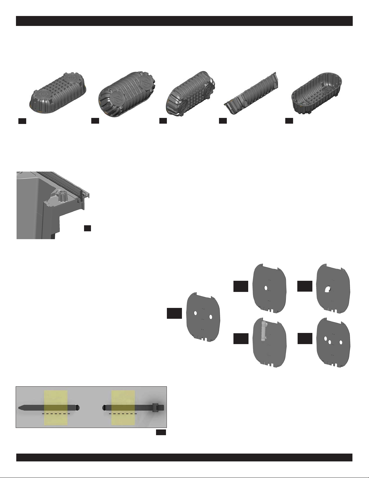
6. Identify the appropriate perforated bae port opening(s)
corresponding to the desired bae conguration below.
Carefullyremovetheperforatedopeningsbyknocking the
portcenterwithahammerormallet.Baeconguration25
shallbeusedinallstatesandprovinces,withthefollowing
limitedexceptions:
•15–Kentucky
•15E(requireselbowattachmentinbaeport)–
Alaska,Arizona,NewMexico
•15T(requiresteeattachmentinbaeport)–
Delaware,Pennsylvania
•35–Minnesota,Indiana
Note: If you are assembling a 15E bae, use the Inltrator
IM-1060 15E Bae Assembly Instructions document. If you
are assembling a 15T bae, use the Inltrator IM-1060 15T
Bae Assembly Instructions document. For all other bae
congurations, continue to Step 7.
7.Preparethebaetiewrapendsbyslittingthetapethatsecuresthem
tothebaeforshipping.Theslitshouldbemadejustaboveorbelow
thetiewrapendsandparalleltothelengthofthetiewrapends.This
willfacilitatefasteningofthebaetotheverticalsupportpostinStep
18.
4B
4A
5
6
(15)
6
(15T)
6
(25)
6
(15E)
6
(35)
slit tape
7
5.
Visuallyinspect the gasket toensurethat it isundamaged,seatedproperlyinthegrooveand freeof
materialsthatmaycompromisethewatertightnessoftheconnection.Thegasketinspectionshallinclude
anexaminationwhileviewingthetankfromboththetopandsideperspectives.Whenviewingfromthe
top,visually examinethegasketfordamage,anundulatingappearance(wherethegasketisnotfully
insertedintothegrooveanditsheightvaries),dirtanddebris,andanyothersignsofdefectordamage.
Whenviewingfromtheside,positionyoureyesatgasketheighttoevaluatetheheightofthetopofthe
gasketaroundthe entiremid-seamperimeter. Looking horizontallyacrossthe tank at mid-seam level
(fromtopofgaskettotopofgasketacrossthetankaxes),inspectthegasketalongthelongandshort
axesofthetank.Verifythatthegasketdoesnotundulate,wherethetopelevationofthegasketvaries.
Correctdecienciesifidentied.Ifthegasketisnotproperlyseatedinthegroove,manuallypressitinto
place.Useacoarse-bristledpaintbrushandcleanragstothoroughlyremoveanydirtordebrispresent
onthegasket.
4E4C 4D

Contact Infiltrator Water Technologies’ Technical Services Department for assistance at 1-800-221-4436
Inltrator CM-1060 Tank Assembly Instructions Page 4
8. Fold the tank baffle along the
perforationsasshown.Thefolds
are made toward the side of the
bafflewiththetiewrapends.
9. Insertthefoldedbaeintothebaeslotontheoutletsideofthetankbottomhalf.Theslotsonthebaebottomedgewillindexto
verticalribswithinthebaeslotonthetankbottomhalf.Thiswillresultinthetopfoldedportionofthebaepointingtowardstheoutlet
endofthetank.Donotunfoldthebaeatthistime.
10. Beforejoiningthetankhalves,lla22oz.(0.6L)spraybottlewith8oz.(0.25L)ofliquidsoapmixedwith14oz.(0.4L)oftapwater(1/3
+2/3mixture).Applyanevencoatofsoapywatertoallsurfacesoftheexposedgasketalongitsentirelength.Spraythegasketdirectly
fromabovesobothsidesofthegasketarelubricatedequally.Applysoapywatertoallowplacementofthetanktophalfwhensurfaces
arestillwet.ThiswillfacilitateengagementofthegasketinthegrooveonthetanktophalfduringtankassemblyinStep12.
8A
9A 9B 10
8B 8C
8D
11. UsingtheInltratorLiftingStrapAssembly,attachthefourliftingstrapstotheCM-1060rope
handles,locatedtwooneitherendofthetanktophalf.Slowlyliftthetanktopstraightupand
oofitslocation.
12.The CM-1060 features molded-in alignment dowels. The
molded-inalignmmentdowelsandreceivingholesalternate
between corrugations in the CM-1060 bottom and top
halves.Carefullylowerthetanktophalfontothetankbottom
half,aligningthetopandbottomtankhalfalignmentdowels
with the corresponding receiving holes. Once the top half
hasbeenloweredontothebottomhalf,positionyoureyes
atgasketheight andevaluatetheseam. Inspecttheseam
aroundtheentireperimeterofthetank.Visuallyinspectthe
seamandverifythatthegasketissecurelyseatedwithinthe
gasketgrooveofthetanktopandbottomhalves.Verifythat
theInltratorLiftingStrapAssemblyisnotcaughtwithinthe
seambeforeproceedingtoStep13.
13.
Identify clip-attachment locations along the mid-seam where the straight
sidewalltransitionstothecurvedendwall,asshowninimageNo.13A.Two
clips are attached at each of four locations at the inlet and outlet ends of
thetank as shown. At eachclip attachment location, push the top tank half
downwardtoengagethegasketinthetoptankhalf.Foralleightclips,place
theopensideofa seam clip against the joined seam rail of the tankhalves
at a 45-degree angle relative to the seam rail. These seam clips must be
attachedalongtheseamrailfromtheoutsideintowardsthetankcenterline.
Usingahammerandholdingthetopandbottomsidesoftheseamclip,tap
theseamclipalongthetankseamrail;theclipwillpulltowardtheseamrail.
Engagethecliptoafullstopoverthelockingtabs;theseamclipwillclickinto
placewhenproperlyengaged.Theseamclipisdesignedtolockinplacewith
twoorthreeswiftblowsofahammer.Ifsubstantialresistanceisencountered
13A
11
12A
12B

Contact Infiltrator Water Technologies’ Technical Services Department for assistance at 1-800-221-4436
Inltrator CM-1060 Tank Assembly Instructions Page 5
15. Slowlyrollthejoinedtankontoitssidealongitslongaxis.The
tankwillresttiltedasshown.Donotover-rotatethetankordrag
thetankalongthemid-seamfromthisposition,asdoingsomay
damagethetank.
Note: If you are assembling a one-compartment tank conguration
without a bae, then proceed to Step 17. Otherwise, continue to
Step 18.
16. Reachinthroughtheaccessopeningandunfoldthetankbaeandinserttheunfoldedtopcornerbaesectionsintothebaesloton
thetanktophalf.
15A
16A 16B 16C 16D
15B
17B
17. Insertthesupportpostthroughthetankaccessporton
theinletside of thetank.Placeone end ofthepostinthe
bottomcorrugationwiththepostseat,beyondthepostseat.
Do not yet engage the post end in the bottom post seat.
Swingtheoppositepostendintothesamecorrugationwith
thetoppostseat.Donotyetengagethepostendinthetop
postseat.Onceeachpostendisinsidethesamecorrugation
withthepostseats,thepostbottomcanbeinsertedintothe
bottomseat,andthenthetopcanbeinsertedintothetop
seat.Arubbermalletmaybeusedtofacilitateproperpost
seating. Repeat this process with a post through the tank
accessportontheoutletsideofthetank.Useaheadlamp
orashlightasneeded.
17A
CAUTION! Do not use a metal hammer to strike the support posts as this may cause permanent damage.
Note: If you are assembling a one-compartment tank conguration without a bae, then proceed to Step 19. Otherwise, continue to Step 18.
14. Usinganutdriverwith3/8”socket,unscrewand
remove the two lids from the tank top half (two
#14 hex-head shipping screws with washers per
lid)andspacers.Setthelidsasideandreservethe
four shipping screws, washers and spacers for
lateruseinStep22.Iftheinletandoutletholesare
pre-drilled then spacers are not needed and will
notbepresent.Optional: The lids can be removed
prior to Step 11 if preferred.
14A
engagingtheseamclips,removethetopofthetankandinspectthegasketfordamage,anundulatingappearance(wherethegasket
isnotfullyinsertedintothegrooveanditsheightvaries),dirtanddebris,andanyothersignsofdefectordamage,asdescribedinStep
5.Onceengaged,theseamclipcannotberemovedwithoutdamagingtheseamcliporthetanklockingtabs.Attachtheadjacentclip.
Attachtheremainingsixendclipsinthesamemannertonishthisstep.ThiswillmaintainseamconnectivityduringassemblySteps15
to19thatrequiretiltingthetank.Optional: All seam clips can be installed at this point of the assembly if preferred.
13B 13C 13D
14B
Table of contents
Popular Tank Equipment manuals by other brands


Astro Pneumatic Tool
Astro Pneumatic Tool PT2-4 quick start guide

Franklin Fueling Systems
Franklin Fueling Systems EVO 600 Operation guide

TransTank
TransTank TopCrop Operator's handbook

WELBA
WELBA TW-32 quick start

Amtrol
Amtrol FILL-TROL FT-109 Installation & operation instructions

Regulus
Regulus RBC 200 Installation and operation manual


