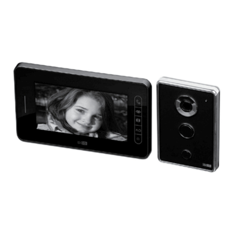
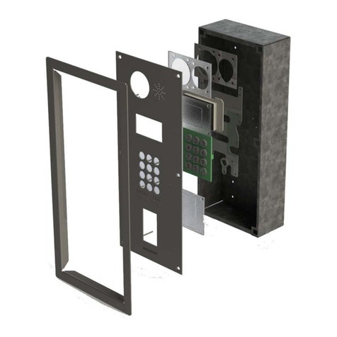
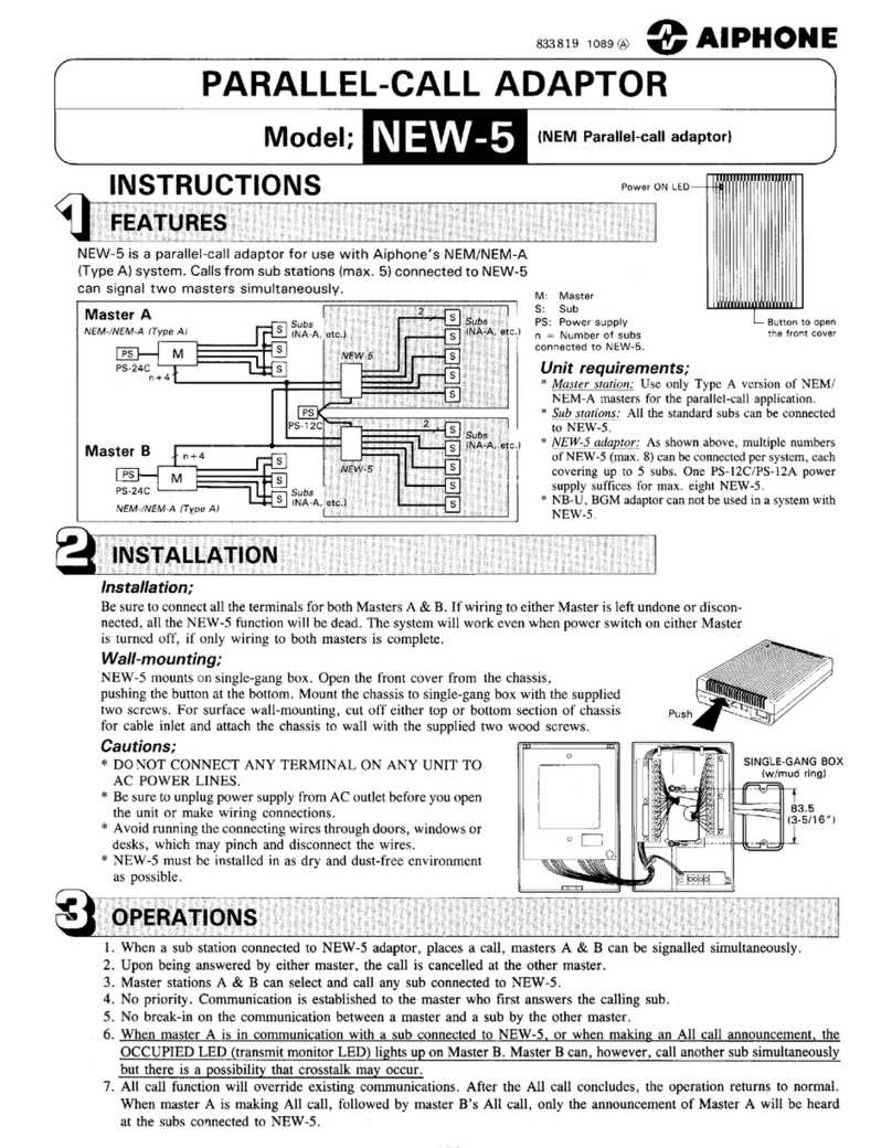
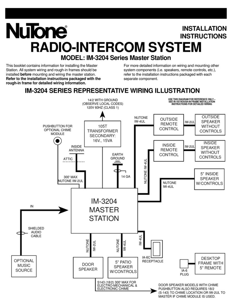
Infinite Play Small User manual

Installation and operation manual
Z1101-Z1102
Z2101-Z2102

SMALL
ENTRANCE PANEL INSTALLATION
ART. Z1101 – Z1102
Semi-surface mounted installation
1) Install a flush box of universal type 503 (InfinitePlay ZT503 - Vimar
V71303 - Bticino 503) or round of 60mm diameter, in vertical
position at a height of 160 cm from the floor to the top edge, as
shown in the figure.
Fix the chassis frame to the box using the 2 screws.
2) Wire the electronics assembly as shown through the RJ45
connector.
Position the Small Entrance Panel license tarting from the top and
then turning downwards.
Z1101 / Z1102
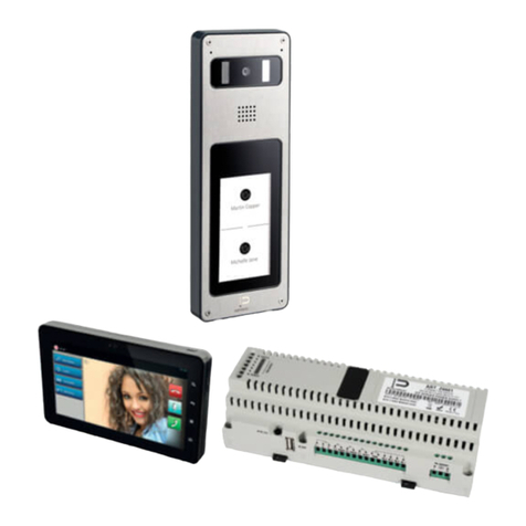
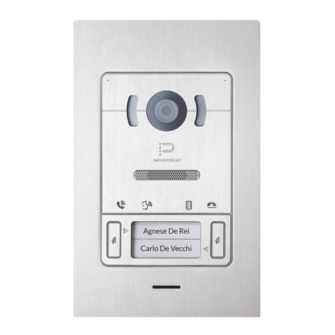
Small audio-video entrance panel for INFINITEPLAY video door entry systems.
2
EN
3) Fix the Small Entrance Panel using the 2 screws M3x12 Torx
included. 4) Insert the card names and close the lid

SMALL
5) Place the frame from the top and turning down. 6) Unscrew slightly the M3 Torx screw at the bottom of the
frame.
PLEASE NOTE: The equipment must be directly and permanently mounted on a non
combustible surface such as concrete and metal. Supports or materials with poor self-
extinguishing requirements must be excluded.
3
EN
Terminal Blocks
• Line entrance panel with RJ45 connector
• Interconnecting cables used must be UL certified and must be compliant with the CEI 64/8 for video door entry systems:
- UTP CAT 5e for domestic routes dedicated to video door-phone system
- FTP CAT 5e shared routes with tension cables
- UTP CAT 5e for outside with protective sheath in PVC
All cables must be LSZH for Low Smoke Zero Halogen
Technical characteristics
• Brushed stainless steel exterior AISI 316 with ABS frame and glass parts are made from ultra-strong, scratch-proof.
• Ready to install flush mounted
• The night light is ensured by 4 efficiency LED
• Standby power consumption 7 mA , in conversation : 150mA
• Operating Temperature : -20 °to 50 °C
• Dust and Water Resistant - Rating IP54
• Mechanical impact resistance level: IK08
• Size : 100 x 135 x 20 mm
Maintenance
• Clean the entrance panel using a soft cloth. Do not use any type of chemical product.
extinguishing requirements must be excluded.

SMALL
ENTRANCE PANEL INSTALLATION
ART. Z2101 – Z2102
Flush-mount installation
Z2101 / Z2102
Small flush-mount audio-video entrance panel for INFINITEPLAY video door entry systems.
2) Secure the pick springs to the back box using the 2 nuts M3,
keeping them aligned plumb with the finish of the exterior wall.
1) Install back box Art. Z9091 or Art. Z9091.C in vertical position at a
height of 165 cm from the floor to the top edge, as indicated in the
figure.
4
EN
3) Place the product Small Entrance Panel within their back box by
pressing on the high and low part of it to facilitate the automatic
interlocking.
4) To remove the Entrance Panel use the appropriate extraction key.
Before re-install the Entrance Panel, close the slot using the
appropriate stopper, positioning it from the back, as shown in
picture below.
Attention: without the stopper the Entrance Panel loses the IP54
class and could be subject to water and dust ingress!

SMALL
PLEASE NOTE: The equipment must be directly and permanently mounted on a non-
combustible surface such as concrete and metal. Supports or materials with poor self-
extinguishing requirements must be excluded.
Terminal Blocks
• Line entrance panel with RJ45 connector
• Interconnecting cables used must be UL certified and must be compliant with the CEI 64/8 for video door entry systems:
- UTP CAT 5e for domestic routes dedicated to video door-phone system
- FTP CAT 5e shared routes with tension cables
- UTP CAT 5e for outside with protective sheath in PVC
All cables must be LSZH for Low Smoke Zero Halogen
5
EN
Technical characteristics
• Brushed stainless steel exterior AISI 316 with ABS frame and glass parts are made from ultra-strong, scratch-proof.
• Ready to install semi-surface mounted wall with metal coupling
• The night light is ensured by 4 efficiency LED
• Standby power consumption 7 mA , in conversation : 150mA
• Operating Temperature : -20 °to 50 °C
• Dust and Water Resistant - Rating IP54
• Mechanical impact resistance level: IK08
• Size : 150 x 175 x2 mm
Maintenance
• Clean the entrance panel using a soft cloth. Do not use any type of chemical product.

SMALL
MATERIAL NEEDED:
1 skein of CAT5 Ethernet cable UL certified
Connectors RJ45 plug UL certified
1 scissor
1 crimping tool 8-pin
Recommended a tester for checking LAN cables
MAKE A STRAIGHT CABLE
PIN Code color T568B
1 White orange
2 Orange
3 White green
4 Blue
5 White blue
6 Green
7 White brown
8 Brown
6
EN
PROCEDURE:
1) SKINNING CABLE (25-30 mm)
2) ORDER cable as shown and line-up , cutting the connectors with
scissors at the same height (about 10mm)
3) INSERT THE CABLE IN CONNECTOR RJ45 as shown in figure
4) CRIMPING WIRE with clamp
5) FINAL CHECK OPERATION with tester
Altezza
10mm

SMALL
SYSTEM PROGRAMMING
There are two types of configurations:
1) Using an internal video door when you first start is recommended for
small building
2) For systems of higher dimensions can be a system configuration
from a PC by software
To be connected PC to any RJ45 port of InfinitePlay system by patch
cords.
IIP SETUP INSTALLER:
KEY PASSWORD: 000000
Setup by video door phone
VIDEO DOOR PHONE ID ( ten digit code ):
Building 01
Floor 103
Apartment 050
Internal device 04
PHASES OF CONFIGURATION:
The configuration steps of the system are divided into only 5
points:
1.BASIC SETTINGS
2.ENTRANCE PANEL
3.POWER SUPPLY
4.VIDEO DOOR PHONE
5.MAPPING ENTRANCE PANEL
1. BASIC SETTINGS
To be programmed the basic parameters for system
7
EN
To be programmed the basic parameters for system
CONCIERGE ( yes / no )
SOS PANIC BUTTON ( yes / no )
VIDEO DOOR PHNE VISIBILITY SYSTEM( all video intercom device/
only master video intercom device )
SYSTEM SETTING TIME (GMT 00)
SETUP INFINITEPLAY SYSTEM LANGUAGE
CHANGE PASSWORDOF SYSTEM ( default 000000 )
2. ENTRANCE PANEL
To be programmed all parameters of entrance panel in the system
IDENTIFICATION NUMBER (Mac address out door unit )=
B4669800F3
CUSTOM ID NUMBER: from 1 to 200 unit
NAME ENTRACE PANEL: Regent St
SUBTYPE: Choose the subtype of call (1-4 touch buttons, list on LCD
display, buttons on LCD display )
ANSWERTIME (1 to 255 s)
Default value 30 s
CONVERSATION TIME (1 to 255 s)
Default value 120 s
SELF-START TIME(1 to 255 s)
Default value 30 s
AUDIO INDOOR-OUTDOOR (0% to 100%)
Default value 50%
ENTRANCE PANEL RINGTONE REPETITION ( yes / no )
Default value is yes
SAVE SETTINGS BEFORE YOU GET OUT OF SETUP
BACK SAVE

SMALL
3. POWER SUPPLY
A video door phone INFINITEPLAY system can contain only one
server SIP Z6001 and several distributors Z60DT
IDENTIFICATION NUMBER = 0000000000
DEVICE NAME: es: Z6001 Main elettrical panel
OUTPUT
FUNCTION:
To be assign one of the following functions that appear in the video
intercom. If you have an “X” the function is disabled.
CODE:
You can assign an identification number to each OUTPUT
activated by outdoor unit with display. code set preceded by #
symbol (eg. # 123)
TIMEOUT:
The time of OUTPUT can be programmed
TIME LOCK: ( from 1 to 30s ) default value 1s
TIME AUX1: ( from 1 to 30s ) default value 1s
TIME AUX2: ( from 1 to 30s ) default value 1s
TIME AUX3: ( from 1 to 30s ) default value 1s
ENTRANCE PANEL:
Through ”entrance panel" binds the selected function to one or more
entrance panel present in the system.
To a call from entrance panel will be displayed one priority function.
8
EN
LINK:
This parameter enables indirect opening of the lock, at the same time
as the opening of the lock of another entrance panel, at the command
of an interphone/monitor interphone. Indirect opening can be
associated with different entrance panels.
For example: LOCK type Z6001 (1) with LOCK type Z60DT (2).
When you press lock push button, will operate both entrance panel at
same time by their respective power supplies.
INPUTS
Module type Z6001 receives the command from four N/O push button
and when closing, they send the messages to output.
( ex. Light stair push button )
INPUT CALL allows you to make a call from an entrance panel to an
indoor video door phone.
SAVE SETTINGS BEFORE YOU GET OUT OF SETUP

SMALL
4. VIDEO DOOR PHONE
At the first installation is requested the physical position of the
device:
PROGRAMMING ID IDENTIFICATION CODE
Building 01
Floor 103
Apartment 050
Internal device 04
In the INFINITELAY kits the monitor ID CODE :
01 000 001 00
USER NAME: (ex. Famili Briyan )
The name will appear in the display entrance panel Art.Z100D – Z200D
The name will appear in the intercom contacts
VISIBILITY ENTRANCE PANEL:
You can select the list of entrance panels that can call this device.
Default all entrance panels call everyone users
FILTER FUNCTIONS AVAILABLE:
At the request of a end user, you can disable an auxiliary function that
is also used by other residents
VISIBILITY VIDEO DOOR PHONE:
With this function you can define the visibility of the indoor unit intercom
1) INTERNAL INTERCOM CALLS
Select the list of all internal devices apartment that you can call
2) EXTERNAL INTERCOM CALLS
Select the list of the internal intercom of the building that you can call
9
EN
DOCTOR MODE: (yes/no)
When a call comes in this monitor sends the command lock
automatically on power supply.
AUTO ANSWER: (yes / no)
By activating this function, the indoor unit will enter into conversation
with the outdoor unit automatically after a few seconds
INTERCOM GROUPS:
With this function you can define a group of calls by choosing the origin
of the call. (Eg. To join an indoor unit slave with his master)
1) TO CALL FROM EXTERNAL UNIT
2) TO CALL FROM INDOOR UNIT INTERNAL TO THE APARTMENT
3) TO CALL FROM INDOOR UNIT EXTERNAL TO THE APARTMENT
ECHO CANCELLATION:
With this function you can choose the degree of noise cancellation of
your INDOOR UNIT device InfinitePlay.
1) Normal (recommended by the factory)
2) hard
3) strong
SAVE SETTINGS BEFORE YOU GET OUT OF SETUP

SMALL
5. MAPPING ENTRANCE PANEL
ENTRANCE PANEL SETUP
Select the entrance panel to set their parameters ( touch push button or
display)
ENTRANCE PANEL TOUCH BUTTONS Z1001-Z2001 – Z1101/2 –
Z2101/2
If in the presence of a outdoor unit touch buttons must be set:
TOUCH BUTTONS 1 call the indoor unit 01000001000 - Famili Briyan
ENTRANCE PANEL TOUCH DISPLAY Z100D-Z200D
If in the presence of a outdoor unit display must be set:
PROPERTY LOGO: In JPG format
PANEL RINGTONE REPEAT (sound/ring.mp3) suggested
VOLUME ENTRANCE PANEL (from 0% to 100%)
Default value 20% suggested
STAUTS MESSAGE ( yes/no)
If you set YES the entrance panel show messages
(Calling, in conversation, door lock opened, end the conversation)
ENABLE ANIMATION (yes/no)
With this function activates an animation in the outdoor unit display that
ease the visitor in the use of the outdoor device
10
EN
SHOW CODE BUTTON (yes/no)
Using this function enables the possibility to activate an
automation from the outdoore unit by code (ex.#123)
ENABLE RECEPTION BUTTON (yes/no)
With this function you enable a button dedicated to the call of
concierge station.
BUILDING NAME: ( ex.Residence Argenta )
STREET NUMBER: ( ex. 26 ….. 2B )
WELCOME MESSAGE
ALTERNATION MESSAGE
TIME ALTERNATION: Settable in seconds
SAVE SETTINGS BEFORE YOU GET OUT OF SETUP

SMALL
OPERANTING ISTRUCTIONS
1. FUNCTION BAR ( BUTTONS ON THE RIGHT)
HOME
RETURN
SETUP
SEARCH
2. VIDEO DOOR PHONE WIDGET
LOCK
LIGHT STAIR
GATE
3. DATA AND TIME
4. METEO (with internet connection)
5. VIDEO DOOR PHONE FUNCTION
Available to the call (green symbol)
Do not disturbe (red symbol, choose how long)
ANSWERING A CALL
1.VIDEO DOOR PHONE FUNCTION
2.TO END THE CALL
3.MUTE MICROPHONE
4.TO ANSWERING A CALL
1
2
3
5
4
1
2
3
4
11
EN
IPCALL VIDEO DOOR PHONE APP
1.VIDEO DOOR PHONE FUNCTION
2.CONCIERCE LIST
INTERCOM CONTACT LIST
ENTRANCE PANEL LIST
LOG ACTIVITIES
3.SETUP / AUDIO SETTINGS
MESSAGING
TO SEND TEXT MESSAGES AND FILES ( JPG – PDF ) FROM
MONITOR TO CONCIERCE AND FROM CONCIERGE TO MONITOR
THE COMMUNICATION IS ABLE BETWEEN INTERNAL MONITOR
AND CONCIERCE
1
2 3

SMALL
OPERATION:
Important: For the monitor operation, the ID must have already been
pro- grammed. To check this, in all devices
Operating times
The answer and the conversation times depend on the configuration of
the corresponding entrance panel parameters.
- Answer time (for entrance panel call): Default value 30 s
- Answer time (for intercommunicating call): 30 s
- Conversation time (for entrance panel call): Default value 120 s
- Self-activation time (for entrance panel call): Default value 30s
Answering a call
A call from the outdoor entrance panel or from an intercommunicating
device can be answered during the chime cycle or once it has ended.
To answer, press green push button; to end the call, press red push
button.
Receiving a door call
The monitor can receive calls from a door call button if connected to
terminals M and FP directly When the door call button is pressed, the
monitor emits a different tone to the one used for outdoor entrance
panel calls or intercommunicating calls.
Making an intercommunicating call
To make a call to another indoor unit, is neccessary to open the
videodoor phone app and choose the name to the contacts list.
Muting the ringtone during a call (Mute function)
When receiving a call from an outdoor entrance panel or from an
intercom device, the call ringtone can be muted by pressing button
MUTE in home page widget. You can set the mute time ( for example
30 minutes )
12
EN
Door lock command
If you press the lock button by home page widget to send a lock
opening command to the entrance panel. The lock is connect to the
power supply for security
Self-start
The videodoor phone is able to recognize the entrance panel or CCTV
cameras.
From the entrance list you can make a self-start function for monitoring
and conversation.
Calling a concierge station
Form the concierge list you can call the concierce service ( lobby,
managment office, guard office)
Alarm and Panic buttons
The monitor can sand two alarms to Concierce station
Connecting a button dirctly to terminals M and AL, you can sand an
alarm ( gas detector, smoke detector ) to concierge
If connecting a button dirctly to terminals M and P, you can sand an
panic alarm to concierge . This function is able from widget SOS
Choice a ringtone
Through the settings you can choose between different electronic
ringtone.
Ringtone volume adjustment
Through the settings you can choose between different volume levels
plus mute.

SMALL
SINGLE RESIDENCE SYSTEM WITH 7” VIDEO DOOR PHONE AND ONE AUDIO-VIDEO ENTRANCE PANEL
HOME INTERNET
CAT5
CAT5
2
P
CH1
FP
RJ45
Panic Button
Alarm INPUT
GND
Outdoor call button
Video door phone
AL
PW-
PW+
Power +12V
Relè additional chime
CH2
USB
M
Relè additional chime
Power -
Video door phone
Video door phone
13
EN
P1
Mains
100-240Vac
50-60Hz
Entrance panel
L
P3 P4 P5
CAT5
CAT5
IN2 – Stair light
IN3 – Driveway gate
IN3IN2
1
S+
AUX1 AUX2
12Vcc 1A Lock
AUX1- Stair light
AUX2 – Driveway gate
Power Supply
Z6001
Terminals Up to 100mt
1,2,3,4,5 RJ45
Cable CAT 5
Lock 1,5 mm2
Other 1 mm2
Conductor section
RJ45
IN4 – free
IN1–Lock release
IN1
P2
Entrance panel
Video door phone
AUX3
AUX3 - free
PORTE RJ45
GND
N
GND GND
GND – INPUT
GND – INPUT
S-
Lock return
COM
1COM
2COM
3
USB
IN4
Entrance panel
Video door phone

SMALL
Video door phone 1
CAT5
CAT5
Video door phone 2
DOUBLE RESIDENCE SYSTEM WITH 7” VIDEO DOOR PHONE AND ONE AUDIO-VIDEO ENTRANCE PANEL
2
P
CH1
FP
RJ45
AL
PW-
PW+
CH2
M
2
P
CH1
FP
RJ45
Panic Button
Alarm INPUT
GND
Outdoor call button
AL
PW-
PW+
Power +12V
Relè additional chime
CH2
USB
M
Relè additional chime
Power -
Panic Button
Alarm INPUT
GND
Outdoor call button
Power +12V
Relè additional chime
Relè additional chime
Power -
14
EN
P1
Entrance panel
L
P3 P4 P5
Internet of building
CAT5
IN3IN2
1
S+
AUX1 AUX2
12Vcc 1A Lock
Power Supply
Z6001
RJ45
IN1
P2
AUX3
PORTE RJ45
GND
N
GND GND
S-
Lock return
COM
1COM
2COM
3
USB
IN4
Entrance panel
Video door phone
USB
Mains
100-240Vac
50-60Hz
Terminals Up to 100mt
1,2,3,4,5 RJ45
Cable CAT 5
Lock 1,5 mm2
Other 1 mm2
Conductor section
IN2 – Stair light
IN3 – Driveway gate
AUX1- Stair light
AUX2 – Driveway gate
IN4 – free
IN1–Lock release
AUX3 - free
GND – INPUT
GND – INPUT

SMALL
CAT5
Video door phone 2
with internet connection
DOUBLE RESIDENCE SYSTEM WITH 1 VIDEO DOOR PHONE, 2 VIDEO DOOR PHONES WITH INTERNET CONNECTION AND ONE AUDIO-
VIDEO ENTRANCE PANEL WITH TWO PUSH BUTTONS
HOME INTERNET
2
P
CH1
FP
AL
PW-
PW+
CH2
USB
M
FIREWALL Distributor
Z600F
15
EN
Entrance panel
Video door phone 1
CAT5
CAT5
RJ45
12Vcc 1A Lock
1
2
P
CH1
FP
AL
PW-
PW+
CH2
USB
M
Power Supply
Z6001
Terminals Up to 100mt
1,2,3,4,5 RJ45
Cable CAT 5
Lock 1,5 mm2
Other 1 mm2
Conductor section
Internet of building

SMALL
CAT5
MULTIPLE RESIDENCE SYSTEM WITH ONE AUDIO-VIDEO ENTRANCE PANEL, POWER SUPPLY, DISTRIBUTOR AND 12 VIDEO DOOR
PHONES
Video door phone
CH2
M
2
P
CH1
FP
AL
PW-
PW+
CH2
USB
M
Video door phone
Distributor Z60DV
Distributor
Z60DV
Video door phone
16
EN
12Vcc 1A Lock
CAT5
CAT5
2
P
CH1
FP
AL
PW-
PW+
USB
Video door phone
Distributor
Distributor Z60DV
Power Supply
Z6001
Internet of building
Terminals Up to 100mt
1,2,3,4,5 RJ45
Cable CAT 5
Lock 1,5 mm2
Other 1 mm2
Conductor section
Entrance panel
CAT5
RJ45
1

SMALL
CAT5
BUILDING COMPLEX SYSTEM WITH TWO AUDIO-VIDEO ENTRANCE PANELS, POWER SUPPLY, CONCIERGE STATION AND
DISTRIBUTOR
Video door phone
Entrance panel
2
P
CH1
FP
AL
PW-
PW+
CH2
USB
M
Video door phone
Distributor Z60DV
Distributor
Z60DV
Distributor Z60DT
1
1
17
EN
CAT5
CAT5
12Vcc 1A Lock
CONCIERGE
INTERNET
of building
12Vcc 1A Lock
Distributor
Power Supply
Z6001
Terminals Up to 100mt
1,2,3,4,5 RJ45
Cable CAT 5
Lock 1,5 mm2
Other 1 mm2
Conductor section

SMALL
CONNECTION VARIANTS:
WIRING DIAGRAM ADDITIONAL ELECTRONIC CHIME Additional chime C.A.
Power supply
230Vac
Relè
Additional chime C.C.
Power supply
12 - 24Vdc
Video door phone
=
2
P
CH1
FP
RJ45
AL
PW-
PW+
CH2
USB
M
CH1
AL
CH2
M
Power supply
12 Vdc
Alarm INPUT
GND
Relè additional chime
Relè additional chime
Panic Button
Alarm INPUT
GND
Outdoor call button
Power +12V
Relè additional chime
Relè additional chime
Power -
18
EN
WIRING DIAGRAM DOOR CALL BUTTON
Video door phone
Contact – Push button - Sensor
2
P
FP
RJ45
PW-
PW+
USB
2
P
CH1
FP
RJ45
AL
PW-
PW+
CH2
USB
M
ALLARM INPUT to concierge
Video door phone
Panic Button
Alarm INPUT
GND
Outdoor call button
Power +12V
Relè additional chime
Relè additional chime
Power -
Panic Button
Outdoor call button
Power +12V
Power -

SMALL
CONNECTION VARIANTS:
WIRING DIAGRAM DOOR RELESE CONTROL
P1
L
P3 P4 P5
IN2 – Stair light
IN3
IN2
S+
AUX1 AUX2
12Vcc 1A Lock
AUX1- Stair light
2A@24Vdc
AUX2 - Driveway gate
Power Supply
Z6001
IN1
P2
AUX3
AUX3 - free
PORTE RJ45
GND
N
GND GND
GND – INPUT
S-
Lock return
COM
1COM
2COM
3
USB
IN4
STAIRS LIGHT CONTOL
Mains
90-260Vac
50-60Hz
19
EN
P1
L
P3 P4 P5
IN3
IN2
S+
AUX1 AUX2
12Vcc 1A Lock
Power Supply
Z6001
IN1– Lock release
IN1
P2
AUX3
PORTE RJ45
GND
N
GND GND
GND – INPUT
S-
COM
1COM
2COM
3
USB
IN4
WIRING DIAGRAM DOOR RELESE CONTROL
wire 1,5mm2
DOOR RELEASE CONTROL
Mains
90-260Vac
50-60Hz
AUX1- Stair light
AUX2 – Driveway gate
AUX3 - free

SMALL
INSTALLATION NOTE :
20
EN
This manual suits for next models
4
Table of contents
Other Infinite Play Intercom System manuals
Infinite Play
Infinite Play ZK217 User manual
Infinite Play
Infinite Play ZK117 User manual
Infinite Play
Infinite Play Z6001 User manual
Infinite Play
Infinite Play Pleats User guide
Infinite Play
Infinite Play PLEATS User manual
Infinite Play
Infinite Play Flat Z1001 User manual
Infinite Play
Infinite Play Next Z7000 User manual
Infinite Play
Infinite Play ZK117 User manual

Infinite Play
Infinite Play PLEATS Z4000 User guide
Infinite Play
Infinite Play ZK171 User manual
