INGAL ArmorBuffa MASH TL3 COMPLIANT User manual

www.ingalcivil.co.nz
Release 08/22
Product Manual
ArmorBua™
MASH TL3 Temporary End Treatment
MASH TL3
Australian State Road Authority approved for use in speed zones up to 80km/h
2
Release 08/22
ArmorBua™MASH TL3 Temporary End Treatment
1.0 Introduction
The ArmorBua™ is a non-redirective, gating, crash
cushion designed to meet the latest test standards
dened in the Manual for Assessing Safety Hardware
(MASH), Second Edition, 2016. The ArmorBua™ system
utilises a Transition, water-lled Elements and a Nose
Piece to absorb kinetic energy and safely contain
or control the penetration trajectory of impacting
vehicles.
The system is comprised of a Nose Piece, water-lled
Elements, Pins, a Transition and mechanical anchors. All
Elements are always lled with water.
The system has a nominal 1100mm height, 460mm
width, and an eective length of 9,313mm for TL-3
when installed on a temporary concrete barrier.
ArmorBua™ is designed to protect the end of an
unanchored temporary F-Type concrete barrier.
2.0 Recommended Tools
NOTE: The list of tools, safety equipment, and trac
control is a general recommendation and should
not be considered a comprehensive list. Depending
on the specic characteristics of the job site and the
complexity of the repair or assembly, more or less tools
may be necessary.
Required Tools
• Tape Measure • Compressed Air
• Chalk Line • 3/4” Diameter Brush
• Marking Paint • 1/2” Drive Deep Sockets
M20, M16, M36
• Rotary Hammer • Impact Wrench
(pneumatic or electric)
• Masonry Bit 16mm x 200mm
• Torque Wrench
NOTE: Water source with a exible hose (maximum
76mm diameter) and a minimum 2800L capacity is
required for the 4 element, TL-3 system.
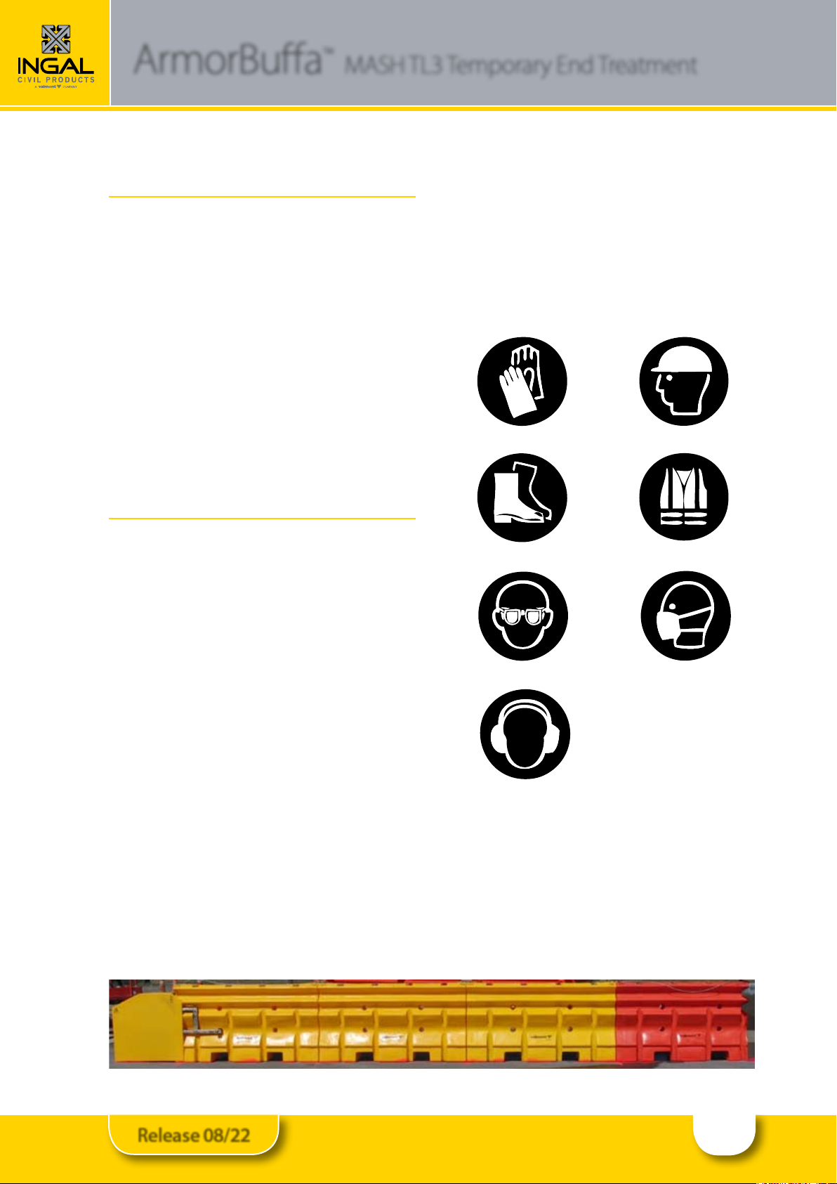
Safety Equipment
Trac Control
• Trac Control Equipment • Trac Control Plan
Gloves
Steel-Capped Footwear
Hard Hat
Safety Vest
Dust Mask
Safety Glasses
Hearing Protection
3
Release 08/22
ArmorBua™MASH TL3 Temporary End Treatment
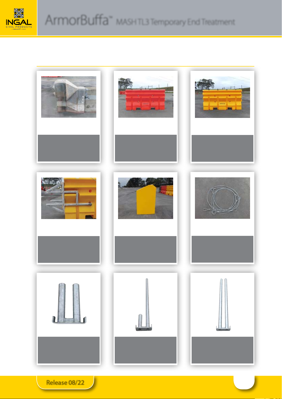
3.1 ArmorBua MASH TL3 Identication and Installation
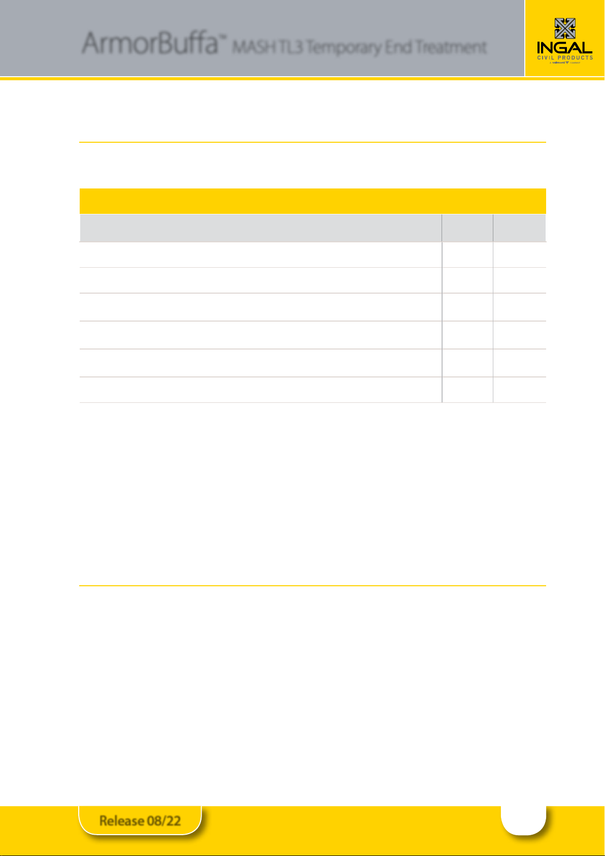
3.0 Parts Identication
Use only Ingal Civil Products parts that are specied by Ingal Civil Products for use with
the ArmorBua™ System. The use of unspecied parts is prohibited and could result in
severe personal injury or death.
PART # DESCRIPTION CONCRETE
KIT
10200320 ArmorBua Transition F-Type Concrete 1
10200322 ArmorBua Element - Orange 1
10200323 ArmorBua Element - Yellow 3
10200324 ArmorBua Steel Nose Assembly 1
10200325 ArmorBua Nose Cover 1
10200326 ArmorBua Cable 1
10200327 ArmorBua Nose Pin 1
10200328 ArmorBua Asymmetric Pin 1
10200204 ArmorZone Pin 3
10200329 ArmorBua Transition F-Type Concrete Fixing Bolt Kit 1
10200045 ArmorBua MASH TL3 F-Type Concrete Kit - Complete
10200200 Drainage Bung
10200202 Bung Spanner 1
4
Release 08/22
ArmorBua™MASH TL3 Temporary End Treatment
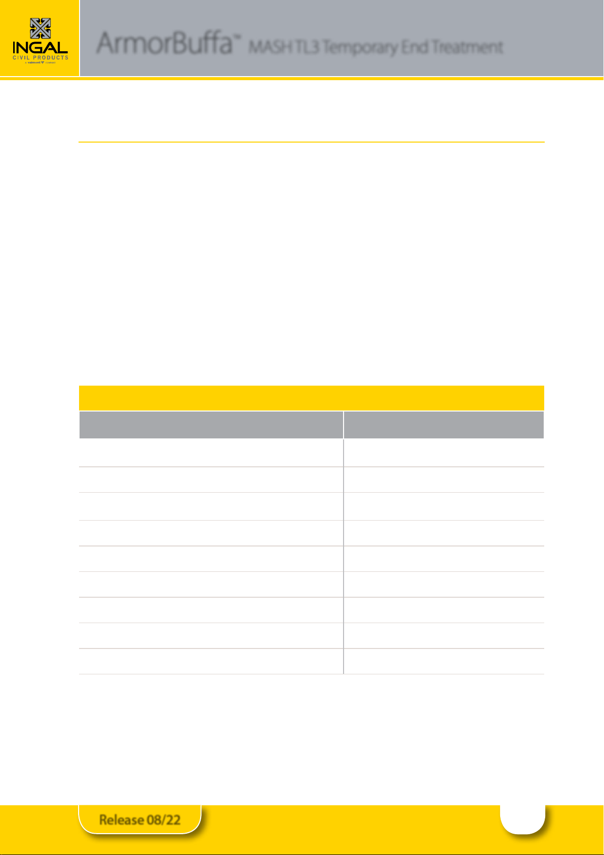
10200320
ArmorBua Transition F-Type Concrete
Concrete Kit: 1
10200204
ArmorZone Pin
Concrete Kit: 3
10200323
ArmorBua Element - Yellow
Concrete Kit: 3
10200326
ArmorBua Cable
Concrete Kit: 1
10200324
ArmorBua Steel Nose Assembly
Concrete Kit: 1
10200327
ArmorBua Nose Pin
Concrete Kit: 1
10200322
ArmorBua Element - Orange
Concrete Kit: 1
10200325
ArmorBua Nose Cover
Concrete Kit: 1
10200328
ArmorBua Asymmetric Pin
Concrete Kit: 1
3.0 Parts Identication (continued)

5
Release 08/22
ArmorBua™MASH TL3 Temporary End Treatment
10200329
ArmorBua Transition F-Type
Concrete Fixing Bolt Kit
Concrete Kit: 1
10200202
Bung Spanner
10200045
ArmorBua MASH TL3 F-Type Concrete Kit
10200200
Drainage Bung

6
Release 08/22
ArmorBua™MASH TL3 Temporary End Treatment
4.0 Preparation
4.1 Foundation
The ArmorBua™ system is designed to perform on a
variety of foundations including concrete, asphalt, and
any other surfaces capable of bearing the weight of the
system.
Uneven surfaces should be attened, and large debris
removed from the foundation prior to installation.
Cross slopes of up to 8% (5° or 1:12 slope) can be
accommodated with the standard hardware and the
instructions provided in this manual. For slopes in
excess of 8%, contact Ingal Civil Products.
4.2 Transition
ArmorBua™ is designed to accommodate a temporary
F-Type concrete barrier.
Placement and installation of the ArmorBua™
system must be accomplished in accordance with the
Austroads Design Guide and ASBAP and other state
and local standards.
Before installing the ArmorBua™ system, ensure that
all the materials required for the system are on site and
have been identied.
5.0 Documentation
Prior to installation and assembly of the ArmorBua™
system, ensure you have read and understand the
installation and assembly instructions. The following
items should be reviewed and understood prior to
installation.
Installation and Assembly Manual (check for current •
revision posted at www.ingalcivil.co.nz).
System Drawings (check www.ingalcivil.co.nz for•
current revision, located in installation manual).
6.0 Important Notes
Sign Convention•
The term Front = At the Nose Plate
The term Rear = At the Transition
This manual follows installation steps for a•
complete ArmorBua™ system that is installed on
site or relocated to another location.
See Page 16 for water lling instructions.
In regions where the water lled
elements could become frozen,
appropriate anti-freeze solutions
should be used.
Failure to do so will result in improper
performance of the system and may
cause serious bodily injury.
Care should be taken to ensure that appropriate Anti
-Freeze solutions are used in accordance with federal,
state, and local requirements.
7.0 Anchoring Specications
The ArmorBua™ system uses M16 x 150mm Excalibur™
Screw Bolts or equivalent for anchoring to temporary
concrete barrier.

7
Release 08/22
,'
'HVFULSWLRQ
3DUW1R
4W\
$UPRU%XIID7UDQVLWLRQ)7\SH&RQFUHWH
$UPRU%XIID(OHPHQW2UDQJH
$UPRU%XIID(OHPHQW<HOORZ
$UPRU%XIID6WHHO1RVH$VVHPEO\
$UPRU%XIID1RVH&RYHU
$UPRU%XIID&DEOH
$UPRU%XIID1RVH3LQ
$UPRU%XIID$V\PPHWULF3LQ
$UPRU=RQH3LQ
$UPRU%XIID7UDQVLWLRQ)7\SH&RQFUHWH)L[LQJ%ROW.LW
'=#VTJOFTT%FWFMPQNFOU=5FDIOJDBM-JCSBSZ=7BMNPOU)JHIXBZ=.FUIBOF=%SBXJOHT=.FUIBOF%SBXJOHT8*17JUPS='PS"QQSPWBM-FUUFST=
/%
-$
9%
7HPSRUDU\(QG7UHDWPHQW
$UPRU%XIIDWR--+RRNV
$50%--+
'5$:1
&+(&.('
$33529('
'5$:,1*180%(5
,7(0
&/,(17
0$7(5,$/
),1,6+
72/(5$1&(6
:KROH1XPEHUV
2QH'HFLPDO3ODFH
%HQG$QJOH
6WUDLJKWQHVV
5(9
'(6&5,37,21
$33'
'$7(
6FDOH
25,*,1$/,668(
9DOPRQW+LJKZD\7HFKQRORJ\
/HYHO%XLOGLQJ$7DODYHUD5RDG
0DFTXDULH3DUN16:$XVWUDOLD
7ZZZYDOPRQWKLJKZD\FRP
'0-%&3
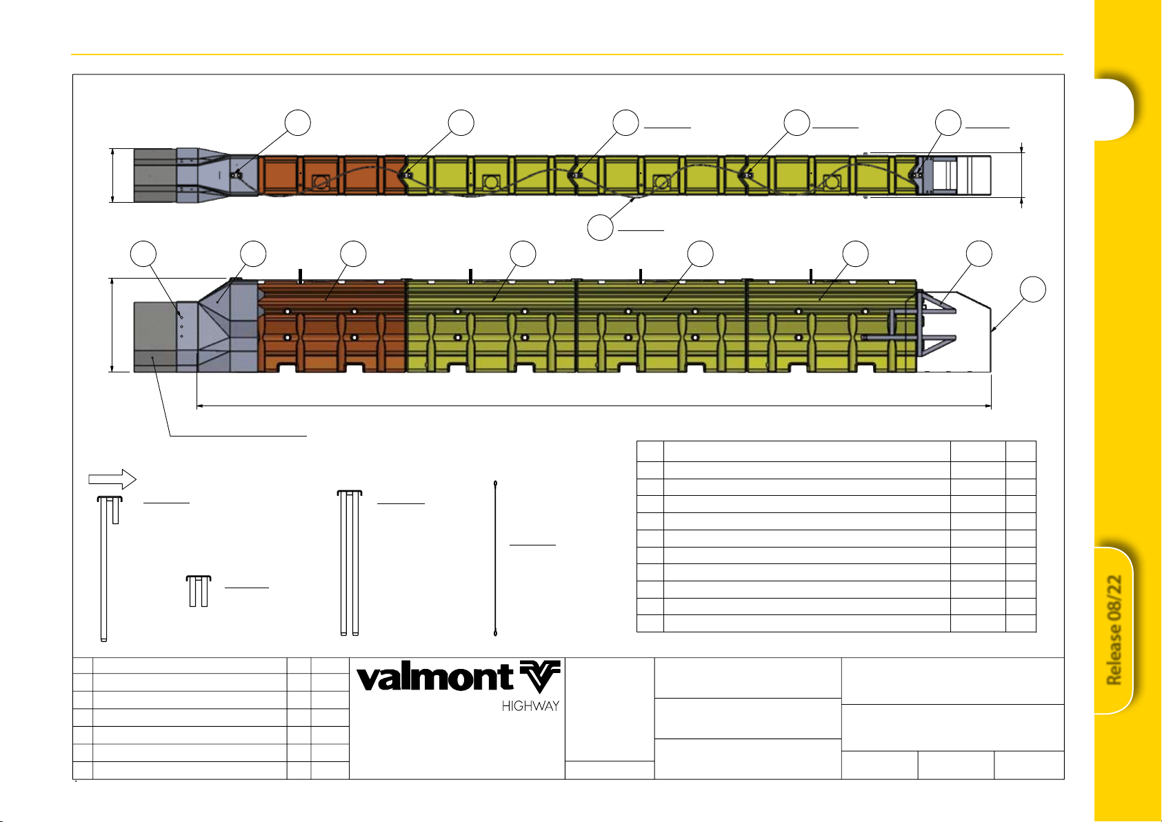
8.0 ArmorBua Exploded Assembly Overview
Important:
•AllpartsshownmustbeusedfortheArmorBuatoperformastested.
•Allpartsmustbeusedinthelocationsshown.
– Orange element must be installed into the transition.
– The 3 types of connector pins must be installed in the locations shown.
•Allelementsmustbecompletelylledwithwater.
•Allelementsmustbedrainedbeforemoving.
1
2
3
4
8
Release 08/22
9313
1100
Type-F Concrete Barrier
1 2 3 3 3 4
5
10
525
630
8 7999
6
Detail A
- Asymmetric Pin
orientation: short pin to the
front of the system.
Detail B
Nose Pin
Detail B
Detail A
Detail C
Detail C
ArmorZone Pin
Detail D
Detail D
ArmorBuffa Cable
(4x slings looped)
ID
Description
Part No.
Qty
1
ArmorBuffa Transition F-Type Concrete
10200320 1
2
ArmorBuffa Element - Orange
10200322 1
3
ArmorBuffa Element - Yellow
10200323 3
4
ArmorBuffa Steel Nose Assembly
10200324 1
5
ArmorBuffa Nose Cover
10200325 1
6
ArmorBuffa Cable
10200326 1
7
ArmorBuffa Nose Pin
10200327 1
8
ArmorBuffa Asymmetric Pin
10200328 1
9
ArmorZone Pin
10200204 3
10
ArmorBuffa Transition F-Type Concrete Fixing Bolt Kit
10200329 1
F:\Engineering\3. CURRENT DRAWINGS\COMPONENT DRAWINGS\SLDDRWs\10200045 - ArmorBua MASH TL3 F-Type Concrete Kit\
LB
JA
VB
F-Type Concrete KIT
ArmorBuffa MASH TL3
10200045
DRAWN
CHECKED
APPROVED
DRAWING NUMBER
ITEM
CLIENT
MATERIAL
FINISH
TOLERANCES
Whole Numbers :
One Decimal Place :
Bend Angle :
Straightness :
REV
DESCRIPTION
APPD
DATE
Scale:
ORIGINAL ISSUE - 23.10.2020
Valmont Highway Technology
Level 3, Building A, 11 Talavera Road
Macquarie Park, NSW 2113, Australia
T: +612 9814 1777 www.valmonthighway.com
FOLDER
8.1 ArmorBua MASH TL3 F-Type Concrete Kit

9
Release 08/22
ArmorBua™MASH TL3 Temporary End Treatment
9.0 INSTALLATION PROCEDURE
STEP 1A Transition Fixing to Concrete F-Type
INSTRUCTIONS
1. Slide transition over the end of the temporary concrete barrier, ensuring it is pushed on as far as possible ush
up against the end of the barrier. Then mark the location of the 6 holes.
2. Remove the transition and drill 6 x 16mmx150mm holes as marked. If a hole cannot be drilled due to
encountering rebar, then the use of 2 screw bolts per side is permitted.
3. Slide the transition back into place and then screw in the 2 or 3 Excalibur™ bolts per side, rmly fastening the
transition to the barrier.
Wear proper PPE when clearing debris. This operation produces concrete dust.
Gloves
Dust Mask Safety Glasses Hearing Protection

10
Release 08/22
ArmorBua™MASH TL3 Temporary End Treatment
STEP 2 Attachment to ArmorBua Elements
INSTRUCTIONS
1. Check the drain bung is tight so it will not leak.
2. Slide the orange element into the transition ensuring the element is orientated as shown in Note A with the
element end with the highest connecter lug inserted.
3. Insert standard twin pin into the transition holes, coupling the orange element and steel cable together, as
shown in Note B.
4. Slide the 3 yellow elements into position.
Note A
Note B

11
Release 08/22
ArmorBua™MASH TL3 Temporary End Treatment
STEP 3 Adding ArmorBua Elements
INSTRUCTIONS
1. Pin the 3 yellow elements with the pins as shown, engaging the steel cable.
2. The the asymmetric pin must be used to connect the yellow elements 1 and 2.
4321
12
Release 08/22
ArmorBua™MASH TL3 Temporary End Treatment
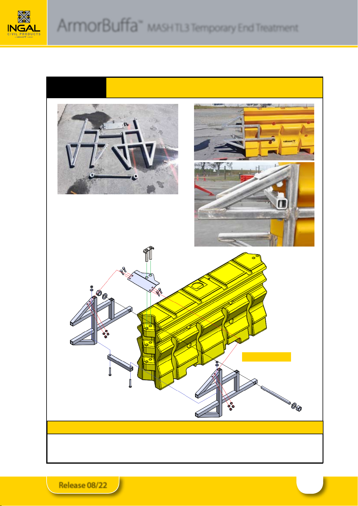
STEP 4 ArmorBua Nose Plate Assembly
INSTRUCTIONS
1. Bolt the steel nose onto the exposed end of yellow element No. 1, as shown above.
2. Tighten nuts and bolts to 50Nm.
Element No. 1

13
Release 08/22
ArmorBua™MASH TL3 Temporary End Treatment
STEP 5 ArmorBua Steel Nose Assembly
INSTRUCTIONS
1. Fit the cable through the nose pin as shown in Note A.
2. Slide the yellow plastic nose cover into position and insert the nose pin through the nose cover into the
steel nose assembly as shown in Note B. Ensuring the pin engages the cable loop.
Note A Note B
14
Release 08/22
ArmorBua™MASH TL3 Temporary End Treatment
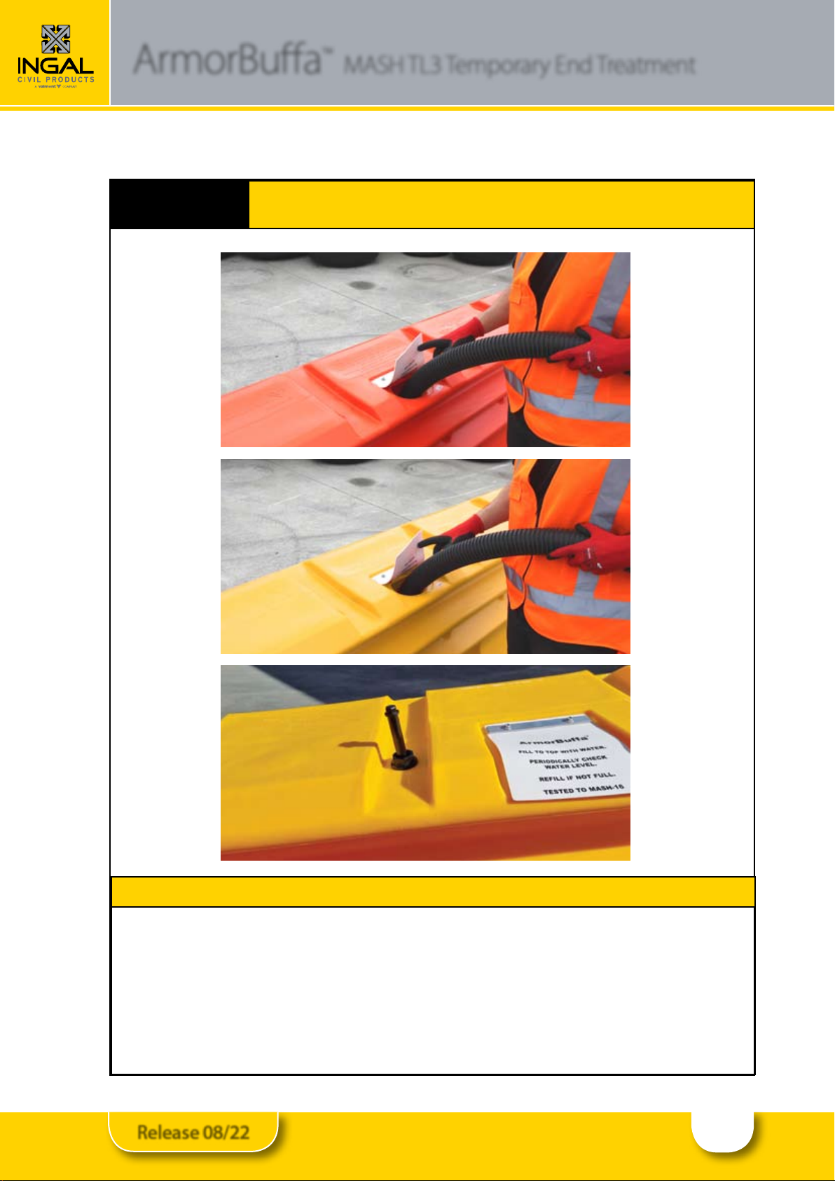
STEP 6 Final Inspection and Filling of Elements
INSTRUCTIONS
1. Inspect installed system ensuring the correct pins are in the correct locations and that the steel cable is
engaged through each pin.
2. Fill all 4 elements (1 x orange and 3 x yellow) with water to capacity (within 25mm of the top) using the
lling port, 700 litres per element.
3. Ensure the Water Fill Level Indicators are raised above the top of the element, indicating the element is
full of water.
4. Check there are no leaks in the elements or around the drain bungs.
15
Release 08/22
ArmorBua™MASH TL3 Temporary End Treatment
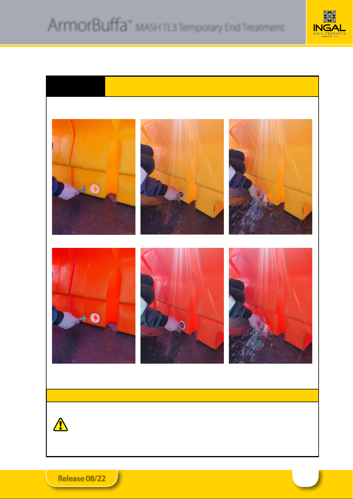
STEP 7 Disassembly and Relocation
INSTRUCTIONS
1. Drain elements by removing the bungs and then disassemble in the reverse order of assembly.
Do not stack full elements! Do not lift or move full elements!
Note: The transition can be left on the end of the temporary barrier for transportation and relocation, as
can the steel nose assembly be left on the plastic Element No. 1.
16
Release 08/22
ArmorBua™MASH TL3 Temporary End Treatment
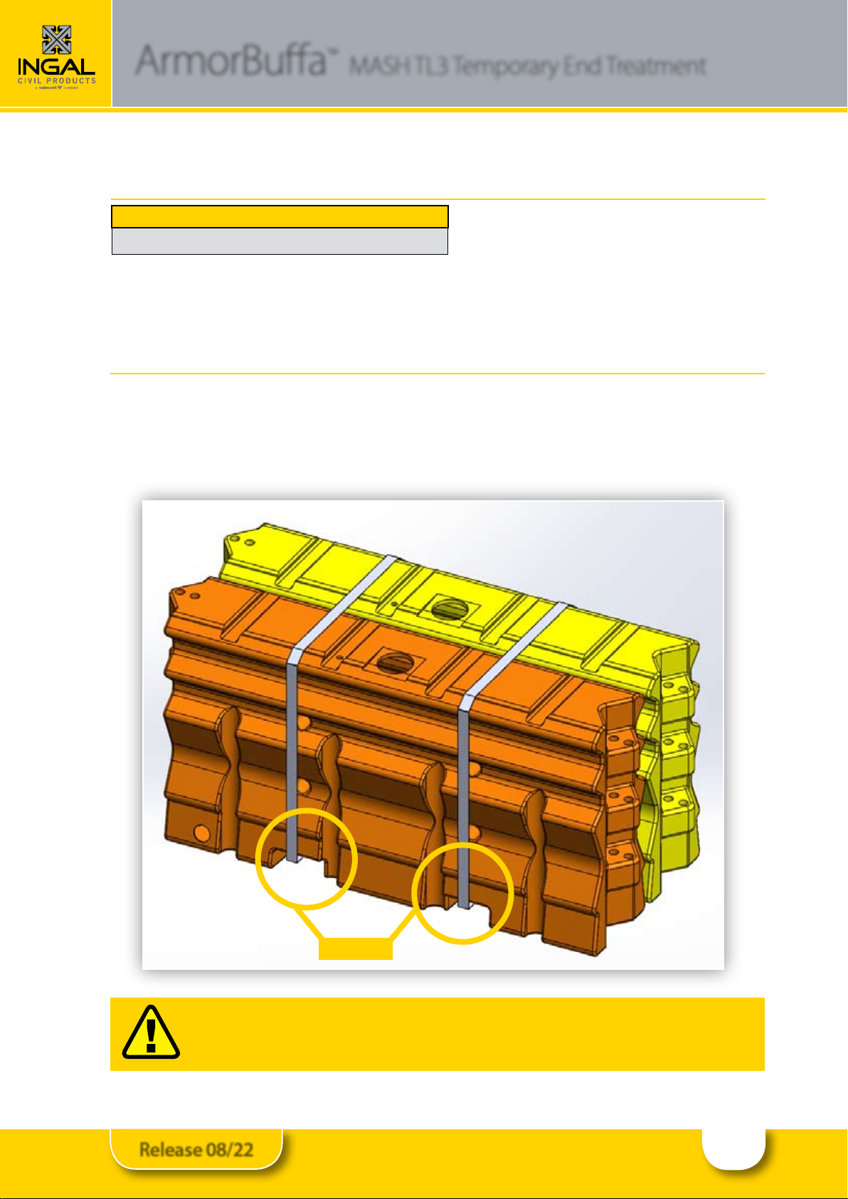
11.0 Transportation and Storage
When empty, Elements are designed to be transported and stored in strapped bundles of 2, as shown below, and can
be lifted via the forklift pockets shown in Note A.
The Transition Piece, Steel Nose Assembly and Nose Cover are to be strapped to pallets for transportation.
WARNING : Elements must be emptied before being moved or transported.
10.0 ArmorBua Element Capacity
Liquid Capacity L
700 Litres
Note A
17
Release 08/22
ArmorBua™MASH TL3 Temporary End Treatment
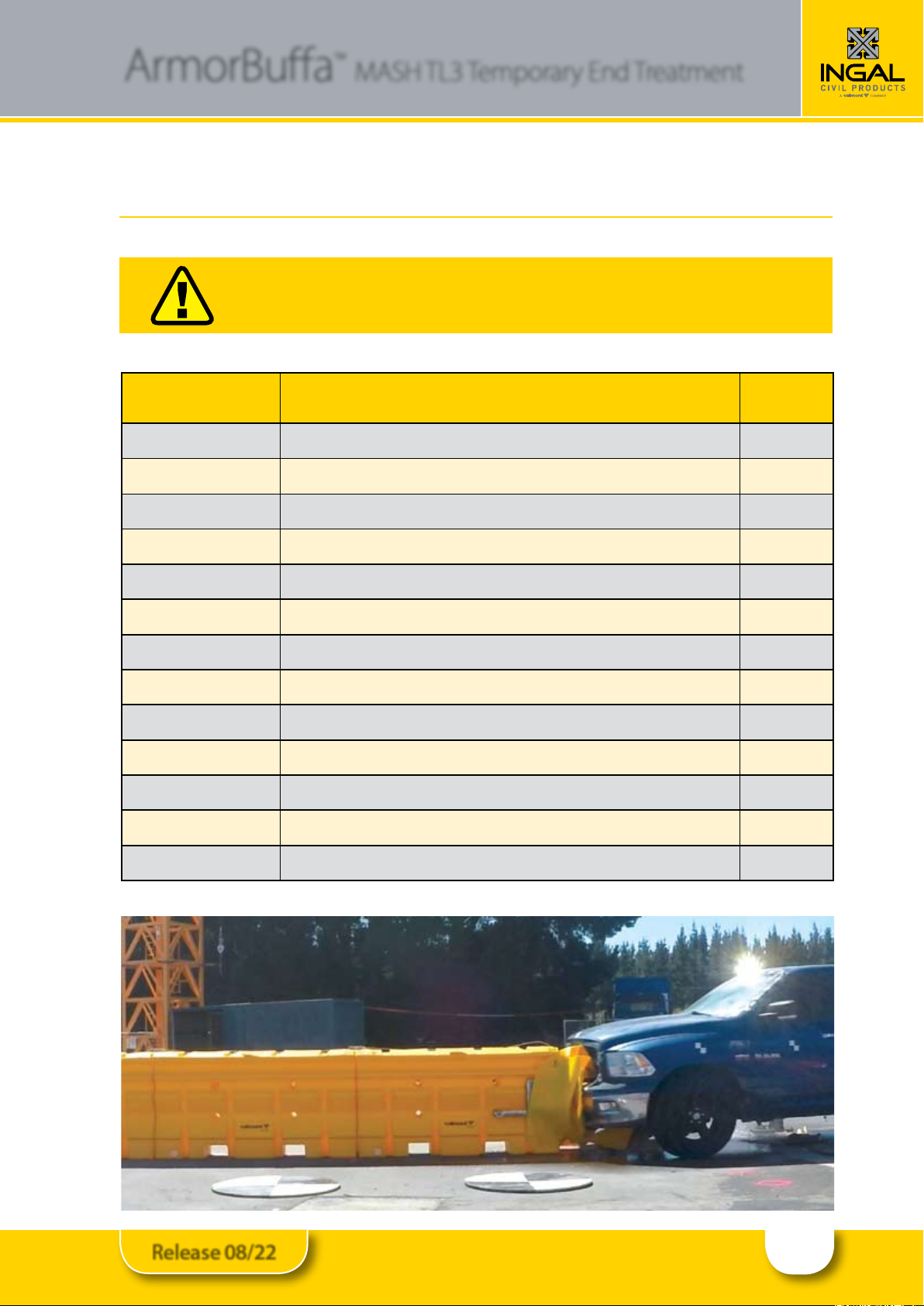
12.0 Inspector Checklist
Conrm all items in the checklist have been properly completed and hardware installed properly.
Installation Checklist
Item Date Initial
Nose Piece is rmly attached to Element No. 1.
The cable assembly is linked through each of the ve (5) connector pins.
All Elements and Nose Cover are connected with the correct pin
(refer to diagrams on pages 7, 8 and 9).
Transition is secured to the Transition Barrier with
two or three (2 or 3) M16 Anchors on each side
All Element(s) full of water and the Water Fill Level Indicators are raised
above the top of the element.
Plug at drain ports fully seated and secure with no sign of leakage.
Inspector signature: ___________________________ Date: ________________________
13.0 Maintenance Inspection
Crash cushions, like all roadside safety hardware, require inspection to ensure they are in acceptable working
condition. Regular inspections of the ArmorBua™ system is recommended and shall be made by the local highway
authority. Frequency of the inspections shall be made based on site conditions, trac volumes, and crash history.
The water level in all elements must be checked regularly. This can be done by checking that the Water Fill Level
Indicators are raised above the top of the elements. Please follow the Local guidelines for frequency of inspections to
ensure adequate repairs are made to the system. Walk-up inspections are recommended at least twice a year.
18
Release 08/22
ArmorBua™MASH TL3 Temporary End Treatment
14.0 Walk-Up Inspections
Recommended Frequency – Twice a Year
Before performing walk-up inspections, ensure trac control is deployed in accordance with local guidelines.
Check for:
Water level is within 25mm of the top of the Element’s ll ports (veried by the Water Fill Level Indicators being •
raised above the top of the elements).
Damage caused by vehicle impacts•
Damage caused by impacts from roadside maintenance equipment•
Misalignment•
Missing components•
Vandalism•
Clear and dispose of any debris in and around the system•
After inspection is complete, ensure all items identied during the inspection process are corrected.The ArmorBua™
system shall be returned to proper condition as outlined in the installation instructions.
Walk-Up Inspection
Item Comment
Water level is within 25mm of the top (check the Water Fill Level
Indicators are raised above the top of the element).
Damage caused by vehicle impacts
Minor damage caused by impacts from roadside maintenance
equipment
Misalignment
Missing components
Vandalism
Clear and dispose of any debris in and around the system
Grading around system
Fill Lids are fully seated. (Step 6, Page 16)
Inspector Signature: ____________________________________ Date: _______________________________
Print Name: ___________________________________________ Location: ____________________________
19
Release 08/22
ArmorBua™MASH TL3 Temporary End Treatment
15.0 Design Life
The design life of the ArmorBua MASH TL3 End
Treatment is 20 years. This is based on the properties
and performance of the UV stabilised HDPE and MDPE
plastic and also the hot dip galvanizing of the connector
pins, steel transition and steel nose assembly. Please
note each plastic element has a unique serial number
to enable manufacturing traceability.
16.0 Maintenance
ArmorBua™ MASH TL3 is a maintenance free system
but it is recommended that inspections are carried out
periodically to ensure that the system is installed as
required.
Over a long period of time in extreme conditions it
may be possible for evaporation to take place and it
is imperative that all the elements remain lled to the
correct level.
17.0 Recycling
The ArmorBua™ MASH TL3 End Treatment is
manufactured from UV stabilised HDPE and MDPE and
therefore the material in any units damaged beyond
repair can be recycled. The connector pins, nosepiece
and transition are manufactured from steel and can
also be recycled.

20
Release 08/22
825
250375325
1070
5
630
482
F-Type Concrete
Fixing Bolt Kit
80
Notes:
Finish = HDGalv AS/NZS 4680
(PN 10200329)
5
5
FOLDER
Valmont Highway Technology
Level 3, Building A, 11 Talavera Road
Macquarie Park, NSW 2113, Australia
T: +612 9814 1777 www.valmonthighway.com
ORIGINAL ISSUE - 23.10.2020
Scale:
DATE
APPD
DESCRIPTION
REV
Straightness :
Bend Angle :
One Decimal Place :
Whole Numbers :
TOLERANCES
FINISH
MATERIAL
CLIENT
ITEM
DRAWING NUMBER
APPROVED
CHECKED
DRAWN
10200320
ArmorBuffa Transition
F-Type Concrete
VB
JA
LB
5mm BMT G250
HDGalv
F:\Engineering\3. CURRENT DRAWINGS\COMPONENT DRAWINGS\SLDDRWs\10200320 - ArmorBua Transition F-Type Concrete\
0
1
HOLES FOR FIXING BOLTS UPDATED
JA
29/10/20
Table of contents
Other INGAL Safety Equipment manuals


Popular Safety Equipment manuals by other brands


KRATOS SAFETY
KRATOS SAFETY FA 60 034 00 manual

Clevertronics
Clevertronics L10 LWELED-IPREM Series Installation & maintenance instructions

FALL SAFE
FALL SAFE INSPECTOR General Instruction

Dräger
Dräger saver CF Series Instructions for use

Mifold
Mifold Grab-and-Go Child Restraint manual

TEUFELBERGER
TEUFELBERGER RescLoop instruction manual


