INGAL ET2000 User manual
www.ingalcivil.co.nz
Release 03/18
ET2000™ PLUS is licensed to Ingal Civil Products by Trinity Industries Inc. of the U.S.A.
Product Manual
ET2000
Guardrail Extruder Terminal
2
Release 03/18
ET2000 Guardrail Extruder Terminal
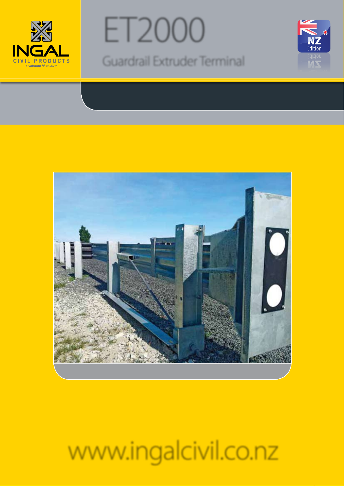
1.0 Introduction
The ET2000 Plus guardrail extruder terminal is engineered
to absorb the kinetic energy of an impacting vehicle at
a controlled rate, providing a soft ride-down for vehicle
occupants.
Unlike traditional ared guardrail terminals, the ET2000
Plus is a tangential end treatment that is installed on a
straight alignment. The use of an ET2000 Plus provides
an end treatment solution for applications where there
is insucient space for a ared end terminal or when it
is cost prohibitive to place an embankment for a ared
terminal.
The ET2000 Plus is available in two sizes. The compact
7.62m TL2 terminal is an economical solution where
the posted speed is less than or equal to 70km/h. The
standard 15.24m TL3 terminal is acceptable for all posted
speeds greater than 70km/h.
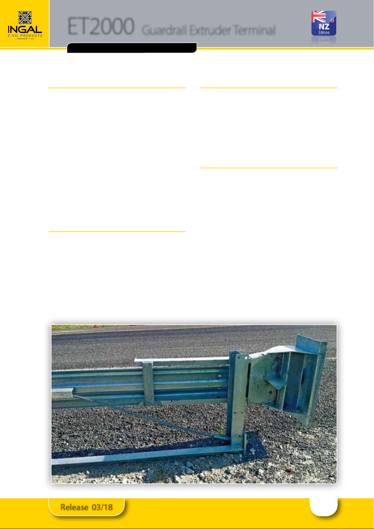
2.0 Functionality
Upon impact, the extruder head travels horizontally
along the guardrail beams, attening the w prole of the
beam and extruding the attened section away from the
trac face. It is this action that absorbs the kinetic energy
of the impacting vehicle.
The guardrail beams are supported by specially
engineered Steel Yielding Terminal (SYT) posts that are
designed to yield when the terminal is impacted end-on,
and provide redirection for side-on impacts.
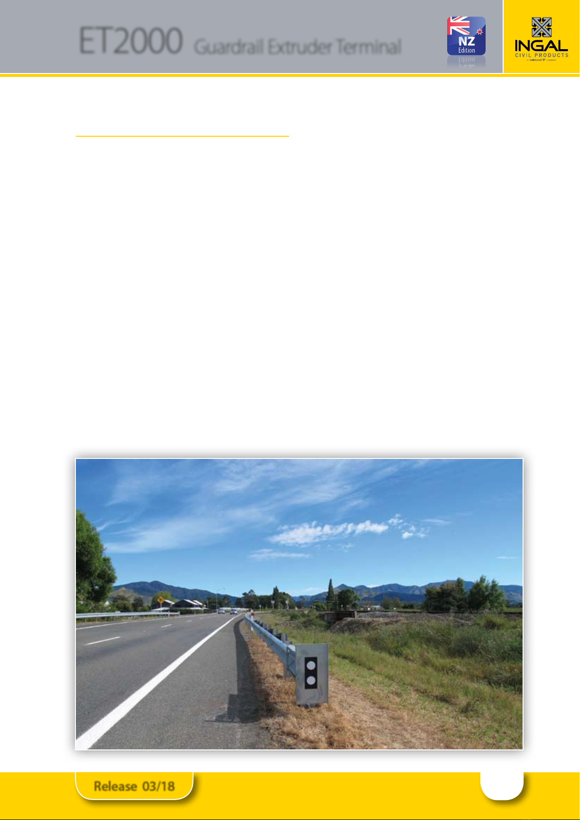
3.0 Crash Test Details
The ET2000 Plus has been crash tested and assessed in
accordance with Test Level 2 (TL2) and Test Level 3 (TL3)
of the National Cooperative Highway Research Program
(NCHRP) Report 350.
Product acceptance details are available upon request
from your local Ingal representative. Acceptance
of product variants should be conrmed prior to
installation.
4.0 Specications
4.1 Material:
Guardrail Beams: Grade 350MPa
STY Posts: ASTM A36
Blocking Pieces: Composite HDPE / crumb rubber
Delineation: Class 1A reective sheeting
Allsteelcomponents arehotdip galvanizedinaccordance
with AS/NZS 4680.
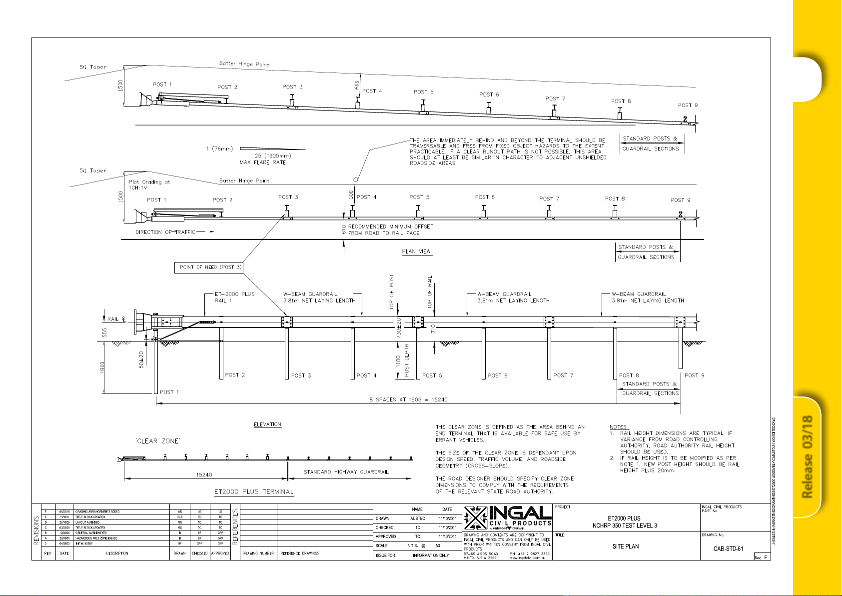
4.2 System Dimensions:
TL2 Terminal: 7.62m overall length
TL3 Terminal: 15.24m overall length
SYT Post Spacing: 1,905mm
Point of Need: Post 3
4.3 Packaging:
The ET2000 Plus is available packaged as individual units
to facilitate rapid installation and minimise disruption to
trac.
TL2 Package Mass: 330kg
TL3 Package Mass: 540kg
NCHRP350 COMPLIANT & NZTA APPROVED
3
Release 03/18
ET2000 Guardrail Extruder Terminal
5.0 Installation
Only items provided by Ingal are to be used for the
installation of the ET2000 Plus. The following written
instructions are to be read in conjunction with Ingal’s
drawings. A generic Safe Work Method Statement is
available upon request for installation operations.
5.1 Site Preparation.
The site should be prepared free of obstructing vegetation
and other hazardsthatmay interfere withthe installationor
operational performance of the system.This includes kerbs
below the system and other hazards that may hinder the
extruder head as it travels horizontally along the guardrail
beams. Some sites may require minor grading if installed
beyond the edge of the pavement shoulder.
Impacts occurring prior to the location of the 3rd post
(point of need) may allow the vehicle to pass behind the
barrier system. Therefore, the area immediately behind the
terminal should be reasonably traversable and free from
xed object hazards. If a clear run-out is not possible, this
area should be similar in character to adjacent unshielded
roadside areas.
Since the terminal functions by extruding rail away
from the trac face, a risk assessment is recommended
if pedestrians and/or cyclists will be accessing the area
behind the terminal.
5.2 Set-Out
When the downstream guardrail system is installed parallel
to the edge of the roadway without any oset, a 25:1 or
atter are over the length of the ET2000 Plus may be
used to locate the extruder head away from the roadway.
When the ET2000 Plus is installed at the end of guardrail
following a curved alignment, the following should be
adopted for the layout of the terminal. For both conditions,
the ET2000 Plus must be straight over the length of the
system. All osets are measured to the face of the rail.
Outside of the Curve. The ET2000 Plus is to be installed
with a maximum oset of 610mm from the curve.
Inside of the Curve. For a curve radius of 300m or less,
the ET2000 Plus is to be installed with a maximum oset
of 305mm from the curve. For a curve radius greater than
300m, the ET2000 Plus is to be installed with a maximum
oset of 610mm from the curve.
When establishing the post locations of the terminal, take
care to note the following;
•The rst two posts from the end of the terminal have
no oset blocking piece;
•The 200mm oset block used in the terminal is wider
than conventional w-beam oset blocking pieces.

4
Release 03/18
ET2000 Guardrail Extruder Terminal
5.3 Installing the HBA Bottom Post
The rst post of the ET2000 Plus is a Hinged Breakaway
(HBA) post that comprises a top and bottom halve.
Installation commences by rst installing the bottom half
of the post as an individual item. This may be achieved by
•Driving the bottom post with an approved driving head
to the appropriate depth, approximately 1,800mm
or
•Auguring a 300mm diameter pilot hole approximately
1,800mm deep and force the HBA post to the
appropriate depth by impact or vibratory means with
an approved driving head after compaction. Backll
material shall be placed in 150mm lifts and compacted
with pneumatic equipment or heavy hand tampering
equipment for optimal compaction.
If rock is encountered when installing the HBA bottom
post, use either of the following procedures unless there
is a more restrictive Regulatory Authority specication
that should be followed:
•If rock is encountered with less than 500mm required
to complete the installation of the HBA bottom post
to full depth, drill a 300mm diameter hole in the
rock to the depth required to install the HBA bottom
post to full depth. Backll and compact the hole in
accordance with Section 5.6.
•If rock is encountered and more than 500mm is
required to install the HBA bottom post to full depth,
drill a 300mm diameter hole 560mm deep into the
rock. Install the HBA bottom post in the hole, cutting
o the bottom of the HBA bottom post so that its top
is at the correct elevation for proper installation. Backll
and compact the hole in accordance with Section 5.6.
Care must be taken to ensure the HBA bottom post is
installed perpendicular to the nished ground level. Once
installed the HBA bottom post should not protrude more
than 100mm above the ground line.
5.4 Installing the HBA Top Post
•Install the HBA top post by aligning the holes of the
ears on the HBA top and bottom posts. Refer to Figure
1 for the correct orientation
•In the 11mm diameter holes, install 3/8” (10mm)
diameter x 2” (50mm) hex head bolt (C1625) with a
3/8” (10mm) washer (C1620) and secure with a 3/8”
(10mm) lock washer (C1622) and 3/8” (10mm) hex
nut (C1626). The bolts should be installed so that the
nuts are on the inside of the ears
•In the 21mm diameter holes, install a .” (20mm)
diameter x 2.” (63mm) hex head high strength bolt
(C1619) with a .” (20mm) washer (C1617) and secure
with a .”(20mm) lock washer (C1624) and .”(20mm) hex
nut (C1618). There is no torque requirement for these
bolts. They should be tightened to a snug position. Do
not install the bolt on the shoulder side until the strut
is ready to be installed.
The HBA Top Post must be installed perpendicular
to the nished ground level. (±1° or 15mm angular
displacement at top of post).
5.5 Installing the SYT Posts
The SYT posts may be installed by using any of the
following methods:
•Driving the posts with an approved driving head to
the appropriate elevation, 730mm ± 20mm. Note
there is little tolerance in relative height of posts to
one another. Care in setting the posts to the same
height will facilitate a quicker installation.
or
•Auguring a 300mm diameter pilot hole approximately
1,100mm deep. Backll native material shall be placed
in 150mm lifts and compacted with pneumatic
equipment or heavy hand tampering equipment
for optimal compaction. Force the SYT post into
backlled hole to an appropriate depth by impact or
vibratory means with an approved driving head.
•If rock is encountered, drill a 300mm diameter hole in
the rock to the depth required to install the SYT post to
full depth. Backll and compact the hole. The material
removed from the hole may be used for the backll.
5.6 Backll of Posts in Excavated Rock Holes
Native materials may be used for backlling in overlying
soil. Backll material in excavated rock hole should be
compliant to ASTM C33 coarse aggregate size number
57 – reference Table 1.
Figure 1: Orientation of HBA Post
Trac
Side
Table 1: Grading Requirements for Coarse Aggregate
Size
No.
Amounts ner than each laboratory
sieve (square - openings), mass percent
37.5mm 25.0mm 12.5mm 4.75mm 2.36mm
57 100 95 to 100 25 to 60 0 to 10 0 to 5

5
Release 03/18
ET2000 Guardrail Extruder Terminal
Backll material shall be placed and compacted to 95%
maximum dry density in 150mm lifts. When the top of
the drilled hole is not at the surface, the soil above the
drilled hole should consist of native soil re-compacted to
existing specications. The post should be driven into the
backlled hole after compaction.
5.7 Installing the Angle Strut
•Place the angle iron strut (C1798G) between post 1
(HBA post) and post 2 (rst SYT post).
• Attach the strut to post 1 (HBA post) with a ¾”(20mm)
diameter x 2½” (63mm) hex head high strength bolt
(C1619) with a ¾” (20mm) washer (C1617) and secure
with a ¾”(20mm) lock washer (C1624) and ¾”(20mm)
hex nut (C1618). Install so that the nut is on the inside
of the ears.
• Attach the strut to post 2 (rst SYT post) with 2 o
7/16” (11mm) diameter x 1½” (38mm) hex head bolts
(C1629) with 2 o 7/16” (11mm) washers (C1628) and
secure with 2 o 7/16” (11mm) lock washer (C1630)
and 7/16” (11mm) hex nut (C1627). Install so that the
nut is on the inside of the ange
There is no torque requirement for any of these bolts.
They should be tightened to a snug position.
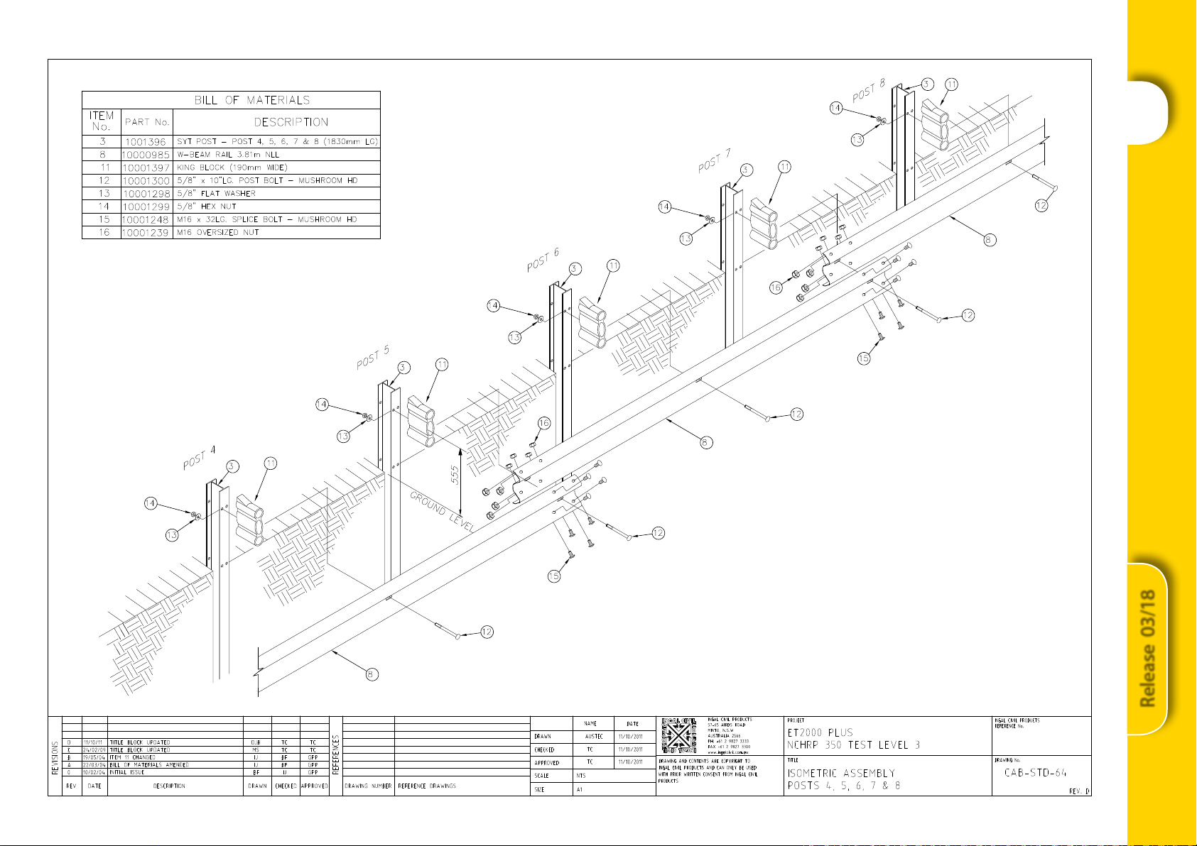
5.8 Installing Blocking Pieces and Rails
• Place the 190mm plastic King Block (C1797) on posts 3
through 8.
• Select 3 o 3.81m rail panels (C1355G) and 1 o
3.81m anchor rail (C1811G). The anchor rail should be
orientated with the anchor bracket holes closest to
the terminal end.
• At posts 3 through 8, bolt rail panels with the
correct lap orientation with a 5/8” (16mm) diameter
x 10” (255mm) long mushroom head post bolt. A
5/8”(16mm) diameter round washer (C1631) and a
5/8”(16mm) hex nut (C1632) secures the rail and block
to the post. The washer is located between the post
and the nut. See Figure 2.
• At post 2, bolt the rail panel directly to the SYT post
with a 16mm diameter x 32mm long mushroom head
post bolt (C1550) and a 16mm washer (C1631) and
hex nut (C1520). The washer is located between the
post and the nut. No post bolt is used at post 1.
• Splice the 3.81m rail panels together with eight 16mm
diameter x 32mm long mushroom head splice bolts
(C1550) and hex nuts (C1520).
Figure 2: Attachment of King Block
SYT Post (upper)
King Block
Mushroom head
post bolt with hex
nut & washer
SYT Post and King Block
SYT Post and King BlockStrut Connection at Post 1
6
Release 03/18
ET2000 Guardrail Extruder Terminal
Cable Anchor Fitting
Cable Attachment to Post 1
5.9 Installing the Cable Anchor Assembly
• The cable anchor tting (C1813G) is secured to the
anchor rail panel (C1811G) by inserting the protruding
hooks into the slots in the rail. It is locked into place by
pulling the bracket towards the terminal end.
• Slide one end of the cable (C1162) into the cable anchor
tting (C1813G) and the other end through post 1 (HBA
post). Secure the cable to the anchor tting with a 1”
(25mm) washer and 1”(25mm) hex nuts.
• Place the bearing plate (C1479G) with the 125mm
dimension up and the 75mm dimension down.
Secure the cable with a 1” (25mm) washer and 1”
(25mm) hex nut
• Restrain the cable with vice grips at the end being
tightened to avoid twisting the cable. Make sure the
nuts are tight and the cable is tightened to a tension
of 50Nm.
5.10 Installing the Extruder Head
The nal piece to attach is the extruder head:
• Place the extruder head (C1812G) over the end of the
anchor rail panel (C1811G). The extruder head can be
used on the left hand or right hand shoulder. Be sure
that the extruder is orientated with the exit slot on the
rear side of the guardrail system, so that the guardrail
is extruded away from trac.
• The extruder head should be pushed along the
anchor rail panel as far as it will go. Centre the rail in
the tail of the extruder.
• Thetopandbottomattachmentbracketsoftheextruder
head each have three holes to provide tolerance in
the installation. Choose the hole in the attachment
bracket that is closest to the predrilled hole in the post
to allow the extruder head be parallel with the W-Beam
rail. Secure the extruder head with a 3/8” (10mm)
diameter x 11⁄2 (38mm) hex head bolt (C1623) and a
3/8” (10mm) washer (C1620) and lock washer (C1621)
between the 3/8”(10mm) nut (C1626) and the post at
the top and bottom attachment brackets
• If not already xed, attach regulatory authority
approved reective/chevron sheeting (specications
dier in each state) to the face of the extruder
head. Note the orientation of the reective/chevron
sheeting may depend on what side of the road the
terminal is installed relative to.
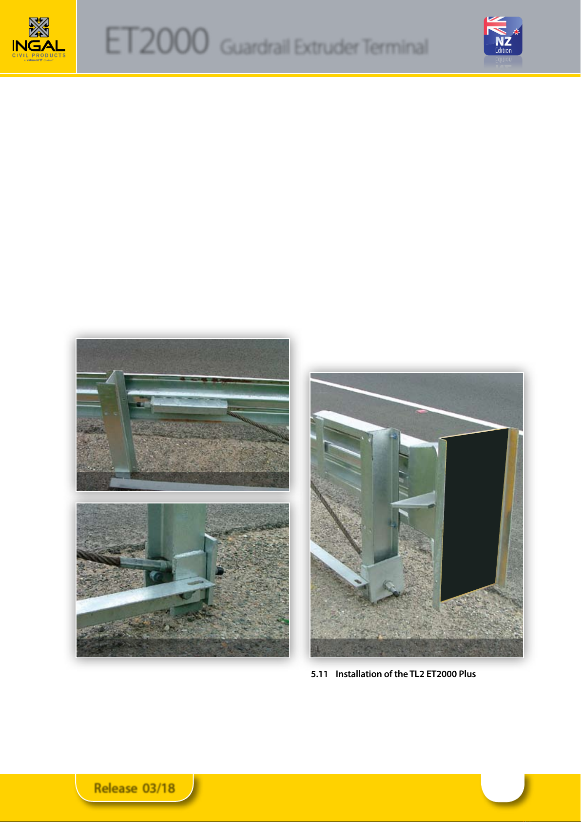
5.11 Installation of the TL2 ET2000 Plus
The installation of the TL2 system follows that of the
longer TL3 system however, the following needs to be
observed:
• The system comprises of 1 o HBA post assembly and
3 o SYT posts
Extruder Head Orientation
7
Release 03/18
ET2000 Guardrail Extruder Terminal
Ezy-Guard Smart Installation Checklist
ET2000 Plus Installation Checklist
Customer:
Project:
Barrier ID:
Terminal Type: TL2 TL3
Checked By:
Signed:
Date
Have the SYT posts been positioned every 1,905mm Yes No
Does the bottom half of post 1 (HBA) protrude not more than 100mm above ground level Yes No
Are all bolts securing the top to the bottom of the HBA post tight Yes No
Are the SYT posts at the correct height of 730mm ±20mm above ground level Yes No
Is the extruder head pushed to its maximum along the anchor rail Yes No
Is the extruder head correctly orientated with the exit slot facing the rear of the guardrail system Yes No
Is the area below the guardrails free from hazards so that the extruder head can travel freely upon impact
Yes No
Is the extruder head properly secured to post 1 through the attachment brackets Yes No
Has delineation been attached to the extruder head Yes No
Have the rails been secured to posts 2 through 8 (posts 2 through 4 for the TL2 system) Yes No
Have the rails been spliced with M16x32mm mushroom head bolts Yes No
Are all splice bolts and post bolts snug tight Yes No
Is the ll material around each post suitably compacted Yes No
Is the anchor cable secured between the anchor rail and post 1 Yes No
Is the bearing plate correctly orientated Yes No
Is the cable tensioned to 50Nm Yes No
Has any minor damage been repaired using two coats of an organic zinc rich paint Yes No
Does the terminal form a smooth line vertically and horizontally when viewed along the system Yes No
Surface Mount Variant
Has the appropriate footing been used to support the terminal, as per CAB-STD-127 or 128 Yes No
Are all anchors installed correctly without excessive bolt extending above the nut Yes No
Are all anchor nuts snug tight Yes No
Note: If the ET2000 terminal has been involved in an end-on impact, the extruder head shall be replaced.

8
Release 03/18
ET2000 Guardrail Extruder Terminal
6.0 Attachments
TheET2000Plushasbeenassessedthroughfullscalecrash
testing. The attachment of items, such as motorcycle rub
rails or handrails may alter the functionality of the terminal
as a guardrail end treatment. Only items sanctioned by
Ingal are to be attached to the ET2000 Plus.
6.1 Extruder Head Cover
Manufactured from UV stabilised Polyethylene, the
extruder cover provides protection for vulnerable road
users. The cover slides over the extruder head and can
be secured with tek screws along the sides. Retroective/
Chevron sheeting is attached directly to the face of the
cover.
6.2 Motorcyclist Protection Shield
A side impact protection shield for motorcylist
protection is also available, this shield is designed to
help reduce the risk of vulnerable road users snagging
on the extruder head when impacting from the reverse
direction. Refer drawing CAB-STD-136 for installation
detail.
7.0 Maintenance
Except for repairs due to impacts, there is virtually no
maintenance required for the system. It is recommended
that annual inspections be performed to ensure the
following;
•The terminal is appropriately delineated.
•Debris has not accumulated around the terminal that
may impede the travel of the extruder head.
•The anchor cable is taut and the nuts have not been
removed from the cable.
•The blocking pieces have not rotated.
7.1 Bush Fire Damage
All steel items used for the assembly of the ET2000 Plus
are hot dip galvanized. The performance of galvanized
coatings when subjected to res depends upon a
number of factors, such as ame duration, intensity and
the characteristics of the galvanized coating.
Typical bushre conditions may expose steel structures
to an air temperature of 800°C for periods of up to 120
seconds, however zinc coatings are generally reective
and will not absorb heat at the same rate as an uncoated
steel surface. Depending on the section thickness of
the steel, the actual steel surface temperature may not
exceed 350°C.
Typically, the bushre ame duration and intensity are
not high enough to compromise the structural strength
of the steel. The hot dip galvanized coating will also
typically remain unaected through a bushre event. If
the bushre causes damage to the galvanized surface,
then the item(s) shall be replaced.
If an item to be replaced is a post or rail, it is recommended
that the blocking pieces be replaced at these locations.
7.2 Damage Assessment
In the event of a vehicle impact, damage to the terminal
is to be assessed in accordance with Table 2.
A Safe Work Method Statement is available upon request
to assist in the safe repair of the ET2000 Plus.
Only items purchased from Ingal shall be used for the
repair of the ET2000 Plus.
When replacing posts, ensure that the disturbed
foundation material is suitably compacted prior to the
installation of replacement posts.
Motorcylist Protection Shield
Extruder Head with Cover - Rear View
Extruder Head with Cover - Front View
9
Release 03/18
ET2000 Guardrail Extruder Terminal
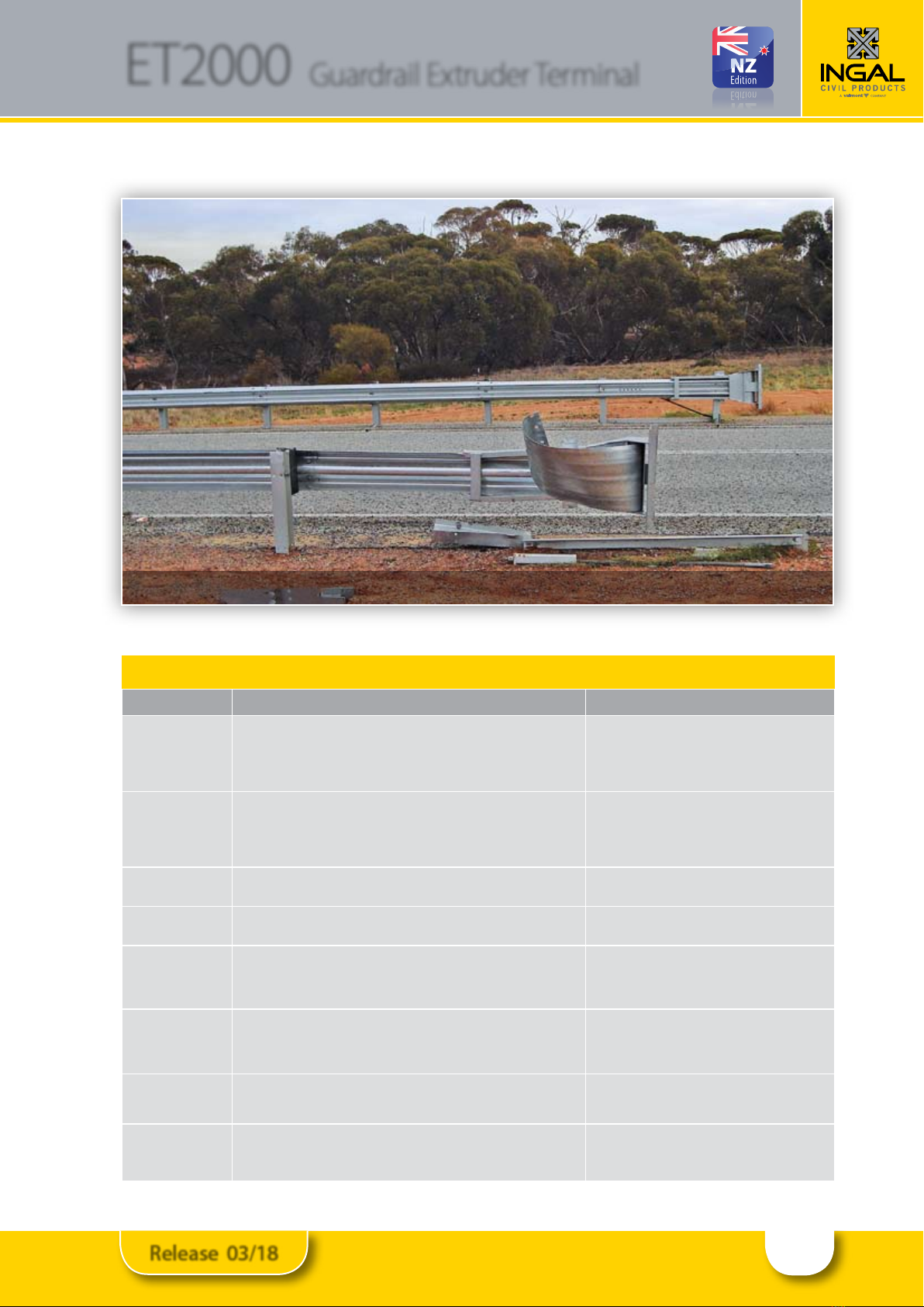
Damaged ET2000 Plus Terminal
Table 2: Damage Assessment of ET2000
Type of Defect Description of the Defect Action to be Taken
Galvanizing damage
on Posts.
The sum total of the damaged area does not exceed 45cm2(0.5% of the total surface
area) and no individual damaged area exceeds 40cm2.
The sum total of the damaged area exceeds 45cm2(0.5% of the total surface area) or
an individual damaged area exceeds 40cm2.
An organic zinc rich epoxy paint is to be applied to the
repair area in two coats.
The post is to be replaced.
Galvanizing damage
on rails.
The sum total of the damaged area does not exceed 200cm2(0.5% of the total
surface area) and no individual damaged area does not exceed 40cm2.
The sum total of the damaged area exceeds 200cm2(0.5% of the total surface area)
and/or an individual damaged area exceeds 40cm2.
An organic zinc rich epoxy paint is to be applied to the
repair area in two coats.
The rail is to be replaced.
Mechanical damage on
blocking pieces
The blocking piece has chips or cracks. The blocking piece is to be replaced.
Mechanical damage on
SYT posts.
The post is bent. The post is to be replaced.
Mechanical damage on
extruder head
The extruder head has minor damage that will not prevent its travel along the rail.
The extruder head is bent which will prevent its travel along the rail.
The delineation tape is damaged.
The extruder head may be reused.
The extruder head is to be replaced.
The delineation tape is to be replaced.
Mechanical damage
on rail.
The rail is dented, twisted or flattened.
There are nicks in any part of the rail.
The slots in the rail are distorted.
The rail is to be replaced.
The rail is to be replaced.
The rail is to be replaced.
Mechanical damage
on bolts.
The body of the bolt is distorted.
The thread of the bolt is damaged.
The bolt is to be replaced.
The bolt is to be replaced.
Disturbance of material
around posts.
The material around the post is loose or uncompacted. Any disturbed pavement or material around a post shall
be left dense, tight and smooth so that resistance to water
penetration is similar to that of the adjacent surface.
Note: If the ET2000 terminal has been involved in an end-on impact, the extruder head shall be replaced.
10
Release 03/18

11
Release 03/18

12
Release 03/18
13
Release 03/18

14
Release 03/18

15
Release 03/18

www.ingalcivil.co.nz
contact us on the web
Head Oce: Sydney
57-65 Airds Road, Minto, NSW 2566
Ph: +61 2 9827 3333
Fax: +61 2 9827 3300
Free call (within Australia):
1800 803 795
Email: [email protected]
Auckland
40 Tironui Road, Takanini
Auckland 2112 New Zealand
Ph: 0212 464 997
Email: [email protected]o.nz
For more information
Table of contents
Other INGAL Safety Equipment manuals


Popular Safety Equipment manuals by other brands

TEUFELBERGER
TEUFELBERGER hipSTAR FLEX 12,7mm Manufacturer's information and instructions for use

Spencer
Spencer Logic user manual

Storch
Storch Craftsman sun operating instructions

Rockwell Automation
Rockwell Automation Allen-Bradley GuardShield 450L-B4FNxYD user manual

ABB
ABB Jokab Safety Safeball JSTD1 Original instructions

SKYLOTEC
SKYLOTEC PEANUT Series Instructions for use


