INGAL Ezy-Guard 4 User manual
Release 07/22b
Product Manual
www.ingalcivil.com.au
Roadside Safety Barrier
2
Release 07/22b
1.0 Introduction
Introducing Ezy-Guard 4, a member of
theEzy-Guardfamily,thenextgeneration
steel guardrail barrier providing superior
motorist safety and more metres of
barrier for your dollar.
Ezy-Guard 4 is crash tested to the latest
performance standard distinguishing
it from the existing Australian public
domain guardrail barrier system.
The Z-post prole shields post edges
from vulnerable road users and provides
sectional strength when driving through
dicult conditions.
An Ezy-Carriage is used to secure the
w-beam rails to the posts eliminating
the requirement for blocking pieces
and rail stiening plates. This unique
connection provides a soft ride-down
for the occupants and smooth vehicle
containment and redirection.
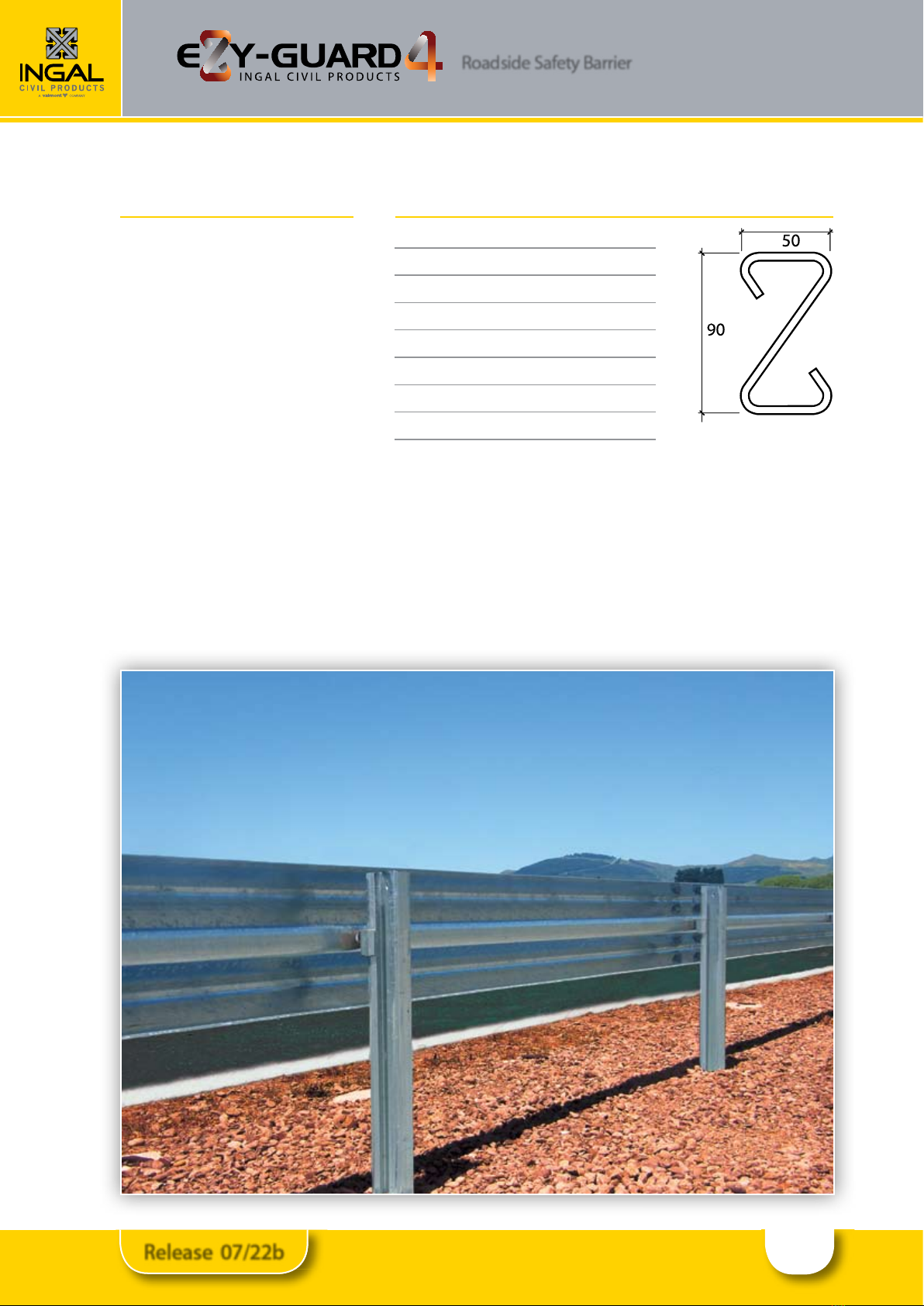
2.0 Specications
Ezy-Guard 4 Z-Post Length: 1,650mm
Ezy-Guard 4 Z-Post Mass: 12.5kg
Ezy-Guard 4 System Mass: 18.6kg per metre
Rail Height Above Ground: 787mm
Z-Post Height Above Ground: 777mm
Post Spacing: 2,000mm
Ezy-Guard 4 SystemWidth: 200mm
MASHTL3 CrashTest Deflection: 1.65m
Ezy-Guard 4 rails and Z-posts are manufactured from hot-rolled steel
at products in accordance with AS/NZS 1594. These items are hot dip
galvanised in accordance with AS/NZS 4680 after fabrication leaving no
surface untreated.
Australian state specic product acceptance details are available upon
request from your local Ingal representative. Acceptance conditions
should be conrmed prior to installation.
Roadside Safety Barrier
3
Release 07/22b
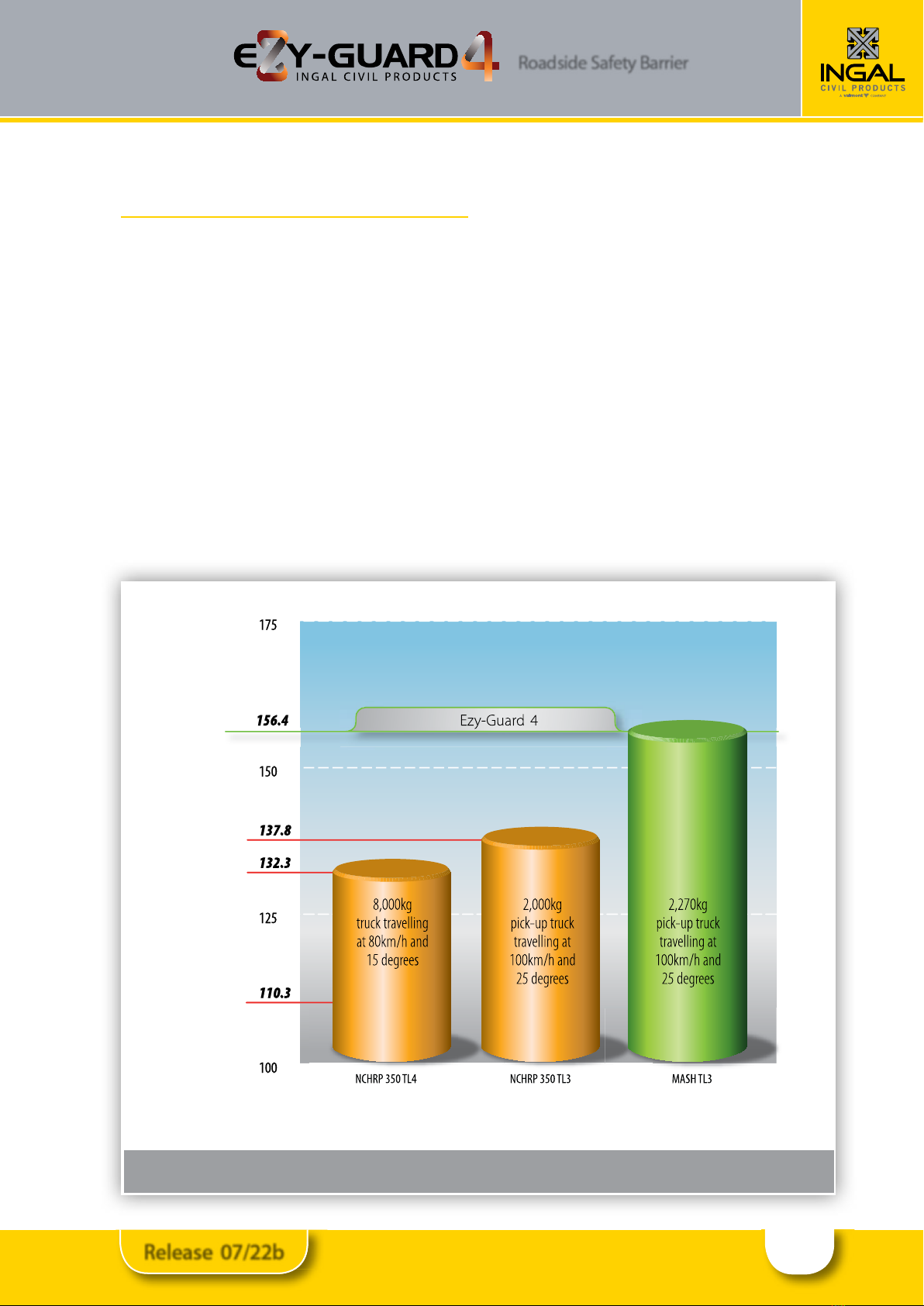
Figure 1: Comparison of Crash Test Impact Severities
3.0 Crash Test Analysis
Crash test guidelines provide a minimum set of
requirements that a roadside barrier has to meet in order
to demonstrate its satisfactory impact performance.
Whilst crash test guidelines cannot include all possible
impact conditions that may be experienced in the real
world, the crash test matrix is selected to represent a “worst
practical condition”for a roadside barrier impact.
Ezy-Guard 4 has been fully crash tested and evaluated
according to the specications for Test Level 3 (TL3) of the
AASHTO Manual for Assessing Safety Hardware (MASH).
The system has also been crash tested in accordance
with NCHRP-350 Test Level 4, this is the containment of a
8000kg truck impacting the rail at 80km/h and 15°.
The MASH specication is an update to and supersedes
NCHRP Report 350 for the purposes of evaluating new
safety hardware devices.
The MASH TL3 crash test matrix requires the following
impacts;
•1100kg car travelling at 100km/h and 25 degrees.
•2270kg pick-up travelling at 100km/h and 25 degrees.
Crash test impact conditions are dened by the mass,
speed, and angle of the impacting vehicle. Crash test
standards and performance levels can be compared by
calculating the impact severity (IS).
IS = ½ M (V sin θ)2
Where IS is the impact severity in joules (J), M is the test
inertial mass of the vehicle in kilograms (kg), V is the
impact speed in metres/second (m/s) and θ is the impact
angle in degrees.
Impact
Severity
(kJ)
Crash Test Performance Level
Note:The MASHTL4 impact
severity is 209.3kJ
Roadside Safety Barrier
4
Release 07/22b
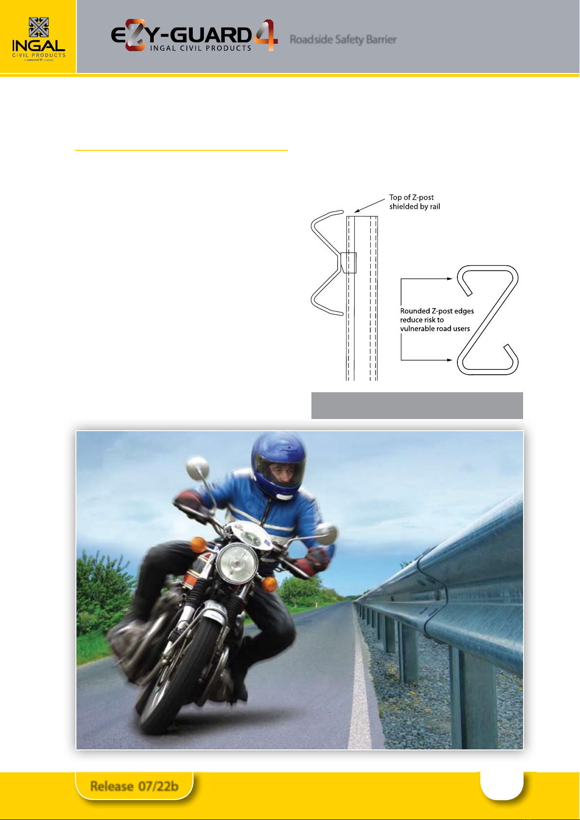
Figure 2: Ezy-Guard 4 Considerations for
Vulnerable Road Users
4.0 Consideration for Vulnerable
Road Users
Vulnerable road users include motorcyclists, pedestrians,
cyclists and other road users. Ezy-Guard 4 has been
designed to provide consideration to vulnerable road
users as follows:
Rounded Post Corners.
The Z-post contains smooth, rounded post edges and
corners mitigating the risk and severity of fractures and/
or contusions.
Energy Absorbing, Ductile Z-Posts.
The Z-posts are designed to yield by bending near
ground level. This bending action absorbs impact energy
reducing the potential for post fracturing. A fractured
or split guardrail post presents a signicant laceration
hazard to vulnerable road users.
The Ezy-Guard 4 design does not contain any elements that
become projectiles and there are no aggressive edges.
Shielded Posts.
The revolutionary design of Ezy-Guard 4 shields the top
of the supporting Z-posts by positioning the top of the
rail above the posts. This eliminates dangerous snag
points, reducing the potential for the barrier to dismount
motorcyclists or cyclists. This is a signicant safety benet
compared to all guardrail and cable barrier designs
currently used within Australia.
Roadside Safety Barrier
5
Release 07/22b
5.0 Features and Benets
5.1 Fully Compliant to MASH TL3 & NCHRP-350 TL4
Ezy-Guard 4, a member of the Ezy-Guard family, is fully
compliant to MASH TL3 and NCHRP-350 TL4.
The MASH TL3 test condition represents a 13% increase
in energy when compared to NCHRP 350 Test Level 3
impacts.
The NCHRP-350 TL4 compliance demonstrates the
systems ability to contain and redirect the large 8000kg
truck, which has a higher centre of gravity compared to
the MASH TL3 pickup truck.
5.2 Rapid Installation & Repair
Ezy-Guard 4 installation can be up to twice as fast to
install than conventional guardrail barriers and unlike
cable barrier systems, no concrete is required.
The Ezy-Guard 4 design uses fewer components and
features 1,650mm Z-posts that are rapidly driven into the
ground. The Z-post embedment depth is just 873mm, a
signicant reduction when compared to other guardrail
posts. This reduces installation time providing signicant
cost savings.
Since the Z-posts are designed to yield by bending near
ground level, damaged posts can be removed easily which
reduces the time spent by work crews on the roadside.
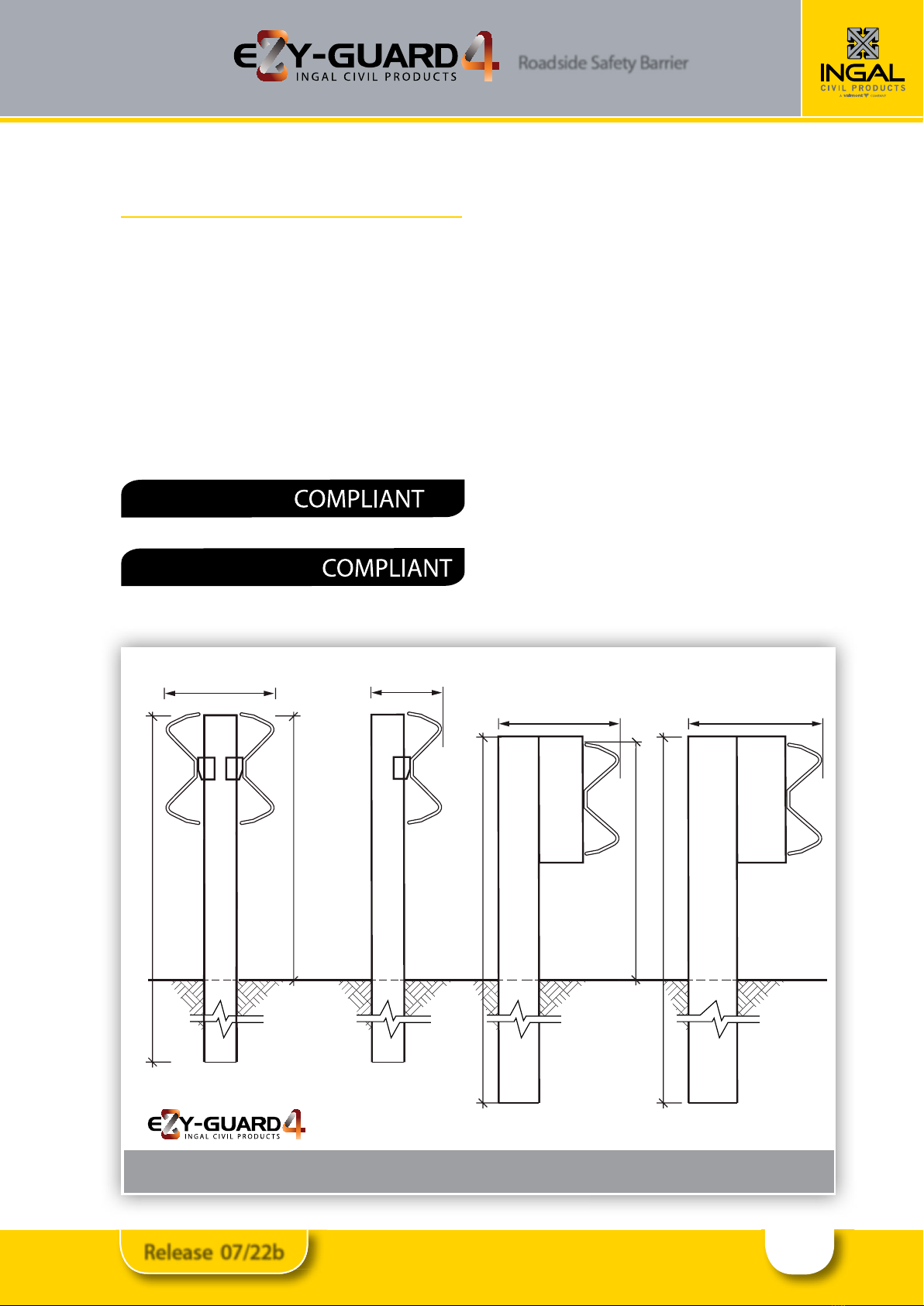
5.3 Narrow Width
With a system width of just 200mm, Ezy-Guard 4 is
signicantly narrower than traditional guardrail barriers
that incorporate the use of blocking pieces. Ezy-Guard 4
conserves valuable formation width and allows a greater
recovery width to be provided for errant vehicles.
NCHRP-350 TL4
MASH TL3
Figure 3: Ezy-Guard 4 Width Comparison
200mm
1800mm
385mm
G4 W Beam
1800mm
440mm
Type B Guardfence
Ground
surface
Double sided W-Beam
730mm
310mm
1600mm
730mm
1650mm
787mm
Other INGAL Safety Equipment manuals


Popular Safety Equipment manuals by other brands

Lanex
Lanex PB-20 instruction manual

SKYLOTEC
SKYLOTEC ANCHOR ROPES Instructions for use

Besto
Besto Buoyancy Aid 50N Instructions for use

TEUFELBERGER
TEUFELBERGER NODUS Manufacturer's information and instructions for use

Troy Lee Designs
Troy Lee Designs Tbone Product owners manual

Innova
Innova Xtirpa Instruction and safety manual

bolle SAFETY
bolle SAFETY B810 quick start guide

SHENZHEN FANHAI SANJIANG ELECTRONICS
SHENZHEN FANHAI SANJIANG ELECTRONICS A9060T instruction manual

Hiltron security
Hiltron security POWER8E Installation and use manual

Salewa
Salewa MTN SPIKE user manual

Hatco
Hatco B-950P installation guide

Sitec
Sitec TX MATIC operating manual


