INGAL ET-SS User manual

www.ingalcivil.com.au
Release 07/19
Product Manual
ET-SS
Tangent End Terminal

2
Release 07/19
ET-SS Tangent End Terminal
The ET-SS System Tangent End Terminal has been tested to American Association of State and Highway Transportation
Ocials (“AASHTO”) Manual For Assessing Safety Hardware (“MASH”) criteria, as a Test Level 1, 2, & 3 Guardrail End
Terminal.
This Manual must be available to the worker overseeing and/or assembling the product at all times. For additional
copies, contact Ingal Civil Products directly on (02) 9827 3333 or visit www.ingalcivil.com.au.
The instructions contained in this Manual supersede all previous information and Manuals. All information, illustrations,
and specications in this Manual are based on the latest ET-SS System information available from the designers of the
System to Ingal Civil Products at the time of printing. We reserve the right to make changes to this Manual at any time.
Please contact Ingal Civil Products to conrm that you are referring to the most current instructions.
Important:Theseinstructionsaretobeusedonlyinconjunctionwiththeassembly,maintenance,
and repair of the ET-SS System. These instructions are for standard assemblies specied by the
appropriate highway authority only. In the event the specied system assembly, maintenance,
or repair would require a deviation from standard assembly parameters, contact the appropriate
highway authority engineer. Ingal Civil Products representatives are available for consultation
if required.
Created May 2016
All rights in copyright reserved
www.ingalcivil.co.nz
2
www.ingalcivil.com.au
MASH TL3MASH TL2MASH TL1
3
Release 07/19
ET-SS Tangent End Terminal
Customer Service Contacts
Ingal Civil Products is committed to the highest level of customer service. Feedback regarding the ET-SS End Terminal,
its assembly procedures, supporting documentation, and performance is always welcome. Additional information can
be obtained from the contact information below:
Ingal Civil Products Corporate Contacts
Telephone 1300 446 425 (Within Australia)
+61 2 9827 3333 (International Calls)
E-mail [email protected]
Internet www.ingalcivil.com.au
Regional Telephone Contacts:
Queensland (07) 3489 9120
Western Australia (08) 9358 9139
Victoria & Tasmania (03) 9358 4100
South Australia (08) 8169 2300
Trinity Highway, in compliance with AASHTO MASH, contracts with
FHWA approved and accredited testing facilities to perform and
evaluate crash tests in accordance with AASHTO MASH.
The ET-SS System has been deemed eligible for reimbursement by FHWA
as meeting the requirements and guidelines of MASH. A component of
MASH eligibility requirements include a variety of crash tests to evaluate
product performance by simulating certain impact conditions involving
lightweight cars (approx. 1100 kg [2420 lb.]) and full size pickup trucks
(approx. 2270 kg [5000 lb.]).
The ET-SS System is tested pursuant to the test matrix criteria of MASH
as designated by AASHTO and FHWA. The FHWA AASHTO tests are not
intended to represent the performance of systems when impacted by
every vehicle type or in every impact condition existing on the roadway.
Every departure from the roadway is a unique event.
Trinity Highway expressly disclaims any warranty or liability for injury or
damage to persons or property resulting from any impact, collision or
harmful contact with its products, other vehicles, or nearby hazards or
objects by any vehicle, object or person, whether or not the products
were assembled in consultation with Trinity Highway or by third parties.
The ET-SS System is intended to be assembled, delineated, and
maintained in accordance with specic state guidelines. It is the
responsibility of the highway authority specifying the use of a highway
product to select the most appropriate product conguration for its
site specications. A highway authority’s careful evaluation of the site
layout, vehicle population type and speed, trac direction, and visibility
are some of the elements that require evaluation in the selection of a
highway product. For example, kerbs could cause an untested eect on
an impacting vehicle.
After an impact occurs, the debris from the impact must be removed
from the area immediately and the specied highway product must be
evaluated and restored to its original specied condition or replaced as
the highway authority determines as soon as possible. Product selection,
approval, proper installation, and maintenance of any highway product is
the sole responsibility of the specifying highway authority.
Safety Alert Symbols appear throughout this manual
and indicate Danger, Warning, Important or Caution.
Failure to read and follow these warnings could result
in serious injury or death.
WARNING: Do not assemble, maintain, or repair the ET-SS System
until you have read this Manual thoroughly and completely
understand it. Ensure that all Danger, Warning, Caution, and
Important statements within the Manual are completely followed.
Please call Ingal Civil Products on (02) 9827 3333 if you do not
understand any portion of these instructions or this manual.
WARNING: Safety measures incorporating appropriate trac
control devices and personal protective equipment (PPE) specied
by the highway authority must be used to protect all personnel
while at the assembly, maintenance, or repair site.
WARNING: Ensure that your assembly meets all appropriate
Manual on Uniform Trac Control Devices (“MUTCD”) and/or local
standards.
WARNING: Use only Trinity Highway or Ingal Civil parts that
are specied by Trinity Highway for use with the ET-SS System
for assembling, maintaining, or repairing the ET-SS System.
Do not utilise or otherwise comingle parts from other systems
even if those systems are other Trinity Highway systems. Such
congurations have not been tested, nor have they been approved
for use. Assembly, maintenance, or repairs using unspecied parts
or accessories is strictly prohibited. Failure to follow this warning
could result in serious injury or death in the event of a vehicle
impact with such an UNACCEPTED system.
WARNING: Do NOT modify the ET-SS System in any way.
IMPORTANT: Trinity Highway makes no recommendation whether
use or reuse of any part of the ET-SS System is appropriate or
acceptable following an impact. It is the sole responsibility
of the local highway authority and its engineers to make that
determination. It is critical that you inspect the ET-SS System
after assembly is complete to make certain that the instructions
provided in this Manual have been strictly followed.
Limitations and Warnings

4
Release 07/19
ET-SS Tangent End Terminal
1.0 Introduction
The ET-SS System is a tangent, single-sided, energy-
absorbing, redirective and gating end terminal system.
The ET-SS System is the rst end terminal to meet the
evaluation criteria set forth in the AASHTO MASH. The
ET-SS System is a 787 mm high (measured from top of
rail to nished grade) end terminal used to shield 787
mm high post w-beam guardrail.The ET-SS System may
be used to terminate post W-beam guardrail measuring
between 705 mm to 787 mm with state approved
transition (see Appendix for example).
The ET-SS System contains a ET-SS Impact Head, ET-SS
Anchor Rail, ET-SS Anchor Post (Post 0), ET-SS Angle
Strut, two (2) Steel Yielding Terminal Posts (“SYTP®”)
(Posts 1 & 2) and required hardware accessories. The
remaining length of the system beyond Post 2 uses
System Line Posts, Oset Blocks and System Rail.
Test Level 3 conguration with 3.81m panel option shown
System Rail(s)
Offset Block(s)
ET-SS
Anchor Rail
ET-SS
Impact Head
ET-SS
Anchor Paddle
System Line Post(s)
SYTP
ET-SS
Angle Strut
ET-SS
Anchor Post
(Post 0)

5
Release 07/19
ET-SS Tangent End Terminal
The ET-SS System can be assembled in a MASH Test Level 1, Test Level 2 or Test Level 3 conguration.
* Before installation, ensure the variant of highway safety barrier is accepted for use by the nal asset owner.
ET-SS Assembly Congurations
Test Level Design Speed Required System Length Posts
Test Level 3 100 km/h 15.48m Posts 0-8
Test Level 2* 70 km/h 11.67m Posts 0-6
Test Level 1* 50 km/h 7.86m Posts 0-4
Test Level 3 -15.48 m
Test Level 2 -11.67 m
Test Level 1 -7.86 m

6
Release 07/19
ET-SS Tangent End Terminal
2.0 Inspection of Shipment
Before assembling the ET-SS System, carefully unpack and inspect all components for signs of damage. Check the
received parts against the packing list supplied with the system to verify that all parts were received. If parts are
damaged or missing from the shipment or unspecied parts were part of the shipment, do not attempt to assemble
the system; contact Ingal Civil immediately.
* Before installation, ensure the variant of highway safety barrier is accepted for use by the nal asset owner.
ID COMPONENT PN TL-3 QTY TL-2 QTY* TL-1 QTY*
AET-SS Impact Head 10007538 111
BET-SS Anchor Rail 3.810 m 10007536 111
CW-Beam Rail 3.810 m 10007537 321
DET-SS Anchor Post (Post 0) 10007543 111
EET-SS SYTP® 1460 mm 10007539 111
FSYTP® Post 1830 mm 10001402 111
GSystem Line Post 1830 mm 10007540 642
HOset King Block 10001397 753
IET-SS Anchor Paddle 10007542 111
KET-SS Keeper Plate 10007545 111
LET-SS Plate Washer 10007546 111
MET-SS Anchor Angle 10007544 222
NET-SS Angle Strut 10007547 111
OM8 x 65mm Hex Bolt 10007552 222
PM8 x 40mm Hex Bolt 10007553 111
QM20 x 65mm Hex Bolt 10001286 222
RM16 x 230mm Hex Bolt 10007551 111
SM16 x 45mm Hex Bolt 10007092 111
TM16 x 250mm GR Bolt 10001300 753
UM16 x 32mm GR Bolt 10007550 32 24 16
VM25 Round Washer 10007548 111
WM20 Round Washer 10001284 444
XM16 Round Washer 10007095 444
YM8 Round Washer Wide 10007554 666
Z1”Heavy Hex Nut 10007549 111
AA M20 Heavy Hex Nut 10001285 222
BB M16 Oversize Splice Nut 10001299 41 31 21
CC M8 Hex Nut 10007555 333

7
Release 07/19
ET-SS Tangent End Terminal
ET-SS Keeper Plate
ID: K PN:10007545
ET-SS Plate Washer
ID: L PN: 10007546
ET-SS Anchor Angle
ID: M PN: 10007544
ET-SS Angle Strut
ID: N PN: 10007547
M8 x 65mm Hex Bolt
ID: O PN: 10007552
M8 x 45mm Hex Bolt
ID: P PN: 10007553
ET-SS Impact Head
ID: A PN: 10007538
ET-SS Anchor Rail 3.810 m
ID: B PN: 10007536
System Rail 3.810 m
ID: C PN: 10007537
Created May 2016
All rights in copyright reserved
www.ingalcivil.co.nz
9
ID: A
PN: 15208A
ID: B
PN: 15200G
ID: C
PN: 11G
( S lotted E nd S hown F or D etail)
SoftStop® Impact Head
SoftStop® Anchor Rail 3.810 m
System Rail 3.810 m
ID: D
PN: 15205A
ID: E
PN: 15203G
ID: F
PN: 15000G
P ost 0 P ost 1 P ost 2
SoftStop® Anchor Post
SoftStop® SYTP 1460 mm
SYTP® 1830 mm Post
ID: G
PN: 533G
ID: H
PN: 6777B
ID: I
PN: 15204A
P osts 3 - 8
System Line Post 1830 mm
Offset Block
SoftStop® Anchor Paddle
ID: K
PN: 15207G
ID: L
PN: 15206G
ID: M
PN: 15201G
SoftStop® Keeper Plate
SoftStop® Plate Washer
SoftStop® Anchor Angle
www.ingalcivil.com.au
ET-SS Anchor Post
ID: D PN: 10007543
ET-SS SYTP 1460 mm
ID: E PN: 10007539
SYTP® 1830 mm Post
ID: F PN: 10001402
System Line Post 1830 mm
ID: G PN: 10007540
Oset King Block
ID: H PN: 10001397
ET-SS Anchor Paddle
ID: I PN: 10007542
Created May 2016
All rights in copyright reserved
www.ingalcivil.co.nz
9
ID: A
PN: 15208A
ID: B
PN: 15200G
ID: C
PN: 11G
( S lotted E nd S hown F or D etail)
SoftStop® Impact Head
SoftStop® Anchor Rail 3.810 m
System Rail 3.810 m
ID: D
PN: 15205A
ID: E
PN: 15203G
ID: F
PN: 15000G
P ost 0 P ost 1 P ost 2
SoftStop® Anchor Post
SoftStop® SYTP 1460 mm
SYTP® 1830 mm Post
ID: G
PN: 533G
ID: H
PN: 6777B
ID: I
PN: 15204A
P osts 3 - 8
System Line Post 1830 mm
Offset Block
SoftStop® Anchor Paddle
ID: K
PN: 15207G
ID: L
PN: 15206G
ID: M
PN: 15201G
SoftStop® Keeper Plate
SoftStop® Plate Washer
SoftStop® Anchor Angle
www.ingalcivil.com.au
Created May 2016
All rights in copyright reserved
www.ingalcivil.co.nz
9
ID: A
PN: 15208A
ID: B
PN: 15200G
ID: C
PN: 11G
( S lotted E nd S hown F or D etail)
SoftStop® Impact Head
SoftStop® Anchor Rail 3.810 m
System Rail 3.810 m
ID: D
PN: 15205A
ID: E
PN: 15203G
ID: F
PN: 15000G
P ost 0
P ost 1 P ost 2
SoftStop® Anchor Post
SoftStop® SYTP 1460 mm
SYTP® 1830 mm Post
ID: G
PN: 533G
ID: H
PN: 6777B
ID: I
PN: 15204A
P osts 3 - 8
System Line Post 1830 mm
Offset Block
SoftStop® Anchor Paddle
ID: K
PN: 15207G
ID: L
PN: 15206G
ID: M
PN: 15201G
SoftStop® Keeper Plate
SoftStop® Plate Washer
SoftStop® Anchor Angle
www.ingalcivil.com.au
Created May 2016
All rights in copyright reserved
www.ingalcivil.co.nz
9
ID: A
PN: 15208A
ID: B
PN: 15200G
ID: C
PN: 11G
( S lotted E nd S hown F or D etail)
SoftStop® Impact Head
SoftStop® Anchor Rail 3.810 m
System Rail 3.810 m
ID: D
PN: 15205A
ID: E
PN: 15203G
ID: F
PN: 15000G
P ost 0 P ost 1 P ost 2
SoftStop® Anchor Post
SoftStop® SYTP 1460 mm
SYTP® 1830 mm Post
ID: G
PN: 533G
ID: H
PN: 6777B
ID: I
PN: 15204A
P osts 3 - 8
System Line Post 1830 mm
Offset Block
SoftStop® Anchor Paddle
ID: K
PN: 15207G
ID: L
PN: 15206G
ID: M
PN: 15201G
SoftStop® Keeper Plate
SoftStop® Plate Washer
SoftStop® Anchor Angle
www.ingalcivil.com.au
Created May 2016
All rights in copyright reserved
www.ingalcivil.co.nz
9
ID: A
PN: 15208A
ID: B
PN: 15200G
ID: C
PN: 11G
( S lotted E nd S hown F or D etail)
SoftStop® Impact Head
SoftStop® Anchor Rail 3.810 m
System Rail 3.810 m
ID: D
PN: 15205A
ID: E
PN: 15203G
ID: F
PN: 15000G
P ost 0 P ost 1 P ost 2
SoftStop® Anchor Post
SoftStop® SYTP 1460 mm
SYTP® 1830 mm Post
ID: G
PN: 533G
ID: H
PN: 6777B
ID: I
PN: 15204A
P osts 3 - 8
System Line Post 1830 mm
Offset Block
SoftStop® Anchor Paddle
ID: K
PN: 15207G
ID: L
PN: 15206G
ID: M
PN: 15201G
SoftStop® Keeper Plate
SoftStop® Plate Washer
SoftStop® Anchor Angle
www.ingalcivil.com.au
Created May 2016
All rights in copyright reserved
www.ingalcivil.co.nz
10
ID: N
PN: 15202G
ID: O
PN: 105285G
ID: P
PN: 105286G
SoftStop® Angle Stru t
5/ 16” x 2.5” Hex Bolt
5/ 16” x 1.5” Hex Bolt
ID: Q
PN: 3717G
ID: R
PN: 4489 G
ID: S
PN: 339 1G
3/ 4” x 2.5” Hex Bolt
5/ 8” x 9 ” Hex Bolt
5/ 8” x 1.75” Hex Bolt
ID: T
PN: 3500G
ID: U
PN: 3360G
ID: V
PN: 49 02G
5/ 8” x 10” GR Bolt
5/ 8” x 1.25” GR Bolt
1” Rou ndWasher
ID: W
PN: 3701G
ID: X
PN: 4372G
ID: Y
PN: 3240G
3/ 4” Rou nd Washer
5/ 8” Rou nd Washer
5/ 16” Rou nd Washer Wide
www.ingalcivil.com.au
Created May 2016
All rights in copyright reserved
www.ingalcivil.co.nz
9
ID: A
PN: 15208A
ID: B
PN: 15200G
ID: C
PN: 11G
( S lotted E nd S hown F or D etail)
SoftStop® Impact Head
SoftStop® Anchor Rail 3.810 m
System Rail 3.810 m
ID: D
PN: 15205A
ID: E
PN: 15203G
ID: F
PN: 15000G
P ost 0 P ost 1 P ost 2
SoftStop® Anchor Post
SoftStop® SYTP 1460 mm
SYTP® 1830 mm Post
ID: G
PN: 533G
ID: H
PN: 6777B
ID: I
PN: 15204A
P osts 3 - 8
System Line Post 1830 mm
Offset Block
SoftStop® Anchor Paddle
ID: K
PN: 15207G
ID: L
PN: 15206G
ID: M
PN: 15201G
SoftStop® Keeper Plate
SoftStop® Plate Washer
SoftStop® Anchor Angle
www.ingalcivil.com.au
Created May 2016
All rights in copyright reserved
www.ingalcivil.co.nz
9
ID: A
PN: 15208A
ID: B
PN: 15200G
ID: C
PN: 11G
( S lotted E nd S hown F or D etail)
SoftStop® Impact Head
SoftStop® Anchor Rail 3.810 m
System Rail 3.810 m
ID: D
PN: 15205A
ID: E
PN: 15203G
ID: F
PN: 15000G
P ost 0
P ost 1
P ost 2
SoftStop® Anchor Post
SoftStop® SYTP 1460 mm
SYTP® 1830 mm Post
ID: G
PN: 533G
ID: H
PN: 6777B
ID: I
PN: 15204A
P osts 3 - 8
System Line Post 1830 mm
Offset Block
SoftStop® Anchor Paddle
ID: K
PN: 15207G
ID: L
PN: 15206G
ID: M
PN: 15201G
SoftStop® Keeper Plate
SoftStop® Plate Washer
SoftStop® Anchor Angle
www.ingalcivil.com.au
Created May 2016
All rights in copyright reserved
www.ingalcivil.co.nz
9
ID: A
PN: 15208A
ID: B
PN: 15200G
ID: C
PN: 11G
( S lotted E nd S hown F or D etail)
SoftStop® Impact Head
SoftStop® Anchor Rail 3.810 m
System Rail 3.810 m
ID: D
PN: 15205A
ID: E
PN: 15203G
ID: F
PN: 15000G
P ost 0 P ost 1
P ost 2
SoftStop® Anchor Post
SoftStop® SYTP 1460 mm
SYTP® 1830 mm Post
ID: G
PN: 533G
ID: H
PN: 6777B
ID: I
PN: 15204A
P osts 3 - 8
System Line Post 1830 mm
Offset Block
SoftStop® Anchor Paddle
ID: K
PN: 15207G
ID: L
PN: 15206G
ID: M
PN: 15201G
SoftStop® Keeper Plate
SoftStop® Plate Washer
SoftStop® Anchor Angle
www.ingalcivil.com.au

8
Release 07/19
ET-SS Tangent End Terminal
M20 Round Washer
ID: W PN: 10001284
M16 Round Washer
ID: X PN: 10007095
M8 Round Washer Wide
ID: Y PN: 10007554
M8 Hex Nut
ID: CC PN: 10007555
M20x 65mm Hex Bolt
ID: Q PN: 10001286
M16 x 230mm Hex Bolt
ID: R PN: 10007551
M16 x 45mm Hex Bolt
ID: S PN: 10007092
M16 x 250mm GR Bolt
ID: T PN: 10001300
M16 x 32mm GR Bolt
ID: U PN: 10007550
M25 Round Washer
ID:V PN: 10007548
1”Heavy Hex Nut
ID: Z PN: 10007549
M20 Heavy Hex Nut
ID: AA PN: 10001285
M16 Oversize Splice Nut
ID: BB PN: 10001299
Created May 2016
All rights in copyright reserved
www.ingalcivil.co.nz
11
ID: Z
PN: 39 08G
ID: AA
PN: 3704G
ID: BB
PN: 3340G
1” Heav y Hex Nu t
3/ 4" Heav y Hex Nu t
5/ 8” GR Hex Nu t
ID: CC
PN: 3245G
5/ 16” Hex Nu t
www.ingalcivil.com.au
Created May 2016
All rights in copyright reserved
www.ingalcivil.co.nz
11
ID: Z
PN: 39 08G
ID: AA
PN: 3704G
ID: BB
PN: 3340G
1” Heav y Hex Nu t
3/ 4" Heav y Hex Nu t
5/ 8” GR Hex Nu t
ID: CC
PN: 3245G
5/ 16” Hex Nu t
www.ingalcivil.com.au
Created May 2016
All rights in copyright reserved
www.ingalcivil.co.nz
11
ID: Z
PN: 39 08G
ID: AA
PN: 3704G
ID: BB
PN: 3340G
1” Heav y Hex Nu t
3/ 4" Heav y Hex Nu t
5/ 8” GR Hex Nu t
ID: CC
PN: 3245G
5/ 16” Hex Nu t
www.ingalcivil.com.au
Created May 2016
All rights in copyright reserved
www.ingalcivil.co.nz
10
ID: N
PN: 15202G
ID: O
PN: 105285G
ID: P
PN: 105286G
SoftStop® Angle Stru t
5/ 16” x 2.5” Hex Bolt
5/ 16” x 1.5” Hex Bolt
ID: Q
PN: 3717G
ID: R
PN: 4489 G
ID: S
PN: 339 1G
3/ 4” x 2.5” Hex Bolt
5/ 8” x 9 ” Hex Bolt
5/ 8” x 1.75” Hex Bolt
ID: T
PN: 3500G
ID: U
PN: 3360G
ID: V
PN: 49 02G
5/ 8” x 10” GR Bolt
5/ 8” x 1.25” GR Bolt
1” Rou ndWasher
ID: W
PN: 3701G
ID: X
PN: 4372G
ID: Y
PN: 3240G
3/ 4” Rou nd Washer
5/ 8” Rou nd Washer
5/ 16” Rou nd Washer Wide
www.ingalcivil.com.au
Created May 2016
All rights in copyright reserved
www.ingalcivil.co.nz
10
ID: N
PN: 15202G
ID: O
PN: 105285G
ID: P
PN: 105286G
SoftStop® Angle Stru t
5/ 16” x 2.5” Hex Bolt
5/ 16” x 1.5” Hex Bolt
ID: Q
PN: 3717G
ID: R
PN: 4489 G
ID: S
PN: 339 1G
3/ 4” x 2.5” Hex Bolt
5/ 8” x 9 ” Hex Bolt
5/ 8” x 1.75” Hex Bolt
ID: T
PN: 3500G
ID: U
PN: 3360G
ID: V
PN: 49 02G
5/ 8” x 10” GR Bolt
5/ 8” x 1.25” GR Bolt
1” Rou ndWasher
ID: W
PN: 3701G
ID: X
PN: 4372G
ID: Y
PN: 3240G
3/ 4” Rou nd Washer
5/ 8” Rou nd Washer
5/ 16” Rou nd Washer Wide
www.ingalcivil.com.au
9
Release 07/19
ET-SS Tangent End Terminal
Documentation
• AssemblyManual(MostCurrentVersion)
• SystemDrawing(MostCurrentVersion)
Personal protective equipment (PPE)
• SafetyGlasses
• WorkGloves
• Safety-ToeShoes
• BackProtection
• HardHat
• ReectiveVest
• HearingProtection
Miscellaneous
• TracControlEquipment
• SAECombinationWrenchSet
• SocketSet&SocketWrench
• Hammer
• ChalkLine
• TapeMeasure
• MarkingPaintandPen
• StraightEdge
• Level
• PlumbLine
• PostPounder(commonlyusedfordrivingposts)
• Auger
• SoilTamper
• 5/8”AlignmentTool(DriftPin)
• LockingPliers
• C-Clamps
The ET-SS System is a tangent, single-sided, energy-absorbing, redirective and gating end terminal system that state/
specifying agency specify for use as specied by the appropriate state/specifying authority in conjunction with W-beam
guardrail on the shoulder or median of a roadway. The decision to specify the ET-SS System for a particular project is the
responsibility of the state/specifying agency design engineer who must ensure that the most appropriate end terminal
has been selected for the specic site conditions.
Important: Do not attach the ET-SS System directly to a rigid barrier (i.e. concrete barrier, wall or bridge
pier) without the use of a state/specifying agency approved transition.
Important: Ensure that the ET-SS System assembly conforms to the local road design standards.
Important: Ingal Civil Products does not direct grading. Proper site grading must be accomplished
before assembly of the ET-SS System in accordance with road controlling guidelines and requirements.
Failure to follow this warning could result in serious injury or death in the event of a vehicle impact or
collision.
3.0 Recommended Tools
4.0 ET-SS System Site Preparation
Note: The above list of tools is a general recommendation only and should not be considered an exhaustive list.
Depending on specic site conditions and the complexity of the assembly (or repair) specied by the appropriate
highway authority, additional or fewer tools may be required. Decisions as to what tools are needed to perform the job
are entirely within the discretion of the specifying highway authority and the authority’s selected contractor performing
the assembly of the system at the authority’s specied site.

10
Release 07/19
ET-SS Tangent End Terminal
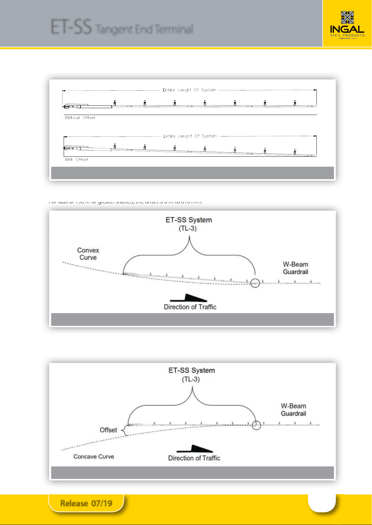
5.0 ET-SS System Oset Requirements
The ET-SS System is a tangent guardrail end treatment
that is assembled parallel to the edge of shoulder. At
the sole discretion of the state/specifying agency design
engineer, the ET-SS System may be oset away from the
shoulder over the length of the entire system (from centre
of last splice location of ET-SS System to center of Post 0)
per the following designer approved osets:
Test Level 1
(TL-1)
Test Level 2
(TL-2)
Test Level
3(TL-3)
152 mm
Maximum
305 mm
Maximum
610 mm
Maximum
Caution: Under no circumstances shall the
rail within the ET-SS System be curved.
5.1 Oset Requirements Within A Curve
When the guardrail is terminated within a curve (convex
or concave) and a ET-SS System is attached, the following
instructions must be followed to ensure proper oset
requirements within a curve for the ET-SS System are
met. If the conditions below cannot be achieved, it is
recommended that the guardrail be extended past
the curve until the conditions can be met. The oset
requirements in a curve are calculated for the TL-3 ET-
SS System. If assembling a TL-1 or TL-2 ET-SS System,
an overall straight length of 15.48 m must be obtained
(ET-SS System + W-Beam Guardrail) for calculating oset
requirements in a curve.
Note: Using an oset closer to 0 m on tighter curves
(radii) will cause the terminal to encroach on to the
shoulder.
Figure 1: Preferred Grading (not to scale)
Figure 2: Alternative Grading (not to scale)
11
Release 07/19
ET-SS Tangent End Terminal
5.2 Convex Curve
Forradiiof198morgreater(atter),theosetis0mto610mm.
5.3 Concave Curve
Forradiibetween152mand228m,theosetis0mto457mm.Forradiigreater(atter)than228m,theosetis0m
to 610 mm.
Figure 3: Entire Length of System
Concave Curve
For
radii
of
198
m
or
greater
(atter),
the
oset
is
0
m
to
610
mm.
5.3
to 610 mm.
Figure 4: Convex curve
Figure 5: Concave curve

12
Release 07/19
ET-SS Tangent End Terminal
6.0 ET-SS System Post Placement
Danger: Ensure all above & below ground
utilities are located,marked and identied
prior to using auger or post driving
equipment in accordance with local
specifying agency guidelines. Failure to
follow this warning could result in serious
injury or death.
6.1 Determine Post Locations
Place a level or straight edge on the face of downstream
guardrail (i.e. trac side) to the nished grade to create a
reference line for face of guardrail. The reference line will
be used to determine post location for the last post of
the ET-SSSystem.
The last post of the ET-SS System will be located 272 mm
from face of downstream guardrail to back of the last
post of the ET-SS System to accommodate an 190mm
oset block and be spaced 1905 mm (typical) on center
from the rst post of the W-beam system (see drawing
below). Refer to the post placement diagrams in this
manual for remaining post locations.
The ET-SS System posts may be inserted into the soil
using an auger or impact hammer pile driver used for the
placement of guardrail posts. If an auger is used, ensure
diameter is large enough to allow for proper compaction
of agency approved ll material. All ET-SS System posts
are to be assembled plumb. Proper compaction must
be accomplished for all posts in accordance with state/
specifying agency guidelines.
If rock is encountered at post locations 2-8, refer to the
local specifying agency guidelines and the AASHTO
Roadside Design Guide for requirements for embedment
depth into the rock and size of the hole. If rock is
encountered at post locations 0-1, auger a hole in the
rock large enough for full post embedment and proper
compaction of approved ll material.
If rigid pavement (e.g. concrete or asphalt) of any
thickness is encountered at post locations 0-8, ensure
a proper “leave-out” area is provided around the posts ,
refer Figures 6 and 7. This is lled with road controlling
agency approved backll material.
*Grout ll material must have a 28-day compressive
strength of 120 psi (0.85 MPa) or less.
Figure 6: Post locations

13
Release 07/19
ET-SS Tangent End Terminal
Created May 2016
All rights in copyright reserved
www.ingalcivil.co.nz
18
The SoftStop®System posts may b e inserted into the soil u sing an au ger or post pou nding eq u ipment
u sed for the placement of gu ardrail posts. If an au ger is u sed, ensu re diameter is large enou gh to allow
for proper compaction of state/ specifying agency approv ed fill material. All SoftStop®System posts are
to b e assemb led plu mb . Proper compaction mu st b e accomplished for all posts in accordance w ith
state/ specifying agency gu idelines.
If rock is encou ntered at post locations 2-8, refer to the local specifying agency gu idelines and the
AASHTO Roadside Design Gu ide for req u irements for emb edment depth into the rock and siz e of the
hole. If rock is encou ntered at post locations 0-1, au ger a hole in the rock large enou gh for fu ll post
emb edment and proper compaction of approv ed fill material.
If rigid pav ement ( e.g. concrete or asphalt) of any thickness is encou ntered at post locations 0- 8, ensu re
a proper “ leav e-ou t” area ( the specified siz e of open space as defined in the AASHTO Roadside Design
Gu ide) is prov ided arou nd the posts and filled w ith state/ specifying agency approv ed b ackfill material.
* Grou t fill material mu st hav e a 28-day compressiv e strength of 120 psi ( 0.85 MPa) or less.
D rawing S ource: AAS H T O R oadside D esign G uide, 4
th
E dition 2011
Steel Post Detail
Section A- A
www.ingalcivil.com.au
Figure 7: Steel Post Detail
Created May 2016
All rights in copyright reserved
www.ingalcivil.co.nz
18
The SoftStop®System posts may b e inserted into the soil u sing an au ger or post pou nding eq u ipment
u sed for the placement of gu ardrail posts. If an au ger is u sed, ensu re diameter is large enou gh to allow
for proper compaction of state/ specifying agency approv ed fill material. All SoftStop®System posts are
to b e assemb led plu mb . Proper compaction mu st b e accomplished for all posts in accordance w ith
state/ specifying agency gu idelines.
If rock is encou ntered at post locations 2-8, refer to the local specifying agency gu idelines and the
AASHTO Roadside Design Gu ide for req u irements for emb edment depth into the rock and siz e of the
hole. If rock is encou ntered at post locations 0-1, au ger a hole in the rock large enou gh for fu ll post
emb edment and proper compaction of approv ed fill material.
If rigid pav ement ( e.g. concrete or asphalt) of any thickness is encou ntered at post locations 0- 8, ensu re
a proper “ leav e-ou t” area ( the specified siz e of open space as defined in the AASHTO Roadside Design
Gu ide) is prov ided arou nd the posts and filled w ith state/ specifying agency approv ed b ackfill material.
* Grou t fill material mu st hav e a 28-day compressiv e strength of 120 psi ( 0.85 MPa) or less.
D rawing S ource: AAS H T O R oadside D esign G uide, 4
th
E dition 2011
Steel Post Detail
Section A- A
www.ingalcivil.com.au
Figure 8: Section A-A
Figure 9: ET-SS System (Test Level 3) – Post Placement Diagram
Notes:
1. Post 0-8 part of ET-SS System TL3
2. Post 9 is rst post of longitudinal w-beam system (not included with ET-SS System)
3. Spacing between posts is on centre as shown
4. All ET-SS System posts must be installed plumb
5. Guardrail splice joint located at Post 9
14
Release 07/19
ET-SS Tangent End Terminal
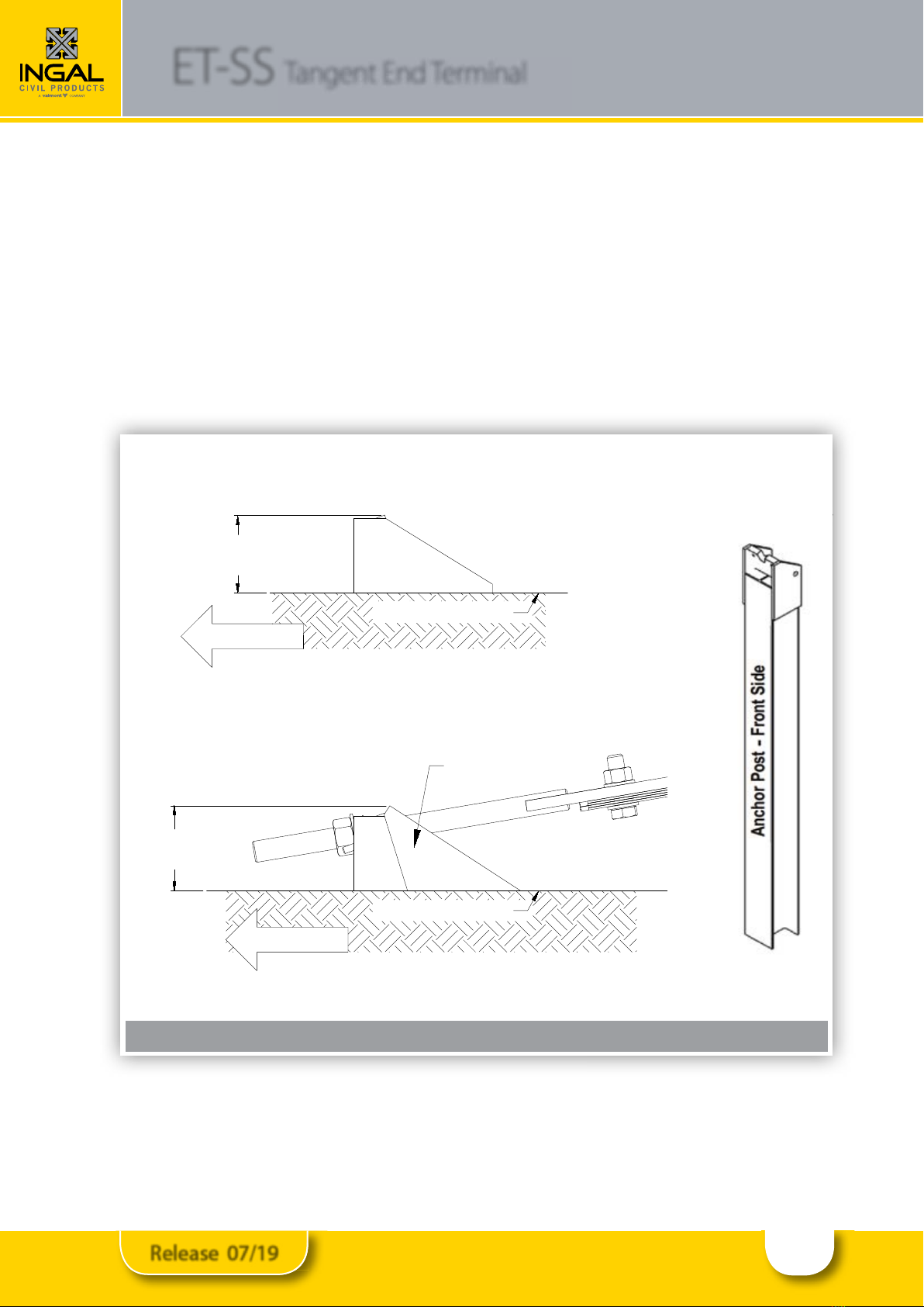
6.2 ET-SS System Anchor Post (Post 0) Placement
The ET-SS System Anchor Post (10007543) is the rst post of the ET-SS System and is designated as Post 0. The ET-
SSSystem Anchor Post is to be assembled plumb and oriented with the front side of post facing towards the upstream
end.
A. When assembled to the correct depth, the ET-SS System Anchor Post stub will protrude 89 mm above the nished
grade line (see Step 2 of this Assembly Manual).
B. When fully assembled, the ET-SS System Anchor Post (with Anchor Angles) will protrude 102 mm above the nished
grade line (see Step 12 of this Assembly Manual).
Caution: Ensure the ET-SS System Anchor Post is assembled in the orientation shown above. Failure to
follow this warning could result in serious injury or death in the event of a vehicle impact or collision
with the system.
Caution: Ensure the ET-SS System Anchor Post is assembled in the orientation shown above. Failure to
follow this warning could result in serious injury or death in the event of a vehicle impact or collision
with the system.
Figure 10: Anchor Post (Post 0) placement
F inished G rade Line
U pstream
mm201
)mm6-,0+(
Anchor Angle (2 EA)
mm98
)mm6-,0+(
U pstream
F inished G rade Line
A. Anchor Post Stub at Correct Height
B. Anchor Post (Fully Assembled) at Correct Height
15
Release 07/19
ET-SS Tangent End Terminal
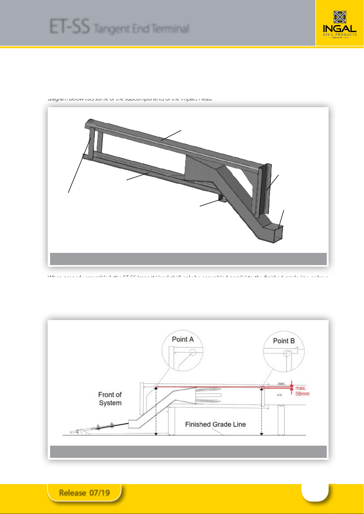
6.3 ET-SS System Impact Head
The ET-SS Impact Head (10007538) component is symmetrical and can be assembled on the left or right shoulder. The
diagram below lists some of the subcomponents of the Impact Head.
When properly assembled, the ET-SS Impact Head shall only be assembled parallel to the nished grade line or have
an upward tilt (towards front of the system). The elevation of the Impact Head can vary a maximum of 58 mm higher
at Point A relative to Point B. Point A is measured from the nished grade line to where the corner of the side plate
connects with the top guide channel and Point B is measured from the nished grade line to where the inside corner of
the vertical strap connects with the top guide channel.
diagram below lists some of the subcomponents of the Impact Head.
When properly assembled, the ET-SS Impact Head shall only be assembled parallel to the nished grade line or have
Figure 11: ET-SS System Impact Head
Created May 2016
All rights in copyright reserved
www.ingalcivil.co.nz
21
S of tS top
®
S ystem I mpactH ead
The SoftStop®Impact Head ( 15208A) component is symmetrical and can b e assemb led on the left or
right shou lder. The diagram b elow lists some of the su b components of the Impact Head.
T op G uide Channel
B ottom G uide Channel
V ertical S trap
S trik e P late
Connection B rack et
Chute
When properly assemb led, the SoftStop®Impact Head shall only b e assemb led parallel to the finished
grade line or hav e an u pw ard tilt ( tow ards front of the system) . The elev ation of the Impact Head can
v ary a max imu m of 58 mm higher at Point A relativ e to Point B. Point A is measu red from the finished
grade line to w here the corner of the side plate connects w ith the top gu ide channel and Point B is
measu red from the finished grade line to w here the inside corner of the v ertical strap connects w ith the
top gu idechannel.
www.ingalcivil.com.au
Figure 12: Correct assembly of the ET-SS Impact Head

16
Release 07/19
ET-SS Tangent End Terminal
7.0 TEST LEVEL 3 ASSEMBLY STEPS
Important: Always use safety precautions when performing assembly, maintenance, repair and/or
moving heaving equipment. Ensure proper personal protective equipment (PPE) is worn. Failure to
follow this warning could result in serious injury or death.
17
Release 07/19
ET-SS Tangent End Terminal
8.0 INSTALLATION PROCEDURE
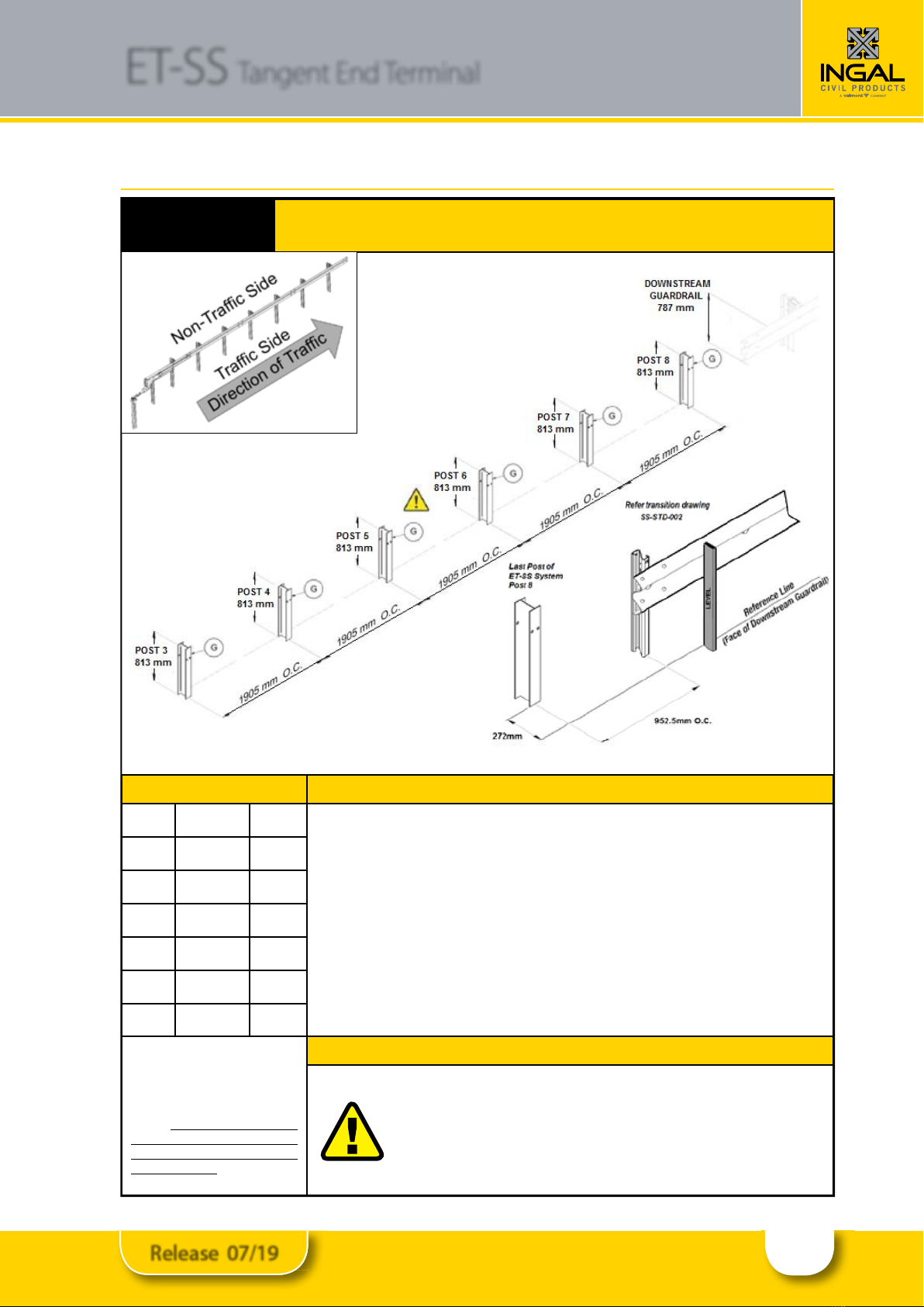
STEP 1 System Line Post Assembly (Posts 3-8)
PARTS INSTRUCTIONS
G 10007540 6 EA 1. Assemble all parts in the conguration & orientation as shown in the above
diagram.
2. The ET-SS System must be attached to a w-beam guardrail that has been
properly transitioned to 787 mm rail height per state/specifying agency (see
Appendix for transition drawing example).
3. Establish the location of the last post of the ET-SS System (Post 8) by placing a
level on the face of downstream guardrail to the nished grade and applying
oset and post spacing requirements shown above.
4. Ensure proper post spacing and post height is achieved for Posts 3-8 (Part G) per
shown dimensions above.
Use only Trinity Highway parts
that are specied herein for the
ET-SS System for assembling,
maintaining, or repairing the ET-SS
System. Do not utilise or otherwise
comingle parts from other systems
even if those systems are Trinity
Highway systems.
WARNINGS
Proper site grading must be accomplished in accordance
with local specifying agency guidelines. Failure to follow
this warning could result in serious injury or death in the
event of a vehicle impact or collision with the system.
18
Release 07/19
ET-SS Tangent End Terminal
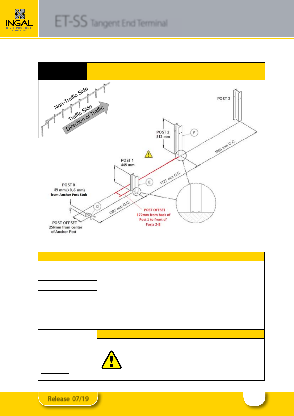
STEP 2 Post Assembly (Posts 0-2)
PARTS INSTRUCTIONS
F 10001402 1 EA 1. Assemble all parts in the conguration & orientation shown above.
2. Ensure proper oset for Post 0 (Part D) and Post 1 (Part E) is as shown on
dimension above and on the Post Displacement Diagram (page 30).
3. Ensure center of yielding holes for Post 1 & 2 are approximately at nished
grade, as shown.
4. Ensure Post 0 stub height does not exceed 89 mm above nished grade.
5. Ensure proper post spacing and post height is achieved per shown dimensions
above.
E 10007539 1 EA
D 10007543 1EA
Use only Trinity Highway parts
that are specied herein for the
ET-SS System for assembling,
maintaining, or repairing the ET-SS
System. Do not utilise or otherwise
comingle parts from other systems
even if those systems are Trinity
Highway systems.
WARNINGS
Proper site grading must be accomplished in accordance
with local road authority guidelines. Failure to follow this
warning could result in serious injury or death in the event
of a vehicle impact or collision with the system.

19
Release 07/19
ET-SS Tangent End Terminal
STEP 3 Oset Block Assembly (Posts 3-8)
PARTS INSTRUCTIONS
H 10001397 6 EA
1. Assemble all parts in the conguration & orientation shown above.
2. Attach (1 EA) Oset Block (Part H) on trac side of Posts 3-8. The Oset Block is
equipped with a self-hanging mounting tab.
Use only Trinity Highway parts
that are specied herein for the
ET-SS System for assembling,
maintaining, or repairing the ET-SS
System. Do not utilise or otherwise
comingle parts from other systems
even if those systems are Trinity
Highway systems.
WARNINGS
Do not use any Oset Block (Part H) if they show signs of
damage. Seek replacement from Ingal Civil Products prior
to assembly.
20
Release 07/19
ET-SS Tangent End Terminal
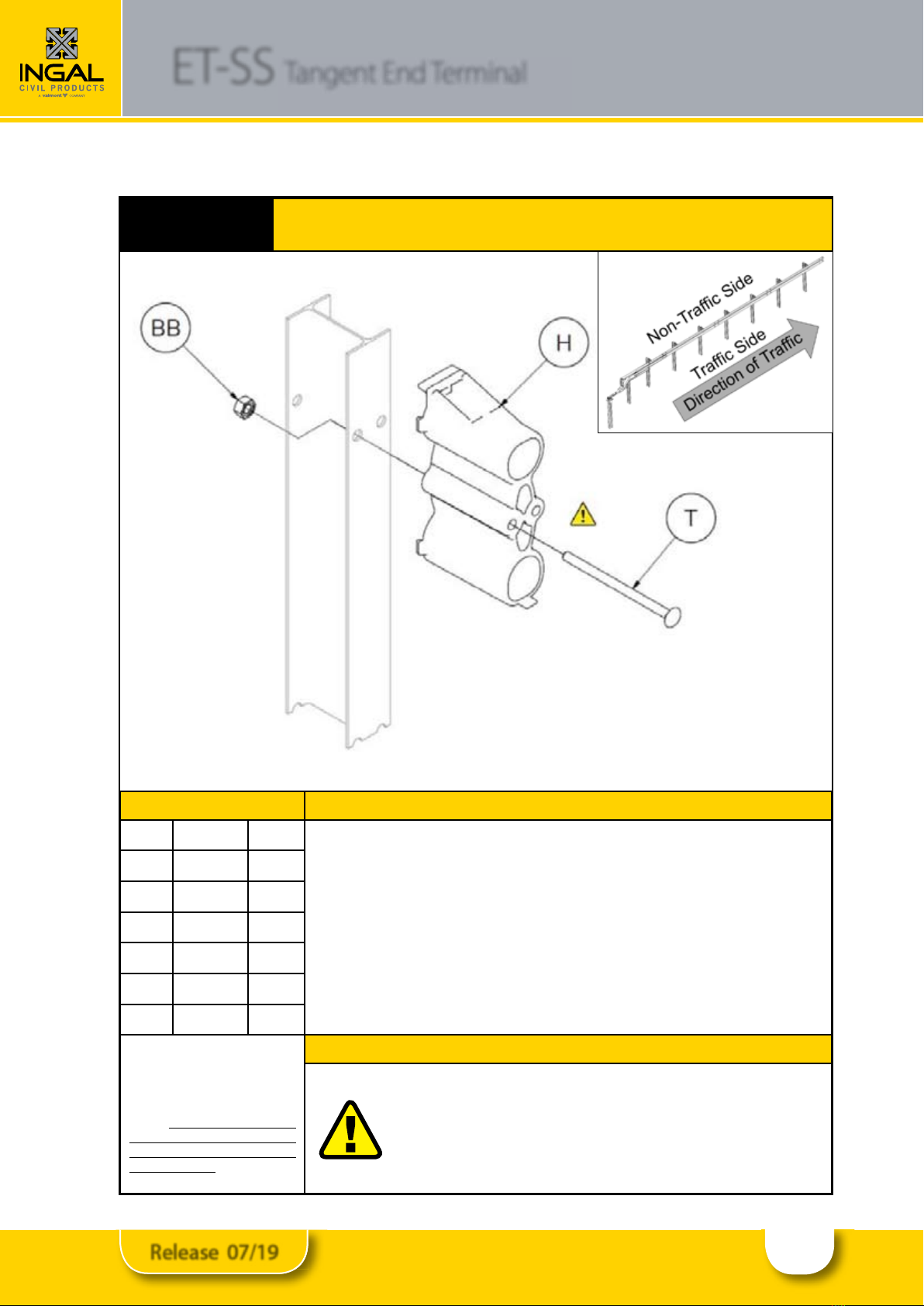
STEP 4 Oset Block Assembly (Post 2)
PARTS INSTRUCTIONS
H 10001397 1 EA
1. Assemble all parts in the conguration & orientation shown above.
2. Attach (1 EA) Oset Block (Part H) on trac side of Post 2. The Oset Block is
equipped with a self-hanging mounting tab.
3. Secure Oset Block to post with shown hardware.
4. Tighten all threaded hardware to a snug position with an appropriately sized
wrench or socket.
T 10001300 1 EA
BB 10001299 1EA
Use only Trinity Highway parts
that are specied herein for the
ET-SS System for assembling,
maintaining, or repairing the ET-SS
System. Do not utilise or otherwise
comingle parts from other systems
even if those systems are Trinity
Highway systems.
WARNINGS
Do not use any Oset Block (Part H) if they show signs of
damage. Seek replacement from Ingal Civil Products prior
to assembly.
Table of contents
Other INGAL Safety Equipment manuals


Popular Safety Equipment manuals by other brands

Lanex
Lanex PB-20 instruction manual

SKYLOTEC
SKYLOTEC ANCHOR ROPES Instructions for use

Besto
Besto Buoyancy Aid 50N Instructions for use

TEUFELBERGER
TEUFELBERGER NODUS Manufacturer's information and instructions for use

Troy Lee Designs
Troy Lee Designs Tbone Product owners manual

Innova
Innova Xtirpa Instruction and safety manual

bolle SAFETY
bolle SAFETY B810 quick start guide

SHENZHEN FANHAI SANJIANG ELECTRONICS
SHENZHEN FANHAI SANJIANG ELECTRONICS A9060T instruction manual

Hiltron security
Hiltron security POWER8E Installation and use manual

Salewa
Salewa MTN SPIKE user manual

Hatco
Hatco B-950P installation guide

Sitec
Sitec TX MATIC operating manual


