45528270_ed1 5
Pressing only on the inner race of the Bearing, mount the Rear
Spindle Bearing (8) onto the Spindle.
Apply lubricant to the gearing and position the Spindle within the
Gear Case (13), making sure the Planet Gears properly engage the
gear teeth of the Gear Case.
6. On the table of an arbor press and using a piece of tubing that
will clear the Spindle, Support the rear end of the Spindle and
press the Spindle Front Bearing (17) onto the Spindle.
7. Align one of the exterior slots on the Internal Gear (7) with the
two Internal Gear Keys (16) located opposite the Grease Fitting
(14) in the Gear Case (13). Push the Internal Gear into the Gear
Case until it stops against the gear teeth in the Case.
8.
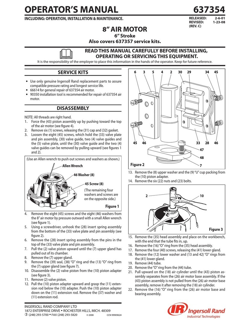
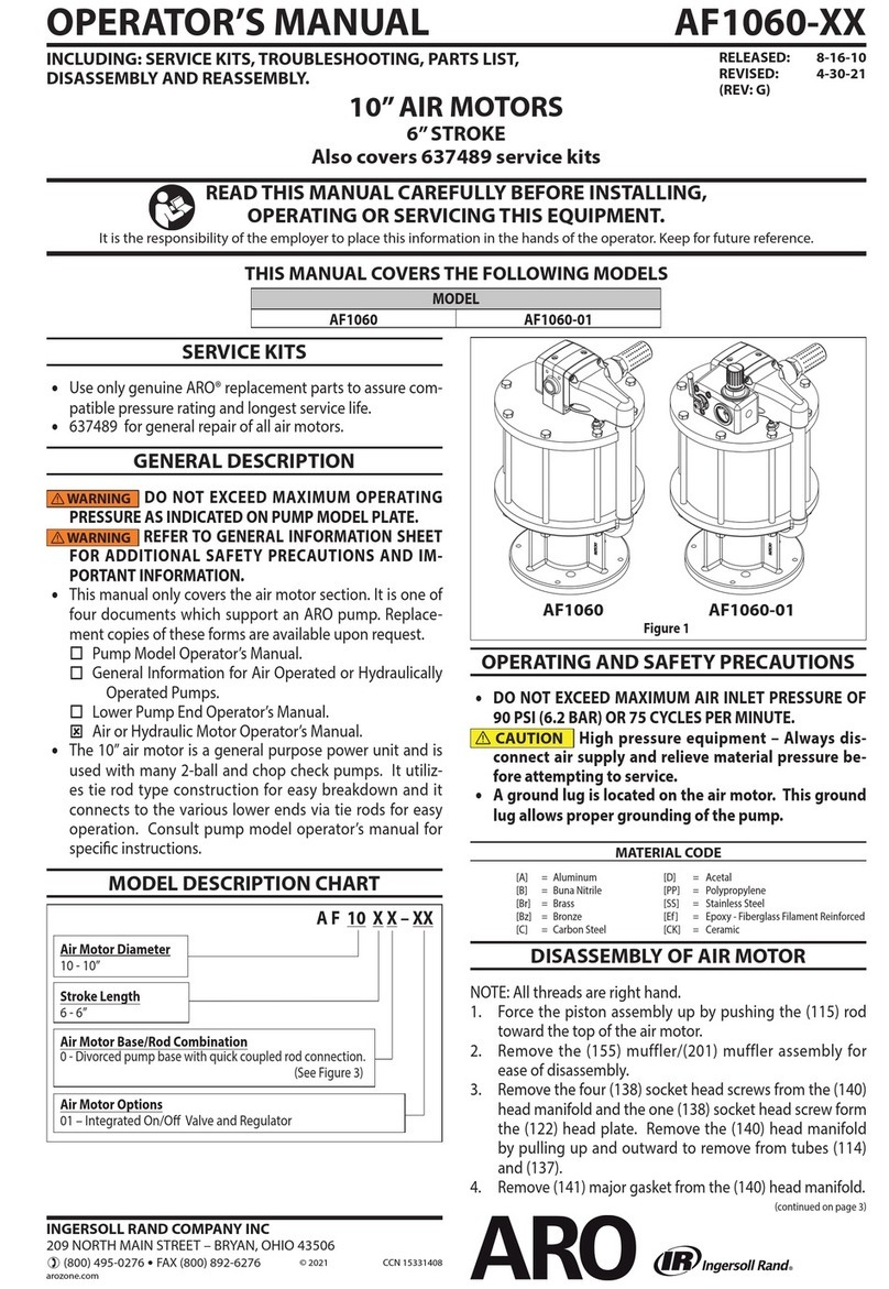
If the Gear Head Planet Gear Bearings (5) were removed from the
Gear Head Planet Gears (4), press new Bearings into the Gears
using a needle bearing inserting tool similar to the one shown in
Dwg. TPC488. If any Gears are damaged, install a complete new set
of Gears. Do not mix old Gears with new Gears in the same motor.
9. Support the web at the spline shaft end of the Gear Head (6) on
the table of an arbor press and position a Gear Head Planet Gear
with a Bearing in the web. The holes in the webs of the Gear Head
are tapered and smaller toward the spline shaft end of the Gear
Head. Press a Gear Head Planet Gear Shaft (2) through the rear
web and Bearing into the front web until the Shaft is ush with
the face of the rear web.
10. Repeat Step 9 with the remaining Gear Head Planet Gear and
Bearing.
11. Stand and support the assembled Gear Head on the table of an
arbor press with the spline shaft end downward and press the
Gear Head Bearing (1) onto the hub of the Gear Head.
12. Apply lubricant to the gear head gearing and while engaging
the spline of the Gear Head with the gearing of the Spindle and
Internal Gear, slide the assembled Gear Head into the Gear Case.
13. Mount the Oset Gear Case Adapter (18) to the Gear Case (13)
using the six Screws (20).
14. Slide the Oset Gear (21) onto the spline shaft and secure with
the Snap Ring (22).
15. Lubricate and install the O-ring (19).
Assembly of the Drive Module
Refer to Drawing 45504115 and associated parts list, for detailed
information regarding the part numbers and position within the
sub-assembly.
If removed during disassembly, place the Bearing Washer (4) in the
bearing recess, and using a needle bearing insertion tool similar
to the one shown in Dwg. TPC488, press a new Needle Bearing (6)
into the Oset Gear Case (3). Work some Ingersoll Rand No. 11
Bearing Grease between the rollers of the bearing.
Position the Drive Gear (8) on an arbor press, spline end up, and,
pressing only on the inner race of the bearing with a driver with
an inside diameter sucient to clear the gear shaft, press on the
Bearing (9), and install snap Ring (10). Apply about 227g (8 oz.)
of Ingersoll Rand No. 11 Bearing Grease to the assembled Drive
Gear, making certain to work the grease between all the gear
teeth, splines, and bearing surfaces.
Similarly, press the Bearing (19) onto the Drive Shaft (22), and
install Retaining Ring (13).
If removed for service, Press a new Seal (24), spring to the inside, and
Bearing (23) into the Drive Housing (25). Work some Ingersoll Rand
No. 11 Bearing Grease between the rollers of the bearing.
If removed for service, press a new Seal (11) into the Gear Case
Cover (14), seal spring to the inside. Install the Seal Retaining Ring
(12) into the Gear Case Cover.
Position the Oset Gear Case (3) at on a table with the Drive
Housing side, the side with the twelve hole pattern, facing
upward.
Wipe a thin lm of grease on the Drive Gear Thrust Washer (7), and
place the Washer on the lip of the bearing recess in the Gear Case,
and position the Drive Gear (8) properly.
Moisten the Gear Case Cover Seal (15) and Piston Seal (16) with
O-Ring lubricant and install them in their respective grooves on
the Gear Case Cover (14).
4.
5.
1.
2.
3.
4.
5.
6.
7.
8.
9.
Place the Gasket (5) on the Oset Gear case, and slide the
assembled Gear Case Cover (14), bearing recess rst and seal to
the outside, down over the Drive Gear until it contacts the Oset
Gear Case.
Position the Drive Shaft (22) along with the Bearing and Snap
Ring, into the Piston (18).
Insert the Spacer (20) and secure with the Snap Ring (21).
Place the O-ring (17) on the Piston and lubricate with an
appropriate O-ring lubricant. Apply a thin coat of Ingersoll Rand
No. 11 Bearing Grease to the outside surface of the Piston.
Mount the Piston (18) and Drive Shaft Assembly into the
Drive Gear (8).
Place the Drive Housing (25) over the Drive Shaft (22) and down until
it contacts the Gear Case Cover. Wipe a thin lm of Ingersoll Rand
No. 11 Bearing Grease on the bore of the Drive Housing.
Rotate to the proper alignment and secure with the eleven
Bolts (27) and Lock washers (26). Tighten to 11-12 ft-lbs.
Lubricate and install the O-ring (1) in the groove at the motor end
of the Oset Gear case.
Assembly of the Major Modules
Refer to drawing 45505153, and associated parts list, for more
details on Module assembly and the associated components.
Insert the Gearing Module (2) into the Drive Assembly (3). Rotate
the Output Shaft as necessary to allow the Gearing Module to
fully seat. Mount the Valve Mounting Bracket (8) onto the Gearing
Module. Secure with the four Screws (6) and Lockwashers (7).
Tighten to between 4-1/2 and 5 ft-lbs.
Insert the Motor/Brake Module (1) into the Gear Module (2).
Rotate the Output Shaft as necessary to allow the Motor/Brake
Module to fully seat. Secure with the three Screws (4) and
Lockwashers (5). Orient as necessary to align the holes and to
position the inlet air holes. Tighten to between 4-1/2 and 5 ft-lbs.
Mount the Flange (9) onto the Drive Housing. Rotate to properly
position, and to align the holes. Fasten with the six screws (10).
Tighten the Screws to between 12-14 ft-lbs.
Assembly of the Pinion and Associated Components
Refer to drawing 45535762, and associated parts list, for more
details on assembly and the associated components.
Place the Pinion (20) onto the Drive Shaft and secure with the
Pinion Bolt (21) and tighten to 180 - 220 ft-lbs.
Make sure the Pinion and the Drive Shaft are fully retracted into
the Drive Housing. Insert the Lock Pin Assembly (18) into the
forward most hole in the Drive Housing and tighten securely.
Reconnect the Piston Activation Air Tubes, (two places) (22).
Reconnect the Air Supply Tube (11).
Apply thread sealant (SMB-441) to threads of the Swivel Elbow
(two places) (12) and reconnect to the Barring Motor
Assembly (13). Tighten to hand tight plus 1 to 2 turns.
Attach remaining valving and hose if necessary.
Assembly of the Valve and Connector Kit
Refer to drawing 45535762, and associated parts list, for more
details on assembly and the associated components.
Thread Sealant (SMB-441) required on all NPT connections in the
assembly.
Tighten all NPT threads in the assembly to hand tight plus
1 to 2 turns.
Assemble three Elbows (14) to Valve (16). Place the Elbows in
Port 1, Port 2, and Port 4 of Valve and tighten to hand tight.
Assemble the Valve (16) to the Valve Mounting Bracket on the
Barring Motor Assembly using the Screws (15).
Tighten the Elbows (14) on the Valve (16) to the required
specications and orient as shown for routing of the Piston
Activation Tubes (11, 22).
Place the Elbow (17) into the‘”IN” Port of the Drive Housing and
orient approximately as shown to facilitate routing of the Piston
Activation Tube (22). Tighten to the specied requirements.
10.
11.
12.
13.
14.
15.
16.
17.
1.
2.
3.
4.
1.
2.
3.
4.
5.
6.
7.
1.
2.
3.
4.
5.
6.
7.


