General Instructions
1. Always press on the inner ring of a ball–type bearing when
installing the bearing on a shaft.
2. Always press on the outer ring of a ball–type bearing when
pressing the bearing into a bearing recess.
3. When grasping a tool or part in a vise, always use
leather–covered or copper–covered vise jaws to protect the
surface of the part and help prevent distortion. This is particularly
true of threaded members and housings.
4. Except for bearings and mechanism parts, always clean every part
and wipe every part with a thin lm of oil before installation.
5. Wipe a thin lm of mechanism uid on all internal mechanism
components before installing them in the mechanism.
6. Apply a lm of o–ring lubricant to every o–ring before
installation.
Assembly of the Motor
1. If the Reverse Valve Bushing Seal (10) was removed from the
reverse valve bushing, install a new Seal inside the bushing.
2. Install a new Reverse Valve Seal (9) on the Reverse Valve (8).
3. Being careful not the cut or nick the Seals, insert the Reverse
Valve, large hub trailing, into the Motor Housing (1) from the lever
side of the Housing. Make certain the hole for the Reverse Lever
Retaining Pin (4) and the valve porting are properly aligned.
4. Position the Throttle Lever (11) on the Housing and secure it by
pressing the Lever Retaining Pin (12) through the Housing and
Lever.
5. Install the Throttle Rod Seal (6) in the groove on the large hub of
the Throttle Rod (5).
6. Install the Reverse Lever Seal (3) on the hub of the
Reverse Lever (2).
7. Insert the Throttle Rod Assembly, small end leading, into the
Reverse Valve Assembly followed by the Throttle Rod Spring (7)
and assembled Reverse Lever.
8. Align the hole in the Reverse Lever with the hole in the Reverse
Valve and install the Reverse Lever Retaining Pin in the aligned
holes.
9. Place the Exhaust Deector Seal (14) on the inlet and of the
Motor Housing followed by the Exhaust Deector.
10. Thread the Inlet Bushing (15) into the small hub the Housing and,
after rotating the Deector to the desired position, tighten the
Inlet Bushing between 30 and 35 ft–lb (40 and 47 Nm) torque.
11. Using an arbor press and a piece of tubing that contacts the outer
ring of the bearings, press the Front End Plate Bearing (27) into
the Front End Plate (25) and the Rear End Plate Bearing (19) into
the Rear End Plate (18).
(Refer to Dwg. TPD1274).
(Dwg. TPD1274)
12. Stand the Rotor (25) on the table of an arbor press. It should be
upright on a at metal plate having a clearance hole for the shaft.
The shaft with the hex must be downward.
13. Place a 0.001”(0.025 mm) shim on the upward surface of the large
portion of the rotor body. Using a piece of tubing that contacts
the inner ring of the bearing, press the Rear Rotor Bearing and
Rear End Plate, End Plate leading, onto the shaft of the Rotor until
the End Plate contacts the shim. Remove the shim.
14. Coat each Vane (24) with a thin lm of oil and insert a Vane into
each of the rotor vane slots with the straight edge of the Vane
outward.
15. Install the Cylinder (20) over the Vanes and Rotor with the end of
the Cylinder having the two holes in straight alignment nearest
the end face positioned away from the Rear End Plate. Make
certain the End Plate Dowel (24) enters the hole in the face of the
Rear End Plate and not the porting slot.
16. Place the Front End Plate and Bearing against the face of the
Cylinder, Bearing end trailing. Make certain the End Plate Dowel
in that end of the cylinder enters the hole in the End Plate and
not the porting slot.
17. Place the Rear End Plate Spacer (17) against the Rear End Plate
making certain that the Rear End Plate Dowel enters the hole in
the Spacer and the external slots align.
4. Remove the motor from the vise jaws and remove the Front End
Plate (25), Front Rotor Bearing (27), Cylinder Assembly (20) and
Vanes (24) from the Rotor.
5. Remove the Rear End Plate Spacer (17) from the Motor Housing
or the Rear End Plate (18).
6. On the table of an arbor press, support the Rear End Plate with
blocks as close to the Rotor as possible and press the Rotor out of
the Rear End Plate and Rear Rotor Bearing (19).
In the following step, do not enlarge or damage the
shaft hole in the End Plate when removing the
Bearing.
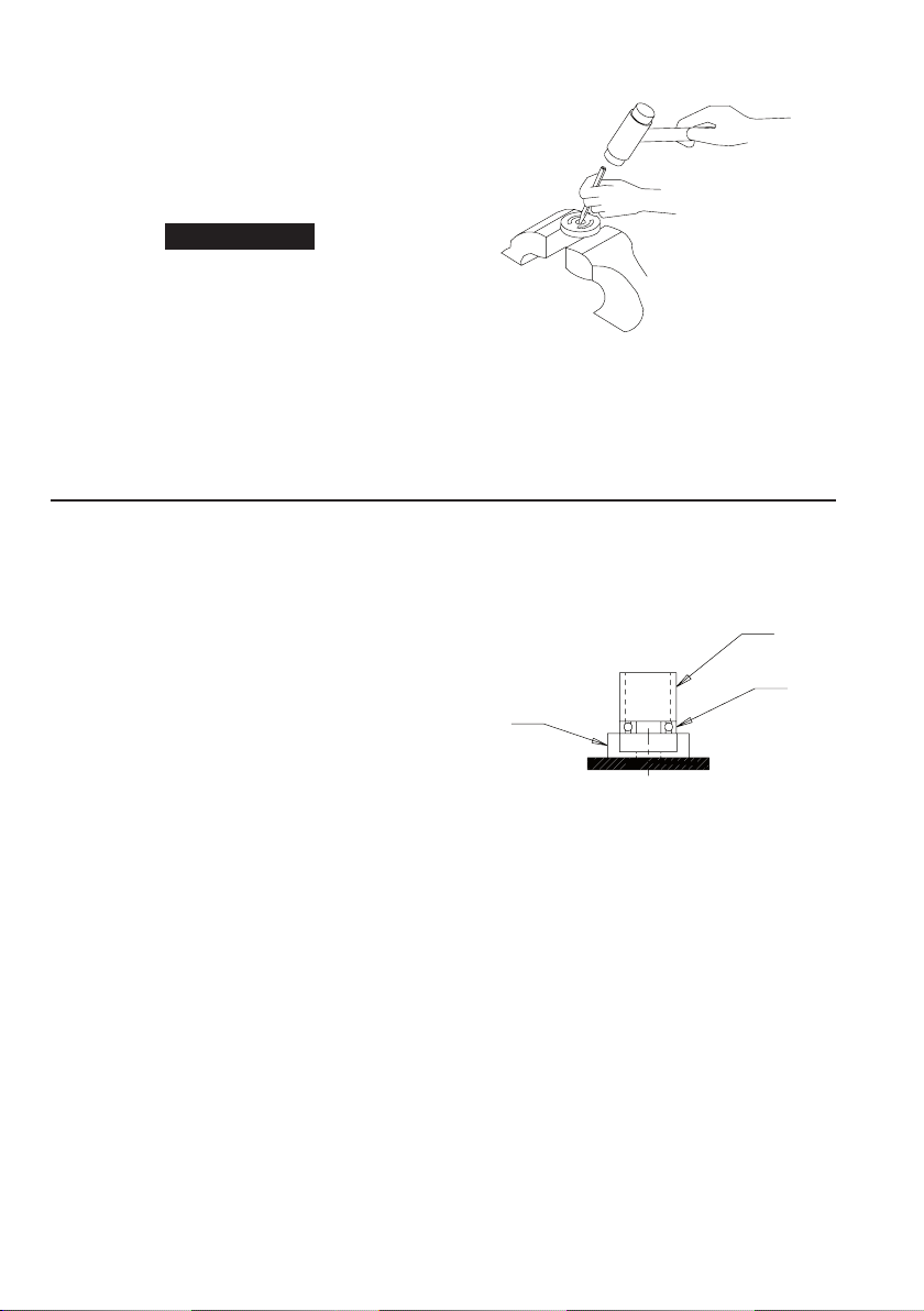
7. To remove the Rear Rotor Bearing from the Rear End Plate, use a
small drift or pin punch through the central opening of the Rear
End Plate to tap the Bearing out of the End Plate.
(Refer to Dwg. TPD1271)
8. Using an adjustable wrench, unscrew and remove the Inlet
Bushing (15). Remove the Exhaust Deector (13) and Exhaust
Deector Seal (14).
9. Using a pin punch and without damaging the Reverse Lever (2),
remove the Reverse Lever Retaining Pin (4) and separate the
Lever from the Reverse Valve Assembly (8). Remove the Reverse
Valve Seal (9) from the Lever.
(Dwg. TPD1271)
10. Remove the Throttle Rod Assembly (5) and Throttle Rod Spring (7)
from the Reverse Valve Assembly (8).
11. Using a pin punch, tap the Lever Retaining Pin (12) out of the
Throttle Lever (11) and Housing and remove the Lever.
12. Push the Reverse Valve Assembly out the lever side of the
Housing.
Assembly