EN
03528742_ed15 EN-1
Product Safety Information
Intended Use:
These Riveting Hammers are designed for light weight riveting applications.
For additional information refer to Product Safety Information Manual Form 04581450.
Manuals can be downloaded from ingersollrandproducts.com.
Product Specications
Model Handle Power
Regulator
Blows per
min.
Piston Stroke Sound Level dB (A)
(ISO15744)
Vibration (m/s2)
(ISO28927)
Inch (mm) † Pressure (Lp)‡ Power
(Lw)Level *K
AVC10C1 button throttle --- 3,200 1-7/8 (47) 92.0 103.0 13.3 1.9
AVC10C1-EU button throttle --- 3,200 1-7/8 (47) 92.0 103.0 13.3 1.9
AVC10A1 oset built-in 3,200 1-7/8 (47) 92.0 103.0 13.3 1.9
AVC10A1-EU oset built-in 3,200 1-7/8 (47) 92.0 103.0 13.3 1.9
AVC12A1 oset built-in 2,100 3 (76) 91.1 102.1 8.0 1.8
AVC12A1-EU oset built-in 2,100 3 (76) 91.1 102.1 8.0 1.8
AVC13A1 oset built-in 1,725 4 (101) 94.2 105.2 8.0 1.8
AVC13A1-EU oset built-in 1,725 4 (101) 94.2 105.2 8.0 1.8
AVC26A1 oset built-in 1,120 6 (152) 92.6 103.6 8.0 1.8
AVC26A1-EU oset built-in 1,120 6 (152) 92.6 103.6 8.0 1.8
AVC26B1 pistol grip built-in 1,120 6 (152) 92.6 103.6 8.0 1.8
AVC26B1-EU pistol grip built-in 1,120 6 (152) 92.6 103.6 8.0 1.8
† KpA = 3dB measurement uncertainty * K = Vibration measurement uncertainty
‡ KwA = 3dB measurement uncertainty
Sound and vibration values were measured in compliance with internationally recognized test standards.The exposure to the user in
a specic tool application may vary from these results. Therefore, on site measurements should be used to determine the hazard level
in that specic application.
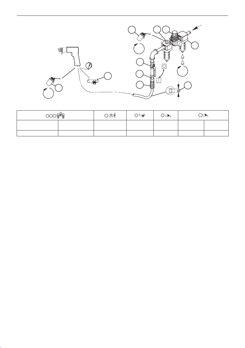
Installation and Lubrication
Size air supply line to ensure tool’s maximum operating pressure (PMAX) at tool inlet. Drain condensate from valve(s) at low point(s) of piping,
air lter and compressor tank daily. Install a properly sized Safety Air Fuse upstream of hose and use an anti-whip device across any hose
coupling without internal shut-o, to prevent hose whipping if a hose fails or coupling disconnects. See drawing 16576175 and table on
page 2. Maintenance frequency is shown in a circular arrow and dened as h=hours, d=days, and m=months of actual use. Items identied as:
1. Air lter 6. Thread size
2. Regulator 7. Coupling
3. Lubricator 8. Safety Air Fuse
4. Emergency shut-o valve 9. Oil
5. Hose diameter 10. Oil - before starting, into air inlet
Note: Before storing the tool or leaving idle exceeding 24 hours:
- Pour 3 cm3of Ingersoll Rand # 10 oil into air inlet and run tool for 5 seconds.
Adjustments
Always turn o the air supply, bleed the air pressure and disconnect the air supply hose when not in use, before installing, removing or
adjusting any accessory on this tool, or before performing any maintenance on this tool or any accessory.
Keep the Handle tight on the Barrel.
After the rst 24 hours of operation, remove the Exhaust Deector and Locking Key. Clamp the Barrel ats in a leather-covered or copper-
covered vise and using a wrench at least 12”(305 mm) long, draw the handle as tightly as possible. For aluminium handles, tighten to 160 ft-lb
(216 Nm) torque. For all other Handles, tighten to 180 ft-lb (244 Nm) torque.
Do not attempt to pry apart the two sections of the Valve Box. Grasp the front section in the hand and insert a rod that will pass through the
Valve and contact the rear section. Lightly strike the rod until the two sections are separated.
Keep the front and rear sections of a Valve Box as a unit. They are factory matched and must not be mismatched.